CN113890035A - A multi-mode unified control method based on series-parallel power router - Google Patents
A multi-mode unified control method based on series-parallel power router Download PDFInfo
- Publication number
- CN113890035A CN113890035A CN202111140974.6A CN202111140974A CN113890035A CN 113890035 A CN113890035 A CN 113890035A CN 202111140974 A CN202111140974 A CN 202111140974A CN 113890035 A CN113890035 A CN 113890035A
- Authority
- CN
- China
- Prior art keywords
- mode
- current
- grid
- control
- series
- Prior art date
- Legal status (The legal status is an assumption and is not a legal conclusion. Google has not performed a legal analysis and makes no representation as to the accuracy of the status listed.)
- Granted
Links
- 238000000034 method Methods 0.000 title claims abstract description 47
- 238000006243 chemical reaction Methods 0.000 claims abstract description 11
- 230000007246 mechanism Effects 0.000 claims abstract description 10
- 230000008569 process Effects 0.000 claims description 18
- 238000004146 energy storage Methods 0.000 claims description 8
- 230000009466 transformation Effects 0.000 claims description 8
- 238000010248 power generation Methods 0.000 claims description 4
- 230000000903 blocking effect Effects 0.000 claims description 3
- 230000006872 improvement Effects 0.000 abstract description 3
- 238000010586 diagram Methods 0.000 description 11
- 238000011217 control strategy Methods 0.000 description 6
- 230000001939 inductive effect Effects 0.000 description 2
- 230000008802 morphological function Effects 0.000 description 2
- 230000008901 benefit Effects 0.000 description 1
- 230000005540 biological transmission Effects 0.000 description 1
- 239000003990 capacitor Substances 0.000 description 1
- 230000008878 coupling Effects 0.000 description 1
- 238000010168 coupling process Methods 0.000 description 1
- 238000005859 coupling reaction Methods 0.000 description 1
- 238000005516 engineering process Methods 0.000 description 1
- 230000010354 integration Effects 0.000 description 1
- 230000003993 interaction Effects 0.000 description 1
- 230000007935 neutral effect Effects 0.000 description 1
- 230000035699 permeability Effects 0.000 description 1
- 230000000087 stabilizing effect Effects 0.000 description 1
Images


Classifications
-
- H—ELECTRICITY
- H02—GENERATION; CONVERSION OR DISTRIBUTION OF ELECTRIC POWER
- H02J—CIRCUIT ARRANGEMENTS OR SYSTEMS FOR SUPPLYING OR DISTRIBUTING ELECTRIC POWER; SYSTEMS FOR STORING ELECTRIC ENERGY
- H02J3/00—Circuit arrangements for AC mains or AC distribution networks
- H02J3/02—Circuit arrangements for AC mains or AC distribution networks using a single network for simultaneous distribution of power at different frequencies; using a single network for simultaneous distribution of AC power and of DC power
-
- H—ELECTRICITY
- H02—GENERATION; CONVERSION OR DISTRIBUTION OF ELECTRIC POWER
- H02J—CIRCUIT ARRANGEMENTS OR SYSTEMS FOR SUPPLYING OR DISTRIBUTING ELECTRIC POWER; SYSTEMS FOR STORING ELECTRIC ENERGY
- H02J3/00—Circuit arrangements for AC mains or AC distribution networks
- H02J3/28—Arrangements for balancing of the load in a network by storage of energy
-
- H—ELECTRICITY
- H02—GENERATION; CONVERSION OR DISTRIBUTION OF ELECTRIC POWER
- H02J—CIRCUIT ARRANGEMENTS OR SYSTEMS FOR SUPPLYING OR DISTRIBUTING ELECTRIC POWER; SYSTEMS FOR STORING ELECTRIC ENERGY
- H02J3/00—Circuit arrangements for AC mains or AC distribution networks
- H02J3/38—Arrangements for parallely feeding a single network by two or more generators, converters or transformers
- H02J3/388—Islanding, i.e. disconnection of local power supply from the network
-
- H—ELECTRICITY
- H02—GENERATION; CONVERSION OR DISTRIBUTION OF ELECTRIC POWER
- H02J—CIRCUIT ARRANGEMENTS OR SYSTEMS FOR SUPPLYING OR DISTRIBUTING ELECTRIC POWER; SYSTEMS FOR STORING ELECTRIC ENERGY
- H02J2203/00—Indexing scheme relating to details of circuit arrangements for AC mains or AC distribution networks
- H02J2203/20—Simulating, e g planning, reliability check, modelling or computer assisted design [CAD]
Landscapes
- Engineering & Computer Science (AREA)
- Power Engineering (AREA)
- Inverter Devices (AREA)
Abstract
The invention discloses a multi-mode unified control method based on a series-parallel electric energy router, which relates to the technical field of power electronic equipment, and comprises the following steps: the method comprises the steps of phase-locked loop, dq0 conversion, grid-connected fusing mechanism, multi-mode operation control, direct-current bus voltage equalizing control, alternating-current power grid current reference generation, alternating-current power grid current control and SPWM modulation. The multi-mode operation control and grid-connected fusing mechanism is an important improvement of the invention, namely the electric energy router can operate in a power grid mode, a cooperative mode, an island mode and a grid-connected mode by uniformly controlling a grid-connected operation coefficient and a multi-mode operation coefficient, and seamless switching among the four modes is realized; by controlling the fusing coefficient, the influence of the voltage drop of the direct-current bus on the stability of the electric energy router in the grid-connected mode can be overcome.
Description
Technical Field
The invention relates to the technical field of power electronic equipment, in particular to a multi-mode unified control method based on a series-parallel electric energy router.
Background
With the continuous aggravation of new energy permeability and the large-scale access of an energy storage device and an alternating current/direct current load, the power grid structure, morphological function and load composition of a power system are changing deeply, and the characteristics of 'grid-source-storage-load' multi-element coupling and complex structure presented by the power grid structure, morphological function and load composition provide new requirements for stable operation, different forms of energy conversion and distribution, power quality problems and the like of the power system. In view of the above features, an Electric Energy Router (EER), as a power electronic device having various forms of electrical interfaces and Energy conversion functions, can implement effective integration of new Energy, an Energy storage device and an Electric power system, efficient conversion between various forms of Energy, and high-quality power supply to ac/dc loads.
The EER for the low-voltage distribution network generally adopts a two-stage conversion scheme, namely an AC/DC + DC/AC converter, and can be specifically divided into a series-type EER and a series-parallel-type EER according to the connection form of the two-stage converter. Compared with the series-parallel EER, the series-parallel EER can simultaneously realize flexible operation of active power and reactive power, and the two-channel energy supply mode of the series-parallel EER can enable the EER to convert and transmit energy under the condition that the rated capacity of the system is larger than that of the system, so the series-parallel EER has the advantage of high-power energy transmission, such as the invention patent CN 202011322000. Under the interaction of various energy sources, the series-parallel EER has various operation modes, which are specifically divided into a power grid mode: the AC power grid provides all energy for the load; a cooperation mode: the alternating current power grid and the new energy or/and the energy storage device cooperate to provide energy for the load; island mode: the new energy or/and the energy storage device provide all energy for the load; grid connection mode: on the premise of preferentially ensuring the load power consumption, the new energy or/and the surplus energy in the energy storage device are fed to the power grid.
However, how to implement unified control over multiple modes and complete seamless switching between different modes for multiple operation modes of the low-voltage distribution network EER is a technical difficulty which is not related to the existing control technology of the low-voltage distribution network EER at present. Further, due to different topology forms, the control method in the prior art is not suitable for performing multi-mode control on the series-parallel EER, for example, patent nos. CN201910348552 and CN202011332313 are control methods for medium-voltage distribution networks and are directed at three-level or multi-level conversion schemes.
Disclosure of Invention
The technical problem to be solved by the invention is to provide a multi-mode unified control method based on a series-parallel electric energy router, so that the electric energy router can operate in a power grid mode, a cooperative mode, an island mode and a grid-connected mode, and seamless switching among the four modes is realized; by controlling the fusing coefficient, the influence of the voltage drop of the direct-current bus on the stability of the electric energy router in the grid-connected mode is overcome.
In order to solve the technical problems, the technical scheme adopted by the invention is as follows:
a multi-mode unified control method based on a series-parallel electric energy router comprises the following steps: the method comprises the following steps of phase-locked loop, dq0 conversion, a grid-connected fusing mechanism, multi-mode operation control, direct-current bus voltage equalizing control, alternating-current power grid current reference generation, alternating-current power grid current control and SPWM modulation; the series-parallel type electric energy router comprises a series converter, a parallel converter, a transformer, an alternating current bus, a direct current bus, an alternating current power grid interface, an energy storage device interface, a new energy power generation interface, a plurality of alternating current load interfaces and a plurality of direct current load interfaces.
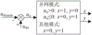
The technical scheme of the invention is further improved as follows: the control process of the grid-connected fusing mechanism comprises the following steps: measured value u of total voltage of direct current busdcAnd the minimum direct current bus total voltage set value udcminObtaining a difference value u after comparisoneUsing said difference ueJudging values of fusing coefficients x and y; wherein, fusing coefficients x, y and u are in a grid-connected modeeThe relationship of (1) is:

when u ise>When 0, then udc>udcminThe direct current bus has the capability of operating in a grid-connected mode, and the two fusing coefficients are x ═ 1 and y ═ 0 respectively; when u iseWhen u is less than or equal to 0, u isdc≤udcminThe direct-current bus cannot support a grid-connected mode, and the two fusing coefficients are x ═ 0 and y ═ 1 respectively, so that the electric energy router exits the grid-connected mode;
in other three modes, the two fusing coefficients are set to be x ═ 0 and y ═ 1 respectively, so that the grid-connected mode is in a blocking state.
The technical scheme of the invention is further improved as follows: the control process of the multi-mode operation control comprises the following steps: ac mains voltage uSdAc bus voltage uLdAnd AC bus current iLdAfter passing through a low-pass filter, extracting corresponding fundamental positive sequence components And
And then combining with rated current i of the parallel converterparRObtaining a multi-mode operation control output current iSdmComprises the following steps:

wherein k isgDetermining a second condition for the electric energy router to operate in a grid-connected mode for grid-connected operation coefficients; k is a radical ofmIs a multi-mode operating factor;
by controlling kmAnd kgThe method comprises the following steps that the electric energy router operates in a power grid mode, a coordination mode, an island mode and a grid-connected mode, seamless switching among the four modes is realized, and the method comprises the following steps: (1) and (3) power grid mode: k is a radical ofm=1,k g0, x is 0; (2) collaborationMode (2): 0<km<1,k g0, x is 0; (3) island mode: k is a radical ofm=0, k g0 or 1, x is 0; (4) grid connection mode: 0<km<1,kg=1,x=1。
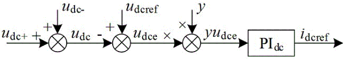
The technical scheme of the invention is further improved as follows: the control process of the direct current bus voltage control comprises the following steps: calculating a DC bus voltage reference value udcrefAnd the measured value u of the DC bus voltagedcDifference u ofdce=udcref-udcThen multiplied by the fusing coefficient y to obtain a magnitude yudceVia PI controller PIdcAfter adjustment, the direct current bus voltage control output current i is obtaineddcref(ii) a When the electric energy router operates in a grid-connected mode, setting y to be 0 so as to further control idcrefIf the voltage is 0, cutting off the voltage control of the direct current bus; and when the system operates in other three modes, if y is set to be 1, the direct current bus voltage control is added.
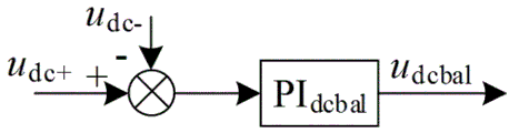
The technical scheme of the invention is further improved as follows: the control process of the voltage-sharing control of the direct-current bus comprises the following steps: the difference value between the measured values of the positive and negative DC bus voltages is processed by PI controller PIdcbalAfter adjustment u is obtaineddcbal。
The technical scheme of the invention is further improved as follows: the control process of the current reference generation of the alternating current power grid comprises the following steps: the multi-mode operation controls the output current iSdmControlling output current i with the DC bus voltagedcrefAdding to obtain AC network current reference iSdref。
The technical scheme of the invention is further improved as follows: the control process of the alternating current network current control comprises the following steps: the AC mains current reference iSdrefMultiplying the obtained value by the transformation ratio n of the transformer to obtain a d-axis current reference q-axis and 0-axis current references
 And
And are all set to zero; calculating the current reference
 And
And respectively connected with the measured output current value i of the series converterserd、iserqAnd iser0Is passed through a PI controller PIserThen, the current dq decoupling output and the voltage at two ends of the transformer are superposed to form a modulation signal u under a dq0 coordinate systemserd、userqAnd user0(ii) a The modulation signal userd、userqAnd user0Carrying out inverse transformation on dq0 and then carrying out voltage-sharing control on the output u and the DC bus voltagedcbalSuperposing to obtain a modulation signal under an abc coordinate system
 And
And
the technical scheme of the invention is further improved as follows: the phase-locked loop includes: converting the three-intersection flow in the abc coordinate system into a direct current flow in a dq0 coordinate system through dq0 conversion; and generating a driving signal of a switching tube in the series converter by modulating a modulation signal in an abc coordinate system through the SPWM.
Due to the adoption of the technical scheme, the invention has the technical progress that:
the invention realizes the unified control of a power grid mode, a cooperative mode, an island mode and a grid-connected mode, completes the seamless switching among different modes and meets various operation modes of series-parallel EERs.
The invention realizes peak clipping and valley filling of an alternating current power grid, timely consumption of new energy, uninterrupted power supply of alternating current and direct current loads, new energy grid-connected power generation, stable operation of the power grid during power failure or fault, and meets various application scenes of series-parallel EER.
The grid-connected fusing mechanism is convenient for overcoming the influence of voltage drop of a direct current bus on the stability of the electric energy router in a grid-connected mode; the multi-mode operation control facilitates controlling the power router to operate in multiple modes; the direct current bus voltage control is used for stabilizing the direct current bus voltage within a certain expected value; the direct current bus voltage equalizing control is used for controlling the voltage balance of the positive direct current bus and the negative direct current bus; the AC grid current reference generation is used for generating an AC grid current reference; the alternating current network current control is used for controlling the amplitude, frequency and phase of the alternating current network current; the phase-locked loop is used for tracking the frequency of the alternating current power grid voltage.
Drawings
Fig. 1 is a schematic diagram of a series-parallel type EER topology structure facing a low-voltage distribution network;
FIG. 2 is a multi-mode unified control overall design diagram based on series-parallel EER of the present invention;
FIG. 3 is a schematic diagram of a grid-connected fusing mechanism of the present invention;
FIG. 4 is a schematic diagram of the multi-mode operation control of the present invention;
FIG. 5 is a schematic diagram of the DC bus voltage control of the present invention;
FIG. 6 is a schematic diagram of voltage-sharing control of the DC bus according to the present invention;
FIG. 7 is a schematic diagram of the AC mains current reference generation of the present invention;
FIG. 8 is a schematic diagram of AC mains current control according to the present invention;
FIG. 9 is a schematic diagram of a series converter control strategy according to the present invention;
fig. 10 is a schematic diagram of a parallel converter control strategy according to the present invention.
Detailed Description
The present invention will be described in further detail with reference to the following examples:
the invention discloses a multi-mode unified control method based on a series-parallel electric energy router, wherein the multi-mode unified control provided by the invention is designed based on series-parallel EER, and the EER topological structure is shown in figure 1 and comprises a series converter, a parallel converter, a transformer, an alternating current bus, a direct current bus, an alternating current power grid interface, an energy storage device interface, a new energy power generation interface, an alternating current load interface and a direct current load interface. The series converters and the parallel converters are three-phase half-bridge power electronic converters and are connected in a back-to-back mode, the series converters are connected at the AC power grid interface in series through the transformer, and the parallel converters are connected at the AC bus in parallel.
Specifically, S1~S6The series converter switching tube; l issera,b,cThe three-phase filter inductor is the three-phase filter inductor of the series converter; u. of1a,b,cThe three-phase bridge arm voltage of the series converter is obtained; i.e. isera,b,cOutputting current for three phases of the series converter; s7~S12The parallel converter switching tube; l ispara,b,cAnd Cpara,b,cThe three-phase filter is the parallel converter; u. of2a,b,cThe three-phase bridge arm voltage of the parallel converter is obtained; i.e. i2a,b,cThree-phase inductive current of the parallel converter; i.e. ipara,b,cOutputting current for three phases of the parallel converter; u. ofSa,b,cThree-phase voltage of an alternating current power grid; i.e. iSa,b,cThree-phase current of an alternating current power grid; n is a neutral line; u. ofCa,b,cPrimary side three-phase voltage of the transformer; u. ofLa,b,cThe three-phase voltage of the alternating current bus is obtained; i.e. iLa,b,cThree-phase current of the alternating current bus is obtained; cdc+And Cdc-Positive and negative capacitors of the direct current bus; u. ofdc+And udc-And the voltage is positive and negative voltage of the direct current bus.
As shown in fig. 2, a multi-mode unified control method based on a series-parallel type electric energy router includes: the method comprises the steps of phase-locked loop, dq0 conversion, grid-connected fusing mechanism, multi-mode operation control, direct-current bus voltage equalizing control, alternating-current power grid current reference generation, alternating-current power grid current control and SPWM modulation.
As shown in fig. 3, the grid-connected fusing mechanism is a first important improvement of the present invention, and is used to overcome the stability influence of the dc bus voltage drop on the electric energy router in the grid-connected mode, and the control process is as follows: DC bus assemblyMeasured value u of bulk voltagedcAnd the minimum direct current bus total voltage set value udcminObtaining a difference value u after comparisoneUsing said difference ueAnd judging the values of the fusing coefficients x and y. Specifically, fusing coefficients x, y and u are set in a grid-connected modeeThe relationship of (1) is:

the above relationship can be expressed as: when u ise>When 0, then udc>udcminThe direct current bus has the capability of operating in a grid-connected mode, and the two fusing coefficients are x ═ 1 and y ═ 0 respectively, which is also the first condition for determining that the electric energy router operates in the grid-connected mode; when u iseWhen u is less than or equal to 0, u isdc≤udcminThe direct-current bus cannot support a grid-connected mode, and the two fusing coefficients are x ═ 0 and y ═ 1 respectively, so that the electric energy router exits the grid-connected mode.
In other three modes, the two fusing coefficients are set to x ═ 0 and y ═ 1 respectively, so that the grid-connected mode can be in a blocking state.
As shown in fig. 4, the multi-mode operation control is a second important improvement of the present invention, and is used for controlling the power router to operate in multiple modes, and the control process is as follows: ac mains voltage uSdAc bus voltage uLdAnd AC bus current iLdAfter passing through a low-pass filter, extracting corresponding fundamental positive sequence components
 And
And then combining with rated current i of the parallel converterparRCan obtain multi-mode operation control output current iSdmComprises the following steps:

wherein k isgDetermining a second condition for the electric energy router to operate in a grid-connected mode for grid-connected operation coefficients; k is a radical ofmIs a multi-mode coefficient of operation.
By controlling kmAnd kgThe electric energy router can operate in a power grid mode, a coordination mode, an island mode and a grid-connected mode, and seamless switching among the four modes is realized, and the specific expression is as follows: (1) and (3) power grid mode: k is a radical ofm=1,k g0, x is 0; (2) a cooperation mode: 0<km<1,k g0, x is 0; (3) island mode: k is a radical ofm=0, k g0 or 1, x is 0; (4) grid connection mode: 0<km<1,kg=1,x=1。
As shown in fig. 5, the dc bus voltage control is used to stabilize the dc bus voltage at a certain desired value, and the control process includes: calculating a DC bus voltage reference value udcrefAnd the measured value u of the DC bus voltagedcDifference u ofdce=udcref-udcThen multiplied by the fusing coefficient y to obtain a magnitude yudceVia PI controller PIdcAfter adjustment, the direct current bus voltage control output current i is obtaineddcref. When the electric energy router operates in a grid-connected mode, setting y to be 0 so as to further control idcrefIf the voltage is 0, cutting off the voltage control of the direct current bus; and when the system operates in other three modes, if y is set to be 1, the direct current bus voltage control is added.
As shown in fig. 6, the dc bus voltage equalizing control is used for controlling the voltage balance of the positive and negative dc buses, and the control process is as follows: positive and negative dc bus voltage measured value udc+And udc-The difference value is processed by PI controller PIdcbalAfter adjustment u is obtaineddcbal。
As shown in fig. 7, the ac grid current reference generation is used for generating an ac grid current reference, and the control process is as follows: the multi-mode operationControlling the output current iSdmControlling output current i with the DC bus voltagedcrefAdding to obtain AC network current reference iSdref。
As shown in fig. 8, the ac grid current control is used to control the amplitude, frequency and phase of the ac grid current, and the control process is as follows: the AC mains current reference iSdrefMultiplying the obtained value by the transformation ratio n of the transformer to obtain a d-axis current reference q-axis and 0-axis current references
 And
And are all set to zero; calculating the current reference
 And
And respectively connected with the measured output current value i of the series converterserd、iserqAnd iser0Is passed through a PI controller PIserThen, the current dq decoupling output and the voltage at two ends of the transformer are superposed to form a modulation signal u under a dq0 coordinate systemserd、userqAnd user0(ii) a The modulation signal userd、userqAnd user0Carrying out inverse transformation on dq0 and then carrying out voltage-sharing control on the output u and the DC bus voltagedcbalSuperposing to obtain a modulation signal under an abc coordinate system
 And
And
as shown in fig. 9, the series converter is formed by combining the control schematic diagrams of fig. 3 to 8A control strategy, i.e. the multi-mode unified control, is embodied and executed by the series converter. In addition, the series converter control strategy further comprises: the phase-locked loop is used for tracking the voltage u of the alternating current power gridSa,b,cThe output is θ; the dq0 transformation is used to transform three-phase alternating current quantities in the abc coordinate system to direct current quantities in the dq0 coordinate system; the SPWM modulation is used for modulating signals under the abc coordinate system Generating a switching tube S in the series converter1~S6Corresponding drive signal D1~D6。
As shown in fig. 10, the parallel converter control strategy is used to implement the ac bus voltage uLa,b,cThe EER is used for controlling the power supply quality of the alternating current load, and the EER is used for controlling various operation modes in cooperation with the series converter. The control strategy of the parallel converter is controlled by an outer ring of alternating current bus voltage and an inductor Lpara,b,cCurrent inner loop control, dq0 inverse transformation and SPWM modulation, where the AC bus voltage reference is set to u respectivelyLdref311 and uLqref=u L0ref0; inductor current reference irefd,q,0Generated by the output of the ac bus voltage outer loop; the output of the inductor current inner loop is a modulation signal u under dq0 coordinate systempard,q,0(ii) a The modulation signal upard,q,0Obtaining a modulation signal under an abc coordinate system after the dq0 inverse transformation The SPWM modulation is used for modulating the modulation signal
 Generating a switching tube S in the parallel converter7~S12Corresponding drive signal D7~D12;PIparvAnd PIpariAnd the PI controllers are respectively an alternating current bus voltage outer ring and an inductive current inner ring.
Claims (8)
1. A multi-mode unified control method based on a series-parallel electric energy router is characterized by comprising the following steps: the method comprises the following steps: the method comprises the following steps of phase-locked loop, dq0 conversion, a grid-connected fusing mechanism, multi-mode operation control, direct-current bus voltage equalizing control, alternating-current power grid current reference generation, alternating-current power grid current control and SPWM modulation; the series-parallel type electric energy router comprises a series converter, a parallel converter, a transformer, an alternating current bus, a direct current bus, an alternating current power grid interface, an energy storage device interface, a new energy power generation interface, a plurality of alternating current load interfaces and a plurality of direct current load interfaces.
2. The multi-mode unified control method based on the series-parallel electric energy router according to claim 1, characterized in that: the control process of the grid-connected fusing mechanism comprises the following steps: measured value u of total voltage of direct current busdcAnd the minimum direct current bus total voltage set value udcminObtaining a difference value u after comparisoneUsing said difference ueJudging values of fusing coefficients x and y; wherein, fusing coefficients x, y and u are in a grid-connected modeeThe relationship of (1) is:

when u ise>When 0, then udc>udcminThe direct current bus has the capability of operating in a grid-connected mode, and the two fusing coefficients are x ═ 1 and y ═ 0 respectively; when u iseWhen u is less than or equal to 0, u isdc≤udcminThe direct-current bus cannot support a grid-connected mode, and the two fusing coefficients are x ═ 0 and y ═ 1 respectively, so that the electric energy router exits the grid-connected mode;
in other three modes, the two fusing coefficients are set to be x ═ 0 and y ═ 1 respectively, so that the grid-connected mode is in a blocking state.
3. The method of claim 1, wherein the method is based on series-parallel connectionThe multi-mode unified control method of the electric energy router is characterized in that: the control process of the multi-mode operation control comprises the following steps: ac mains voltage uSdAc bus voltage uLdAnd AC bus current iLdAfter passing through a low-pass filter, extracting corresponding fundamental positive sequence components And
And then combining with rated current i of the parallel converterparRObtaining a multi-mode operation control output current iSdmComprises the following steps:

wherein k isgDetermining a second condition for the electric energy router to operate in a grid-connected mode for grid-connected operation coefficients; k is a radical ofmIs a multi-mode operating factor;
by controlling kmAnd kgThe method comprises the following steps that the electric energy router operates in a power grid mode, a coordination mode, an island mode and a grid-connected mode, seamless switching among the four modes is realized, and the method comprises the following steps: (1) and (3) power grid mode: k is a radical ofm=1,kg0, x is 0; (2) a cooperation mode: 0<km<1,kg0, x is 0; (3) island mode: k is a radical ofm=0,kg0 or 1, x is 0; (4) grid connection mode: 0<km<1,kg=1,x=1。
4. The multi-mode unified control method based on the series-parallel electric energy router according to claim 1, characterized in that: the control process of the direct current bus voltage control comprises the following steps: calculating a DC bus voltage reference value udcrefAnd the measured value u of the DC bus voltagedcDifference u ofdce=udcref-udcIs then in phase with the fusing coefficient yMultiplying to obtain the magnitude yudceVia PI controller PIdcAfter adjustment, the direct current bus voltage control output current i is obtaineddcref(ii) a When the electric energy router operates in a grid-connected mode, setting y to be 0 so as to further control idcrefIf the voltage is 0, cutting off the voltage control of the direct current bus; and when the system operates in other three modes, if y is set to be 1, the direct current bus voltage control is added.
5. The multi-mode unified control method based on the series-parallel electric energy router according to claim 1, characterized in that: the control process of the voltage-sharing control of the direct-current bus comprises the following steps: the difference value between the measured values of the positive and negative DC bus voltages is processed by PI controller PIdcbalAfter adjustment u is obtaineddcbal。
6. The multi-mode unified control method based on the series-parallel electric energy router according to claim 1, characterized in that: the control process of the current reference generation of the alternating current power grid comprises the following steps: the multi-mode operation controls the output current iSdmControlling output current i with the DC bus voltagedcrefAdding to obtain AC network current reference iSdref。
7. The multi-mode unified control method based on the series-parallel electric energy router according to claim 1, characterized in that: the control process of the alternating current network current control comprises the following steps: the AC mains current reference iSdrefMultiplying the obtained value by the transformation ratio n of the transformer to obtain a d-axis current reference q-axis and 0-axis current references
 And
And are all set to zero; calculating the current parameterExamination
 And
And respectively connected with the measured output current value i of the series converterserd、iserqAnd iser0Is passed through a PI controller PIserThen, the current dq decoupling output and the voltage at two ends of the transformer are superposed to form a modulation signal u under a dq0 coordinate systemserd、userqAnd user0(ii) a The modulation signal userd、userqAnd user0Carrying out inverse transformation on dq0 and then carrying out voltage-sharing control on the output u and the DC bus voltagedcbalSuperposing to obtain a modulation signal under an abc coordinate system
 And
And
8. the multi-mode unified control method based on the series-parallel electric energy router according to claim 1, characterized in that: the phase-locked loop includes: converting the three-intersection flow in the abc coordinate system into a direct current flow in a dq0 coordinate system through dq0 conversion; and generating a driving signal of a switching tube in the series converter by modulating a modulation signal in an abc coordinate system through the SPWM.
Priority Applications (1)
| Application Number | Priority Date | Filing Date | Title |
|---|---|---|---|
| CN202111140974.6A CN113890035B (en) | 2021-09-28 | 2021-09-28 | Multi-mode unified control method based on series-parallel connection type electric energy router |
Applications Claiming Priority (1)
| Application Number | Priority Date | Filing Date | Title |
|---|---|---|---|
| CN202111140974.6A CN113890035B (en) | 2021-09-28 | 2021-09-28 | Multi-mode unified control method based on series-parallel connection type electric energy router |
Publications (2)
| Publication Number | Publication Date |
|---|---|
| CN113890035A true CN113890035A (en) | 2022-01-04 |
| CN113890035B CN113890035B (en) | 2023-06-09 |
Family
ID=79007407
Family Applications (1)
| Application Number | Title | Priority Date | Filing Date |
|---|---|---|---|
| CN202111140974.6A Active CN113890035B (en) | 2021-09-28 | 2021-09-28 | Multi-mode unified control method based on series-parallel connection type electric energy router |
Country Status (1)
| Country | Link |
|---|---|
| CN (1) | CN113890035B (en) |
Citations (4)
| Publication number | Priority date | Publication date | Assignee | Title |
|---|---|---|---|---|
| CN110212802A (en) * | 2019-05-29 | 2019-09-06 | 南京航空航天大学无锡研究院 | A kind of high pressure, wide range input voltage feed-back type DC Electronic Loads circuit |
| CN210297273U (en) * | 2019-08-28 | 2020-04-10 | 西安博威新能源科技有限公司 | Household multi-micro-source integrated energy conversion device |
| CN210780230U (en) * | 2019-11-07 | 2020-06-16 | 北京英博电气股份有限公司 | Switch device for switching high power from off-grid to grid-connected |
| CN112653149A (en) * | 2020-11-23 | 2021-04-13 | 燕山大学 | High-power electric energy router suitable for low-voltage distribution network |
-
2021
- 2021-09-28 CN CN202111140974.6A patent/CN113890035B/en active Active
Patent Citations (4)
| Publication number | Priority date | Publication date | Assignee | Title |
|---|---|---|---|---|
| CN110212802A (en) * | 2019-05-29 | 2019-09-06 | 南京航空航天大学无锡研究院 | A kind of high pressure, wide range input voltage feed-back type DC Electronic Loads circuit |
| CN210297273U (en) * | 2019-08-28 | 2020-04-10 | 西安博威新能源科技有限公司 | Household multi-micro-source integrated energy conversion device |
| CN210780230U (en) * | 2019-11-07 | 2020-06-16 | 北京英博电气股份有限公司 | Switch device for switching high power from off-grid to grid-connected |
| CN112653149A (en) * | 2020-11-23 | 2021-04-13 | 燕山大学 | High-power electric energy router suitable for low-voltage distribution network |
Non-Patent Citations (1)
| Title |
|---|
| 赵晓君等: "串并联架构区域电能路由器柔性运行与功率流控制策略" * |
Also Published As
| Publication number | Publication date |
|---|---|
| CN113890035B (en) | 2023-06-09 |
Similar Documents
| Publication | Publication Date | Title |
|---|---|---|
| CN102223090B (en) | High-power simplified electrolytic and electroplating high-frequency switch power supply and control method thereof | |
| CN106803672A (en) | The energy source router and control strategy of family type energy LAN | |
| CN105048788B (en) | The multiport electric power electric transformer and its control method of a kind of Mixed cascading structure | |
| CN102214924B (en) | Feedforward decoupling control method of three-level active power quality compensator based on three-phase two-arm | |
| CN204835971U (en) | Multiport power electronic transformer | |
| CN102394557A (en) | Hybrid parallel type high-voltage direct current traction power supply current transformer and control method thereof | |
| CN103219896B (en) | Three-phase high-voltage cascade type AC (Alternating Current) -DC (Direct Current) -AC bidirectional converter and control method thereof | |
| CN101917126A (en) | A control method for voltage equalization and power equalization of multi-module cascaded solid-state transformers | |
| CN110289647B (en) | Adaptive droop and hysteresis control method for interconnected converters in alternating current-direct current hybrid microgrid | |
| CN116260348B (en) | MMC-based high-capacity electrolytic hydrogen production hybrid rectifier and control method | |
| CN104993713A (en) | Control method for double PWM solid-state transformer | |
| CN114944658B (en) | A multi-form energy storage composite device topology and multi-power flow and voltage support control method thereof | |
| CN107565568A (en) | Hybrid power electronic transformer and control method based on single star MMC structure | |
| CN112186771B (en) | A matrix converter-based power router and power routing method | |
| CN117767757A (en) | Split capacitor type three-phase LCL-DAB converter and control method thereof | |
| CN107681892B (en) | Direct current converter | |
| CN113629985A (en) | Submodule capacitor optimization control method of CHB-QAB topological structure | |
| CN109728581B (en) | A composite energy router and control method | |
| CN108767902A (en) | A kind of electricity generation system interface converter control method based on coupling virtual impedance | |
| CN106099969B (en) | A parallel control method for megawatt-level high-power modules based on series inductance | |
| CN107359651B (en) | An Autonomous Power Coordinated Control Method for AC-DC Hybrid Microgrid | |
| CN111756264B (en) | A Nearest Half-Level Approximation PWM Hybrid Modulation Method Applicable to Medium-Voltage Three-phase MMC | |
| CN111049201B (en) | A coordinated control method for hybrid high-power interface converters in AC and DC power grids | |
| CN113078829A (en) | MMC topology with interconnected upper bridge arm sub-modules and high-frequency chain and control method | |
| CN110912187B (en) | Coordination control method for user side electric energy router based on transmission power |
Legal Events
| Date | Code | Title | Description |
|---|---|---|---|
| PB01 | Publication | ||
| PB01 | Publication | ||
| SE01 | Entry into force of request for substantive examination | ||
| SE01 | Entry into force of request for substantive examination | ||
| GR01 | Patent grant | ||
| GR01 | Patent grant |