CN113842526A - End cap assembly for closing an injection system - Google Patents
End cap assembly for closing an injection system Download PDFInfo
- Publication number
- CN113842526A CN113842526A CN202111140079.4A CN202111140079A CN113842526A CN 113842526 A CN113842526 A CN 113842526A CN 202111140079 A CN202111140079 A CN 202111140079A CN 113842526 A CN113842526 A CN 113842526A
- Authority
- CN
- China
- Prior art keywords
- cap
- distal
- rigid outer
- end cap
- cap assembly
- Prior art date
- Legal status (The legal status is an assumption and is not a legal conclusion. Google has not performed a legal analysis and makes no representation as to the accuracy of the status listed.)
- Pending
Links
Images


Classifications
-
- A—HUMAN NECESSITIES
- A61—MEDICAL OR VETERINARY SCIENCE; HYGIENE
- A61M—DEVICES FOR INTRODUCING MEDIA INTO, OR ONTO, THE BODY; DEVICES FOR TRANSDUCING BODY MEDIA OR FOR TAKING MEDIA FROM THE BODY; DEVICES FOR PRODUCING OR ENDING SLEEP OR STUPOR
- A61M5/00—Devices for bringing media into the body in a subcutaneous, intra-vascular or intramuscular way; Accessories therefor, e.g. filling or cleaning devices, arm-rests
- A61M5/178—Syringes
- A61M5/31—Details
- A61M5/32—Needles; Details of needles pertaining to their connection with syringe or hub; Accessories for bringing the needle into, or holding the needle on, the body; Devices for protection of needles
- A61M5/3202—Devices for protection of the needle before use, e.g. caps
-
- A—HUMAN NECESSITIES
- A61—MEDICAL OR VETERINARY SCIENCE; HYGIENE
- A61M—DEVICES FOR INTRODUCING MEDIA INTO, OR ONTO, THE BODY; DEVICES FOR TRANSDUCING BODY MEDIA OR FOR TAKING MEDIA FROM THE BODY; DEVICES FOR PRODUCING OR ENDING SLEEP OR STUPOR
- A61M5/00—Devices for bringing media into the body in a subcutaneous, intra-vascular or intramuscular way; Accessories therefor, e.g. filling or cleaning devices, arm-rests
- A61M5/178—Syringes
- A61M5/31—Details
- A61M5/3129—Syringe barrels
- A61M5/3134—Syringe barrels characterised by constructional features of the distal end, i.e. end closest to the tip of the needle cannula
-
- A—HUMAN NECESSITIES
- A61—MEDICAL OR VETERINARY SCIENCE; HYGIENE
- A61M—DEVICES FOR INTRODUCING MEDIA INTO, OR ONTO, THE BODY; DEVICES FOR TRANSDUCING BODY MEDIA OR FOR TAKING MEDIA FROM THE BODY; DEVICES FOR PRODUCING OR ENDING SLEEP OR STUPOR
- A61M5/00—Devices for bringing media into the body in a subcutaneous, intra-vascular or intramuscular way; Accessories therefor, e.g. filling or cleaning devices, arm-rests
- A61M5/178—Syringes
- A61M5/31—Details
- A61M5/32—Needles; Details of needles pertaining to their connection with syringe or hub; Accessories for bringing the needle into, or holding the needle on, the body; Devices for protection of needles
- A61M5/34—Constructions for connecting the needle, e.g. to syringe nozzle or needle hub
- A61M5/347—Constructions for connecting the needle, e.g. to syringe nozzle or needle hub rotatable, e.g. bayonet or screw
-
- A—HUMAN NECESSITIES
- A61—MEDICAL OR VETERINARY SCIENCE; HYGIENE
- A61M—DEVICES FOR INTRODUCING MEDIA INTO, OR ONTO, THE BODY; DEVICES FOR TRANSDUCING BODY MEDIA OR FOR TAKING MEDIA FROM THE BODY; DEVICES FOR PRODUCING OR ENDING SLEEP OR STUPOR
- A61M5/00—Devices for bringing media into the body in a subcutaneous, intra-vascular or intramuscular way; Accessories therefor, e.g. filling or cleaning devices, arm-rests
- A61M5/50—Devices for bringing media into the body in a subcutaneous, intra-vascular or intramuscular way; Accessories therefor, e.g. filling or cleaning devices, arm-rests having means for preventing re-use, or for indicating if defective, used, tampered with or unsterile
- A61M5/5086—Devices for bringing media into the body in a subcutaneous, intra-vascular or intramuscular way; Accessories therefor, e.g. filling or cleaning devices, arm-rests having means for preventing re-use, or for indicating if defective, used, tampered with or unsterile for indicating if defective, used, tampered with or unsterile
-
- A—HUMAN NECESSITIES
- A61—MEDICAL OR VETERINARY SCIENCE; HYGIENE
- A61M—DEVICES FOR INTRODUCING MEDIA INTO, OR ONTO, THE BODY; DEVICES FOR TRANSDUCING BODY MEDIA OR FOR TAKING MEDIA FROM THE BODY; DEVICES FOR PRODUCING OR ENDING SLEEP OR STUPOR
- A61M5/00—Devices for bringing media into the body in a subcutaneous, intra-vascular or intramuscular way; Accessories therefor, e.g. filling or cleaning devices, arm-rests
- A61M5/178—Syringes
- A61M5/31—Details
- A61M2005/3103—Leak prevention means for distal end of syringes, i.e. syringe end for mounting a needle
- A61M2005/3104—Caps for syringes without needle
Abstract
The invention relates to an end cap assembly (30) for closing a fluid passage (14) of a distal protruding head (13) of a syringe system (10), said end cap assembly (30) comprising: -a resilient inner cap (50) having a proximally extending frusto-conical protrusion (54) having a proximal end face (55), and-a rigid outer cap (40) being firmly or firmly arranged around the resilient inner cap (50); the frusto-conical protrusion and the proximal face (55) have a diameter at least greater than a diameter of the fluid passageway (14) of the syringe system (10). The invention further relates to an injection system comprising such an end cap assembly.
Description
The patent application of the invention is that the application date is 2014, 10, 15 and the application number is
201410857906.5 filed as a divisional patent application of the invention patent application entitled "endcap assembly for an injection system".
Technical Field
The present invention relates generally to an injection system, such as a syringe, and an end cap assembly that tightly encloses a distal head of the injection system.
Background
In the present application, with regard to the injection system to be used with the assembly or device, the distal end of the assembly or device must be understood as the end furthest from the user's hand and the proximal end must be understood as the end closest to the user's hand. Thus, in the present application, the distal direction must be understood as the injection direction of the injection system, whereas the proximal direction is the opposite direction, i.e. the direction towards the user's hand.
Modern medicine uses a variety of injection systems to deliver fluid to a patient. For example, these injection systems may include an auto-injector, a medical pen, or an injector. Conventional syringes are widely used due to their versatility, simplicity of use, and low cost. They generally comprise a longitudinal barrel having an open proximal end and a substantially closed distal end containing a distally projecting head. The fluid to be injected may be stored in the syringe barrel, in which case the open proximal end is closed by a stopper which is a liquid-tight sliding fit within the barrel and is driven by the plunger rod. The head has a fluid passage extending therethrough to allow injection of fluid when distal pressure is applied to the plunger. The head may have a needle attached or be luer type, i.e. needle free. The syringe barrel is typically made of glass or plastic. Glass is preferred because of its chemical neutrality and low gas permeability, while plastic is preferred because of its shock resistance.
Almost all liquids can be injected using a syringe. For example, the liquid may be a pharmaceutical solution, such as a drug, vaccine, vitamin or drinking mineral. Syringes are also used for injecting diagnostic solutions, cosmetic liquids, including gels such as hyaluronic acid or silicone compositions. Injections can be made at various sites in the human body, including the skin, dermis, muscle and vein, depending on the application.
Typically, syringes are provided that are empty and filled with liquid immediately prior to injection, but there are a number of advantages with more and more syringes being pre-filled with the liquid to be injected for ready use. First, the prefilled syringe reduces the number of steps required to perform an injection, which is particularly valuable in emergency situations. Secondly, prefilled syringes reduce the risk of human error in the quantity or quality of the liquid to be injected. Indeed, taking the wrong dose or an unwanted medication may hamper the medical outcome and even lead to death or serious injury to the treated patient. Again, prefilled syringes reduce the risk of contamination resulting from the transfer of liquid from a multi-dose vial to an empty syringe, which contamination can also result in hindering the medical effect. Finally, prefilled syringes are particularly useful for storing fluids that are difficult to transport. Such syringes are suitable, for example, for cosmetic use using viscous liquids or gels, or for anesthetic use using pharmaceutical compositions.
During filling and use of the syringe, the syringe without the needle is provided with an end cap to close the distally extending tip. In fact, since the fluid is stored in pre-filled syringes for long periods of time, typically 6 to 18 months prior to injection, the syringe system must remain completely sealed during this period. The quality of the seal between the end cap and the syringe is very important because a defective seal can compromise the nature or purity of the fluid, leading to the waste of valuable liquid, potential unacceptable risks to the patient and potential unacceptable risks to medical personnel depending on the nature of the pharmaceutical composition stored in the syringe.
Furthermore, the syringe should be easy to open when needed and the end cap should be removable without undue effort. It is well known that sticking occurs when the end cap is inserted into the syringe head. It has indeed been observed that this sticking phenomenon occurs when the two materials are squeezed together over a period of time, preventing a rapid and simple opening of the pre-filled syringe. As a result, a difficult to open end cap can result in the pre-filled syringe being discarded prior to use and constitute an unacceptable economic loss. This may also lead to death or serious injury to the patient who needs the immediate injection.
Finally, the outer surface of the injector head needs to be kept away from contaminants, such as dust or microorganisms, which can migrate from the head into the fluid channel. Indeed, if these contaminants are injected into a patient with a drug fluid, they can trigger an inappropriate immune response, reducing the effectiveness of the treatment and impairing the patient's confidence in the treatment.
Disclosure of Invention
It is therefore an object of the present invention to provide an end cap which ensures an improved and long lasting seal against the syringe head. It is a further object of the present invention to provide an end cap that can be easily detached from the syringe head. It is another object of the present invention to maintain the sterility of the syringe head during storage.
A first aspect of the invention is an end cap assembly for closing a fluid passage of a distal protruding head of a syringe system, the end cap assembly comprising:
-a resilient inner cap having a proximally extending frusto-conical protrusion having a proximal end face, an
-a rigid outer cap located or can be firmly arranged around the elastic inner cap, the diameter of the proximal end face of the frusto-conical protrusion being at least larger than the diameter of the fluid passage of the syringe system.
The contact of the elastic inner cap with the distal protruding head is limited to a small distal surface of the head due to the frusto-conical protrusion of the elastic inner cap. Indeed, the proximal face of the elastic inner cap is substantially perpendicular to the axis of rotation of the cone derived from the frustoconical protrusion. The surface of the proximal face may be flat or may exhibit a slight radius of curvature, the centre of which is located at the axis of rotation. And the diameter of the proximal face of the frusto-conical projection of the resilient inner cap is at least greater than the diameter of the fluid passage, not allowing the frusto-conical projection to extend through the fluid passage of the distal protruding head. This greatly reduces or avoids stiction that may occur after long storage periods, thus enabling the cap assembly to be quickly and easily removed from the injection system. The proximal end face of the frusto-conical projection may be the proximal-most end face of the resilient inner cap.
For example, the inner resilient cap is generally cylindrical and the outer rigid cap is generally tubular with a transverse wall at its distal end. For example, the elastic inner cap is received in the rigid outer cap such that the outer wall of the elastic inner cap is at least partially in contact with the inner wall of the rigid outer cap, in particular with the inner wall of the tubular portion of the rigid outer cap. The resilient inner cap may be frictionally received within the rigid outer cap.
Due to its elastic nature, the elastic inner cap has the ability to deform when subjected to pressure, for example when distal pressure is applied. For example, where the resilient inner cap is generally cylindrical, it may deform radially outwardly under the influence of longitudinal pressure, such as distal pressure or proximal pressure.
In an embodiment of the invention, the end cap assembly has a stress limiting mechanism that allows the resilient inner cap to deform substantially when the assembly closes the passage, for example when distal pressure is applied to the resilient inner cap by the syringe head. In particular, the stress limiting mechanism allows at least a portion of the resilient inner cap to deform radially outward even if the resilient inner cap is received in the rigid outer cap. The deformation of the elastic inner cap ensures an optimal sealing of the fluid passage and the syringe head. However, after a long period of storage, the rigid outer cap is also deformed by the stress transferred by the elastic inner cap, and this deformed rigid cap may result in insufficient sealing. The stress limiting mechanism avoids unwanted deformation of the rigid outer cap by limiting the amount of stress that the elastic inner cap deforms to transfer to the rigid outer cap when closing the passageway, such as the distal pressure applied to the elastic inner cap, to facilitate maintaining an effective seal over an extended period of time.
In an embodiment of the invention, these stress limiting means comprise at least one window, more preferably two diametrically opposed longitudinal windows on said rigid outer cap. For example, the window is provided on the tubular wall of the rigid outer cap. These windows are adapted to the elastic material of the elastic inner cap, resulting in a deformation by closing the fluid passage and inserting the elastic cap into the rigid outer cap, for example when the diameter of the elastic cap is larger than the inner diameter of the rigid cap. In particular, the window allows the elastic inner cap to be deformed radially outwards. In particular, the window receives portions of the elastic inner cap that deform radially outwards when located in the tubular wall of the rigid outer cap.
In embodiments, these stress limiting mechanisms further comprise a distal opening disposed in the rigid outer cap to accommodate distal deformation of the resilient inner cap when the end cap assembly closes the fluid passage, such as when the resilient inner cap is subjected to distal pressure. The distal opening may be provided in a distal transverse wall of the rigid outer cap.
In an embodiment of the invention, the elastic cap and the rigid outer cap comprise a retaining mechanism for securing said elastic inner cap to the rigid outer cap.
In an embodiment of the invention, the retaining means comprise a shoulder provided in the rigid outer cap and a radial edge on the elastic inner cap, which is blocked at the proximal end by the distal edge contacting said shoulder. The shoulder and the radial rim thus form a proximal blocking mechanism for blocking proximal movement of the resilient inner cap relative to the rigid outer cap.
In an embodiment of the invention, the retaining mechanism further comprises at least one abutment surface provided within the rigid outer cap, and a distal end face on the resilient inner cap, which is distally interrupted by the abutment surface contacting the distal end face. The abutment surface and the distal end face thus form a distal blocking mechanism for blocking distal movement of the resilient inner cap relative to the rigid outer cap.
The shoulder, radial edge, abutment surface and distal face together form a blocking mechanism for proximal and distal translation of the resilient inner cap relative to the rigid outer cap.
In an embodiment of the invention, the length L1 defined between the abutment surface and the shoulder of the rigid outer cap is greater than the lengths L2, L1 and L2 defined between the distal end face and the radially outer edge of said resilient inner cap, measured along the longitudinal axis of the end cap assembly. A gap is thus left between the rigid outer cap and the elastic inner cap: the presence of this gap simplifies assembly of the end cap assembly and allows for an effective, durable seal even with non-standard syringes.
A second aspect of the invention is an injection system comprising a longitudinal barrel, a distal protruding head having a fluid channel therethrough, a distal surface and a side, wherein the injection system further comprises an end cap assembly according to the first aspect of the invention.
A third aspect of the invention is an injection system comprising a longitudinal barrel having a distal protruding head with a fluid passage therethrough, a distal surface and sides, and an end cap assembly comprising a resilient inner cap containing a frusto-conical protrusion and a rigid outer cap that can be securely arranged around the resilient inner cap, the assembly being configured such that when the end cap assembly closes the passage, the frusto-conical protrusion contacts the distal protruding head only at the distal surface.
In an embodiment of the invention, the rigid outer cap has a sterile enclosure for peripherally sealing the sides of said distal protruding head when said assembly closes said fluid passage. The sterile enclosure maintains sterility of the distal head of the syringe during storage and thus of the components of the syringe system.
In an embodiment of the invention, the sterile enclosure further has at least one annular ridge. For example, an annular ridge is provided on the inner wall of the sterile enclosure. The at least one annular ridge enhances the sealing effect between the sterile enclosure and the side of the distal protruding head.
In an embodiment of the invention, the injection system has an outer rim which fits securely around said distal head, having an internal thread and a distal rim, wherein said rigid outer cap has an external thread which can cooperate with the thread of the outer rim to close said channel.
In an embodiment of the invention, the rigid outer cap has a proximal abutment surface contacting the distal edge of the outer rim when the end cap assembly closes the channel.
A fourth aspect of the invention is an end cap assembly for closing a fluid passage of a distal protruding head of an injection system. The end cap assembly includes a resilient inner cap having a distal end portion and a proximal end portion and a rigid outer cap adapted to be securely disposed about the resilient inner cap. The proximal portion of the resilient inner cap includes a frustoconical protrusion and a proximal face having a diameter greater than a diameter of the fluid passageway of the injection system.
In an embodiment of the invention, the end cap assembly further comprises a stress limiting mechanism to accommodate deformation of the resilient inner cap when the assembly closes the fluid passage. The stress limiting means may comprise at least one window, preferably two diametrically opposed longitudinal windows, in the rigid outer cap. Alternatively or additionally, the stress limiting mechanism may comprise a distal opening in the rigid outer cap.
In an embodiment of the invention, the resilient cap and the rigid outer cap each comprise at least one mating surface, wherein contact of the mating surface of the resilient inner cap with the mating surface of the rigid outer cap ensures that the resilient inner cap is secured in the rigid outer cap. The mating surface of the rigid outer cap may include a shoulder and the mating surface of the resilient inner cap may include a radial edge, wherein the radial edge contacts the shoulder at least when a proximal pressure is applied to the resilient inner cap. Alternatively or additionally, the mating surface of the rigid outer cap may comprise at least one abutment surface and the mating surface of the resilient inner cap may comprise a distal face, wherein the at least one abutment surface is in contact with the distal face at least when a distal pressure is applied to the resilient inner cap. In an embodiment wherein the rigid outer cap comprises a first mating surface comprising a shoulder and a second mating surface comprising an abutment surface, and the resilient inner cap comprises a first mating surface comprising a radial edge and a second mating surface comprising a distal surface, a length L1 defined between the abutment surface and the shoulder of the rigid outer cap may be greater than a length L2 defined between the distal surface and the radial edge of the resilient inner cap.
In an embodiment of the invention, the rigid outer cap may comprise a distal portion, an intermediate portion and a proximal portion. At least one stress limiting means, preferably a longitudinal window, may be located in the distal portion of the rigid outer cap and the proximal portion may have a frusto-conical shape. The rigid outer cap may further comprise internal and/or external reinforcing means. The reinforcing means may be longitudinal ribs or circumferential ribs.
In an embodiment of the invention, the elastic inner cap may comprise a distal portion and a proximal portion. The distal portion may be substantially cylindrical and have a flat distal face and the proximal portion may include a frusto-conical protrusion. The diameter of the proximal portion may be smaller than the diameter of the distal portion. The proximal portion of the resilient inner cap may also include an annular ridge.
In embodiments of the invention, the resilient cap may take three different configurations: a free configuration not assembled with the rigid cap, a first pressurized configuration assembled into the rigid cap to form an end cap assembly and a second pressurized configuration to apply distal pressure from the distal protruding head when the end cap assembly closes the fluid passageway of the injection system.
In a second pressurized configuration, the distal end of the inner flexible cap is received in the distal portion of the outer rigid cap and the proximal portion of the inner flexible cap is received in the middle portion of the outer rigid cap. The outer diameter of the distal portion of the resilient inner cap may be greater than the inner diameter of the distal portion of the rigid outer cap and/or the outer diameter of the proximal portion of the resilient inner cap may be greater than the inner diameter of the middle portion of the rigid outer cap to enhance contact of the mating surfaces of the rigid outer cap and the resilient inner cap.
In a third pressurized configuration, the resilient inner cap is further compressed between the rigid inner cap and the distal protruding head of the injection system.
In the second and third pressurized configurations, the stress limiting mechanism functions to reduce the stress exerted on the rigid outer cap due to compression of the resilient inner cap.
A fifth aspect of the invention is an injection system comprising a longitudinal barrel, a distal protruding head having a fluid channel therethrough, a distal surface and sides, wherein the injection system further comprises an end cap assembly as described above.
In an embodiment of the invention, the frusto-conical protrusion only contacts the distal end surface of the distal protruding head when the end cap assembly closes the fluid passage.
In an embodiment of the invention, the rigid outer cap may further comprise a sterile enclosure providing a circumferential seal between the sides of said distal protruding head and the rigid outer cap when the end cap assembly closes the passage. The sterile enclosure may include at least one annular ridge.
In embodiments of the invention, the injection system may further comprise a collar securely fitted around said distal head. The collar may have internal threads and a distal edge. In this embodiment, the rigid outer cap includes external threads capable of cooperating with the internal threads of the collar to close the passageway. The rigid outer cap may further include a proximal abutment surface in contact with the distal edge of the collar when the end cap assembly closes the channel. The cooperation of the proximal abutment surface and the distal edge of the collar prevents rotational movement of the head relative to the injection system, avoids damage to the end cap assembly, ensures correct placement of the end cap relative to the collar, and alerts the user that a seal has been made.
A sixth aspect of the present invention is an injection system comprising a longitudinal barrel, a distally projecting head, and a collar having internal threads. The collar is securely fitted around a distal protruding head having a side and a fluid passage therethrough. The injection system further comprises an end cap assembly comprising a resilient inner cap and a rigid outer cap firmly or securely arranged around said resilient inner cap. The rigid outer cap of the end cap assembly includes an external thread to be tightened with the internal thread of the collar, a frustoconical extension, and a radial groove between the external thread and the frustoconical extension. When the end cap assembly closes the passage of the protruding head, the frusto-conical extension will ensure that the distal protruding head is sealed annularly on the side to act as a sterile enclosure.
In an embodiment of the invention, the frustoconical extension of the rigid outer cap may have at least one annular ridge, preferably three.
A seventh aspect of the invention is an end cap assembly for closing a fluid passageway of a distal protruding head of an injection system. The endcap assembly includes a resilient inner cap having a distal face, a radial edge, and a length L2 defining the distance between the distal face and the radial edge. The endcap assembly further includes a rigid outer cap securely or securably disposable about the resilient inner cap, having a shoulder, at least one abutment surface and a length L1 defining a distance between the at least one abutment surface and the shoulder. The resilient inner cap is interrupted at the distal end by the contact of the distal end face and the at least one abutment surface and at the proximal end by the contact of the radial edge and the shoulder. The length L1 is greater than L2 to allow limited movement of the resilient inner cap within the rigid outer cap.
Drawings
The invention will now be explained in more detail on the basis of the following description and the accompanying drawings, in which:
fig. 1A,1B and 1C are side, perspective and cross-sectional views, respectively, of a syringe without an end cap.
Fig. 2A, 2B and 2C are side, perspective and cross-sectional views, respectively, of the syringe of fig. 1A,1B and 1C enclosed by an end cap assembly of one embodiment of the present invention.
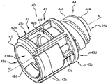
Fig. 3A, 3B, 3C, 3D and 3E are side, two cross-sectional side, perspective and cross-sectional perspective views, respectively, of the rigid outer cap of the end cap assembly of fig. 2A and 2B.
Fig. 4A and 4B are side and perspective views, respectively, of the resilient inner cap of the end cap assembly of fig. 2A and 2B.
Fig. 5 is a theoretical superposition of the rigid outer cap of fig. 3A, 3B and 3C on the elastic inner cap of fig. 4A and 4B.
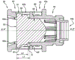
Fig. 6A and 6B are cross-sectional views of an end cap assembly according to an embodiment of the present invention.
Fig. 7 is a cross-sectional view of the end cap assembly mounted to the syringe of fig. 1A,1B and 1C.
Fig. 8 and 9 are perspective views of the syringe of fig. 1A-C closed by end cap assemblies according to two other embodiments of the present invention.
Detailed Description
For purposes of the description hereinafter, the terms "upper", "lower", "right", "left", "vertical", "horizontal", "top", "bottom", "transverse", "longitudinal", and derivatives thereof shall relate to the invention as it is oriented in the drawing figures.
Fig. 1A-1C show an injection system 10 in the form of a luer syringe according to one embodiment of the present invention. The invention may be used with any other form of injection system, such as a pen or infusion system, provided that it has a distal protruding head. For clarity, the present disclosure describes only luer syringe 10. Syringe 10 comprises a longitudinal barrel 11 having a longitudinal axis a, a proximal flange 12 and a distal protruding head 13. The distal protruding head 13 comprises a fluid channel 14 extending therethrough, a distal surface 15 and a substantially tubular side 16 (see fig. 1C). The collar (outer rim) 20 is firmly attached around the head 13, for example by clamping, screwing or welding. In another embodiment (not shown), the collar 20 is molded with the longitudinal barrel, forming a single piece therewith. The collar 20 has an internal thread 21 and a distal rim 22. Syringe 10 further includes a stopper and plunger rod, not shown in fig. 1A-1C.
As shown in fig. 2A-2C, syringe 10 may be hermetically closed by an end cap assembly 30. The end cap assembly 30 includes a rigid outer cap 40 that receives a resilient inner cap 50.
The rigid outer cap 40 will now be described with reference to fig. 3A-3E.
The rigid outer cap 40 comprises a substantially tubular wall 41 having a longitudinal axis a' and defines a cavity 41a open at both the distal and proximal ends. The tubular wall 41 comprises three distinct portions: a distal portion 42, an intermediate portion 43, and a proximal portion 44.
The distal portion 42 has a substantially tubular shape comprising a distal opening 42a and two longitudinal windows 42B (see fig. 3E, only one of which is visible in fig. 3A and 3B), as shown in the example, diametrically opposite. Each window 42b is surrounded on the outside by two longitudinal ribs 42c and one distal radial rib 42d and on the inside by two abutment surfaces 42e and one shoulder 42 f. In other embodiments (not shown), one, three, or four abutment surfaces 42e are provided in the rigid cap 40. A length L1, measured along axis a', is defined between abutment surface 42e and shoulder 42f, constituting the longitudinal dimension of longitudinal window 42 b. The shoulder 42f is located between the distal portion 42 and the intermediate portion 43. In other embodiments (not shown), the distal portion 42 includes one, three, or four windows 42 b.
The intermediate portion 43 has a substantially tubular shape and comprises, on the inside, a plurality of longitudinal edges 43a connected to a shoulder 43 b. On the outside, a ring 43c comprising a proximal abutment surface 43d is connected with the two longitudinal ribs 43e and 42 c. The longitudinal rib 43e extends only partially along the intermediate portion 43, while the longitudinal rib 42c, which surrounds the window 42b, extends partially along the distal portion 42 and the intermediate portion 43. Shoulder 43b is located between intermediate portion 43 and proximal portion 44.
The proximal portion 44 has a frustoconical or frustoconical extension 44 a. The frusto-conical extension 44a includes a proximal opening 44b and three annular ridges 44 c. On the outside, an external thread 44d extends from the ring 43c of the intermediate portion 43 and is separated from the frustoconical extension 44a by a radial groove 44 e. In another embodiment (not shown), the rigid end cap 40 does not have external threads 44d and the proximal section 44 only includes a frustoconical extension 44a having a ridge 44 c. This embodiment can be used with a syringe 10 without the collar 20.
The rigid outer cap may be made from a rigid polymer such as polypropylene, polyethylene, polyvinyl chloride, polystyrene, polycarbonate or a copolymer such as acrylonitrile butadiene styrene or styrene acrylonitrile.
The elastic inner cap 50 will now be described with reference to fig. 4A and 4B. It comprises a distal portion 51 and a proximal portion 52, both having a longitudinal axis a ". Distal portion 51 has a substantially cylindrical shape and a flat distal end face 53. Proximal portion 52 comprises a frustoconical protrusion 54 having a frustoconical shape, a proximal face 55 substantially perpendicular to axis a ", and an annular ridge 56. Proximal portion 52 has a smaller average diameter than distal portion 51, and radial edge 57 is located at the junction of proximal portion 52 and distal portion 51. The truncated cone angle a of the truncated cone forming the truncated cone shaped projection 54 is preferably 40 ° to 60 ° with respect to the axis a ", more preferably 50 ° with respect to the axis a". A length L2 of distal portion 51 measured along axis a "is defined by radial edge 57 and planar distal surface 53. In the embodiment of fig. 4A and 4B, the proximal face 55 is substantially flat. In other embodiments (not shown), the proximal face 55 has a radius of curvature with its center at axis a ". The diameter of the proximal face 55 is preferably greater than the diameter of the fluid passageway 14 of the distal head 13. As can be seen in fig. 4A and 4B, proximal end face 55 is the proximal-most end face of the resilient inner cap 50.
The elastic cap 50 can take three different configurations: a free configuration that is not assembled with the rigid cap 40, a first pressurized configuration assembled into the rigid cap 40 to form the end cap assembly 30, and a second pressurized configuration that applies distal pressure due to the distal protruding head 13 when the end cap assembly 30 closes the fluid passage 14 of the injection system 10, as explained subsequently.
Suitable materials for the elastomeric cap 50 of the present invention include natural rubber, acrylic-butadiene rubber, cis-polybutadiene, chloro or bromo rubber, polyvinyl chloride elastomers, polyalkylene oxide polymers, vinyl acetate, fluorinated silicone rubber, hexafluoroethylene-vinylidene fluoride-tetrafluoroethylene tetramer, butyl rubber, polyisobutylene, synthetic polyisoprene rubber, silicone rubber, styrene-butadiene rubber, tetrafluoroethylene propylene copolymer, thermoplastic-copolyester, thermoplastic-elastomer, and the like, and composites thereof.
The superposition of the cross-sectional views of the elastic inner cap 50 (fig. 4A-4B) and the rigid outer cap 40 (fig. 3A-3E) is shown in fig. 5 as a theoretical diagram, overlapping the shape of the rigid outer cap 40 (at the annular ridge 56) since the schematic shape of the elastic inner cap 50 is freely configured in this figure. Distal portion 51 of flexible inner cap 50 will be received in distal portion 42 of rigid outer cap 40 and proximal portion 52 of flexible inner cap 50 will be received in middle portion 43 of rigid outer cap 40. In the theoretical diagram of fig. 5, axis a' of rigid outer cap 40 coincides with axis a ″ of elastic inner cap 50, and length L1 between abutment surface 42e and shoulder 42f is slightly greater than length L2 of distal portion 51 of elastic inner cap 50. In another embodiment (shown in fig. 7), length L1 is equal to length L2 of distal portion 51. In a last embodiment (not shown), length L1 is slightly shorter than length L2. Finally, annular ridge 56 of flexible inner cap 50 has a diameter slightly larger than the inner diameter of intermediate portion 43 of rigid cap 40.
Fig. 6A and 6B show end cap assembly 30 ready for use with resilient inner cap 50 assembled in rigid cap 40. The elastic inner cap 50 is retained inside the rigid cap 40 and is in a first pressurized configuration: its distal portion 51 is enclosed between the abutment surface 42e and the shoulder 42f of the rigid cap 40 and its longitudinal axis a "coincides with the longitudinal axis a' of the rigid cap 40. The elastic inner cap 50 is interrupted distally by the contact of the distal end surface 53 with the abutment surface 42e of the rigid cap 40 and proximally by the contact of the radial edge 57 with the shoulder 42f of the rigid cap 40. In the embodiment of fig. 6A and 6B, length L1 is greater than length L2, and there is a gap G between rigid cap 40 and resilient cap 50 that allows for limited movement of resilient cap 50 within rigid cap 40. In embodiments where L1 is equal to or less than L2, the abutment surface 42e of the rigid cap 40 is in direct contact with the distal end surface 53 of the resilient inner cap 50, while the shoulder 42f of the rigid cap 40 is in contact with the radial edge 57 of the resilient cap 50. As a result, radial edge 57 contacts shoulder 42f at least when a proximal pressure is applied to elastic inner cap 50, and abutment surface 42e contacts distal surface 53 at least when a distal pressure is applied to elastic inner cap 50. Thus, the abutment surface 42e and the shoulder 42f of the rigid cap 40 together with the distal surface 53 and the radial edge 57 constitute retaining means for firmly fixing the elastic inner cap 50 to the rigid cap 40.
Further, the average diameter of distal portion 51 of flexible inner cap 50 is selected to be slightly larger than the inner diameter of distal portion 42 of rigid cap 40. In this way, after assembly, the elastic inner cap 50 is diametrically tightened, slightly deformed, and a portion of the elastic inner cap 50 even passes through the window 42b of the rigid cap 40 (as shown in fig. 7). This deformation thus increases the contact area of the abutment surface 42e and the distal end face 53 of the elastic inner cap 50. Likewise, as shown in FIG. 5, annular ridge 56 of proximal portion 52 has a diameter slightly larger than the inner diameter of intermediate portion 43 of rigid cap 40. As a result, proximal portion 52 is tightened across its diameter, and frustoconical protrusion 54 is deformed over its length, thus extending further toward proximal portion 44 of rigid cap 40. These deformations further facilitate the retention of the resilient inner cap 50 in the rigid cap 40. In embodiments (not shown) where L1 is smaller than L2, distal portion 51 of elastic cap 50 is secured and slightly deformed over its length.
Due to the particular shapes of the rigid cap 40 and the resilient inner cap 50, the end cap assembly 30 may be obtained by aligning the axis a' of the rigid cap 40 with the axis a "of the resilient inner cap 50, with the proximal portion 52 of the resilient inner cap 50 facing the distal opening 42a of the rigid cap 40. Proximal pressure applied to the resilient inner cap 50 or distal pressure applied to the rigid cap 40 allows the resilient inner cap 50 to enter the rigid cap 40 and deform slightly. This operation may be assisted by lubricating the elastomeric inner cap 50, lubricating the cavity 41a of the rigid cap 40, or both. In embodiments where L1 is greater than L2, gap G allows for greater deformation of elastomeric cap 50 and allows for a greater range of manufacturing tolerances, thereby making assembly simpler. The end cap assembly 30 of this embodiment can therefore be assembled relatively quickly and with a limited probability of incorrect assembly.
As shown in fig. 7, the end cap assembly 30 is ready for connection to the syringe 10. The axes A', A "of the end cap assembly are aligned with the axis A of the syringe 10 and the proximal opening 44b of the end cap assembly 30 is aligned with the distal protruding head 13 of the syringe 10. When the end cap assembly 30 has external threads 44d, a rotational action is required to screw the external threads 44d onto the internal threads 21 of the outer rim 20 of the syringe 10. Before the end of the rotation, the protruding head 13 comes into contact with the proximal face 55 of the elastic inner cap 50. In embodiments where L1 is greater than L2, the elastomeric cap 50 is urged toward the abutment surface 42e of the rigid cap 40 and is further compressed. In embodiments where L1 is equal to or less than L2, the flexible cap 50 has been secured within the rigid cap 40 and is directly compressed by the protruding head 13. Thereafter, the side face 16 of the projecting head 13 comes into contact with the frustoconical extension 44a, which is further deformed radially outwards. At the end of rotation, the proximal abutment surface 43d of the end cap assembly 30 is in contact with the distal rim 22 of the outer rim 20. Thus, the end cap assembly 30 is secured to the rim 20 and to the distally projecting head 13 as shown in FIGS. 2A, 2B and 7. The proximal abutment surface 43d of the rigid cap 40 cooperates with the distal edge 22 of the outer rim 20 to prevent any further rotational movement that could damage the end cap assembly 30. This cooperation also ensures that the end cap 30 is properly positioned relative to the outer rim 20 and provides a tactile indication to the user that the syringe 10 is sealed. In another embodiment (not shown), the proximal abutment surface 43d is not on the ring 43c, but is integrated on the outer surface of the rigid cap 40.
In one embodiment, syringe 10 does not have a rim 20 and end cap assembly 30 accordingly does not have external threads 44d or ring 43c (not shown), end cap assembly 30 being mounted to distal protruding head 13 by proximal movement only.
As shown in fig. 7, the flexible inner cap 50 does not substantially pass through the fluid passageway 14 because the diameter of the proximal face 55 is at least greater than the diameter of the fluid passageway 14. When the end cap assembly 30 is inserted into the head, the resilient inner cap 50 is compressed between the distal protruding head 13 and the abutment surface 42e of the rigid cap 40, which severely deforms the proximal portion 52 of the resilient inner cap 50 to ensure a tight seal of the fluid passage 14. A portion of this deformation is absorbed by the particular shape of the frustoconical projections 54 of the elastic cap 50, contributing to limit the axial and radial stresses transferred to the rigid cap 40. As shown in fig. 7, the deformation of the resilient cap 50 is also partly due to the distal opening 42a and the longitudinal window 42b of the rigid cap 40, further reducing the amount of axial stress transferred to the rigid cap 40 by the abutment surface 42 e. Thus, when the end cap assembly 30 closes the passage 14 of the syringe 10, the frusto-conical projection 54 of the resilient inner cap 50, as well as the distal opening 42a and the longitudinal window 42b of the rigid cap 40, constitute a stress limiting mechanism that allows sufficient deformation of the resilient cap 50. Unwanted deformation of rigid cap 40, and in particular of distal portion 42, is avoided because the stresses cause compression of elastic cap 50 over time: the syringe is stored in a completely sealed manner during the storage period. Thanks to the correct connection of the end-cap assembly to the projecting head 13, the properties or quality, for example the purity, of the fluid stored in the syringe are not altered, even during extended periods of storage. Thus avoiding the waste of valuable fluids and the unacceptable risk to patients and medical staff in contact with the fluids. Thus, the particular geometry of the rigid cap 40, in particular of the distal opening 42a, of the window 42b, of the abutment surface 42e, and of the elastic inner cap 50, in particular of the frustoconical protrusion 54, enables a long-lasting seal of the projecting head 13 of the syringe 10.
The rigid cap 40 is reinforced on its outside by longitudinal ribs 43e, longitudinal ribs 42c and distal radial ribs 42d and on its inside by longitudinal edges 43a and shoulders 43b to resist any deformation caused by the resilient inner cap 50 when the end cap assembly 30 closes the fluid passage 14, or by a user shifting stress when operating the end cap assembly. The longitudinal rib 43e, the longitudinal rib 42c, the distal radial rib 42d, the longitudinal edge 43a and the shoulder 43b thus constitute reinforcing means.
In embodiments where L1 is greater than L2, gap G between rigid cap 40 and flexible cap 50 also serves to enable compatibility with different types of syringes having non-conventional lengths of distal protruding head 13, such as syringes that are not designed to a common standard. The result is that the end cap assembly 30 according to this particular embodiment is able to provide a durable optimum seal even in the case of non-standard syringes.
In the closed position shown in fig. 7, the radial recesses 44e allow limited radial deformation of the frustoconical extension 44a, due to its contact with the side face 16 of the distal projecting head 13. As a result, the frusto-conical extension 44a surrounds and seals the distally projecting head 13, with the three annular ridges 44c in intimate contact with the side surface 16. This ensures that the side wall 16 of the distal head 13 is circumferentially sealed, enabling the sterility of the cavity 41a of the end cap assembly 30 and further the sterility of the protruding head 13 of the syringe 10 to be maintained. In addition to this, the side wall 16 of the distal head 13 is able to seal circumferentially even when the distal head 13 is not perfectly annular. The sterility of the lumen 41a of the end cap assembly 30 is not compromised when the distal head 13 is not sufficiently symmetrical or has an elliptical portion to result in manufacturing tolerances. The frusto-conical extension 44a thus acts as a sterile enclosure during the storage period of the pre-filled syringe, greatly limiting or reducing the ingress of contaminants into the fluid from the syringe head at or prior to injection into a patient. In other embodiments (not shown), the sterile enclosure 44a has at least one annular ridge 44 c.
At the end of storage, a small force is required to unscrew the end cap assembly 30 from the rim 20 to open the fluid passageway 14 of the syringe 10 prior to injecting the stored fluid into a patient. Indeed, the particular shape of the frusto-conical protrusion 54 of the end cap assembly 30 limits the contact area of the resilient cap 50 and the distal protruding head 13 to the distal surface 15, thus avoiding contact of the resilient inner cap 50 and the side surface 16 or the fluid passage 14 of the distal protruding head 13. This greatly reduces or avoids stiction that may occur after long storage periods, thus allowing for quick and easy removal of the end cap assembly 30. The fluid passage 14 is also able to keep the particles clean because the frusto-conical shaped protrusion 54 does not directly contact the inner surface of the fluid passage 14. The frusto-conical protrusion 54 of the resilient inner cap 50 also has a resilient effect on the end cap assembly 30 when the syringe 10 is opened, further facilitating easy removal. Finally, the reinforcing means 43e, 42c, 42d, 43a and 43b also make the wall 41 of the rigid cap 40 thinner. Deformation of the rigid cap 40 during removal can be limited, again ensuring easy removal. The end cap assembly according to the present invention reduces economic losses by preventing disposal of the prefilled syringe prior to use. Further, the injection can be performed in an emergency without great effort. This can save patients who require immediate treatment.
In another embodiment shown in fig. 8, the end cap assembly 100 has the overall shape of an oval cylinder, the outer surface of the rigid cap 140 includes oval reinforcing ridges 141 and 142, the proximal portion (not visible) of the rigid cap 140 is substantially cylindrical and mates with the syringe rim 20, and other configurations are similar to those previously described for the end cap assembly 30 shown in fig. 1-7. End cap assembly 100 is easier to screw on or remove from syringe rim 20 than end cap assembly 30, which is circular cylindrical, because the oval shape provides more contact area with the user's fingers, resulting in better handling.
In another embodiment shown in fig. 9, the end cap assembly 200 has an overall oval cylindrical shape, with a longitudinal reinforcing ridge 241 on the outer surface of the rigid cap 240 surrounding windows 242 (only one of which is visible in fig. 9), and two flat surfaces 243 between the windows 242. The proximal portion (not visible) of the rigid cap 240 is substantially cylindrical and mates with the syringe outer rim 20, with other structure similar to that of the previously described end cap assembly 30 shown in fig. 1-7. End cap assembly 200 is easier to screw on or remove from syringe rim 20 than end cap assembly 30, which is circular cylindrical, because the oval shape provides more contact surface with the user's fingers, resulting in better handling.
In other embodiments (not shown), the end cap assembly 30 may have tamper-evident structure, such as a breakable bump between the rim 20 and the ring 43c of the rigid cap 40. In other embodiments (not shown), the structure of the tamper evidence also includes a security ring on the outer rim 20.
Due to its unique structure, the end cap assembly according to the present invention enables a perfect seal to be maintained for long periods of time, protects the syringe head from contamination during storage and can be opened with little effort.
Claims (13)
1. An end cap assembly (30) for closing a fluid passage (14) of a distal protruding head (13) of a syringe system (10), the end cap assembly (30) comprising:
-an elastic inner cap (50), the elastic inner cap (50) having a proximally extending frusto-conical protrusion (54) with a proximal end face (55), and
-a rigid outer cap (40) firmly or securably arranged around the elastic inner cap (50), the rigid outer cap comprising a substantially tubular wall having a longitudinal axis, the tubular wall comprising a distal portion, an intermediate portion and a proximal portion; the diameter of the proximal face (55) of the frusto-conical projection (54) being at least greater than the diameter of the fluid passage (14) of the syringe system (10);
wherein said proximal end face (55) is a proximal-most end face of said elastic inner cap, intended to come into contact with said distal protruding head (13) to ensure a tight seal of said fluid passage (14); wherein the frusto-conical protrusion (54) is shaped such that contact between the resilient inner cap (50) and the distal protruding head (13) is limited to contact at a distal surface (15) of the distal protruding head (13);
wherein said end cap assembly (30) further has a stress limiting mechanism that allows the elastic inner cap (50) to deform when said end cap assembly closes said fluid passage (14);
wherein the stress limiting mechanism comprises at least one window on the tubular wall of the rigid outer cap (40) and a distal opening (42a) arranged in the rigid outer cap (40);
wherein the inner resilient cap (50) has a proximal end portion (52), the proximal end portion (52) of the inner resilient cap comprising an annular ridge (56), the annular ridge (56) having a diameter greater than an inner diameter of the intermediate portion.
2. The end cap assembly (30) of claim 1, wherein the at least one window comprises two diametrically opposed longitudinal windows (42b) on the rigid outer cap (40).
3. The end cap assembly (30) according to any one of claims 1 to 2, wherein the resilient inner cap (50) and the rigid outer cap (40) comprise a retaining mechanism intended to secure the resilient inner cap (50) in the rigid outer cap (40).
4. The end cap assembly (30) of claim 3, wherein the retaining mechanism comprises a shoulder (42f) in the rigid outer cap (40) and a radial edge (57) on the resilient inner cap (50), the resilient inner cap (50) being blocked proximally by contact between the radial edge (57) and the shoulder (42 f).
5. The end cap assembly (30) of claim 3, wherein the retaining mechanism comprises at least one abutment surface (42e) in the rigid outer cap (40), and a distal end surface (53) on the resilient inner cap (50), the resilient inner cap (50) being distally interrupted by contact between the abutment surface (42e) and the distal end surface (53).
6. The end cap assembly (30) of claim 4, wherein the retaining mechanism comprises at least one abutment surface (42e) in the rigid outer cap (40), and a distal end surface (53) on a resilient inner cap (50), the resilient inner cap (50) being distally interrupted by contact between the abutment surface (42e) and the distal end surface (53).
7. An injection system (10) comprising a longitudinal barrel (11) and a distal protruding head (13), the distal protruding head (13) having a fluid channel (14) therethrough, a distal surface (15) and a side surface (16), wherein the injection system (10) further comprises an end cap assembly (30) according to any of claims 1 to 6.
8. An injection system (10) comprising a longitudinal barrel (11), a distal protruding head (13) and an end cap assembly (30) according to any of claims 1 to 6, the distal protruding head (13) having a fluid passage (14) therethrough, a distal surface (15) and a side surface (16), the end cap assembly (30) being configured such that, when the end cap assembly closes the fluid passage (14), the frusto-conical protrusion (54) contacts the distal protruding head (13) only at the distal surface (15).
9. Injection system according to claim 8, wherein the injection system has a collar (20) firmly fitted around the distally projecting head (13), the collar having an internal thread (21) and a distal edge (22), wherein the rigid outer cap (40) has an external thread (44d) capable of cooperating with the internal thread (21) to close the fluid passage.
10. The injection system of claim 9, wherein the rigid outer cap (40) has a proximal abutment surface (43d), the proximal abutment surface (43d) being in contact with the distal edge (22) of the collar (20) when the end cap assembly (30) closes the fluid channel (14).
11. An injection system (10) comprising:
-a longitudinal cylinder (11),
-a distal protruding head (13),
-a collar (20) with an internal thread (21), said collar (20) being firmly fitted around said distal projecting head (13), said distal projecting head (13) having a lateral face (16) and a fluid passage (14) therethrough, and
-the end cap assembly (30) of any one of claims 1 to 6,
wherein the rigid outer cap (40) of the end cap assembly comprises:
-an external thread (44d) intended to be screwed together with the internal thread (21) of the collar (20),
-a frustoconical extension (44a),
-a radial groove (44e) between said external thread (44d) and said frustoconical extension (44a),
the frusto-conical extension (44a) will ensure a seal around the periphery of the side face (16) of the distal protruding head (13) to act as a sterile enclosure when the end cap assembly (30) closes the fluid passage (14) of the distal protruding head (13).
12. The injection system (10) of claim 11, wherein the frusto-conical extension (44a) has at least one annular ridge (44 c).
13. An end cap assembly (30) for closing a fluid passage (14) of a distal protruding head (13) of a syringe system (10), the end cap assembly (30) comprising:
-a resilient inner cap (50) having a distal end surface (53), a radial edge (57) and a length L2 defined as the distance between the distal end surface (53) and the radial edge (57),
-a rigid outer cap (40) firmly or securely arrangeable around said elastic inner cap (50), said rigid outer cap comprising a substantially tubular wall having a longitudinal axis, said tubular wall comprising a distal portion, an intermediate portion and a proximal portion; the rigid outer cap (40) having a shoulder (42f), at least one abutment surface (42e) and a length L1 defined as the distance between the at least one abutment surface (42e) and the shoulder (42f),
wherein the elastic inner cap (50) is blocked distally by the contact of the distal surface (53) and the at least one abutment surface (42e) and proximally by the contact of the radial edge (57) and the shoulder (42f), and wherein the length L1 is greater than the length L2 to allow limited movement of the elastic inner cap (50) within the rigid outer cap (40);
wherein said end cap assembly (30) further has a stress limiting mechanism that allows the elastic inner cap (50) to deform when said end cap assembly closes said fluid passage (14);
wherein the stress limiting mechanism comprises at least one window on the tubular wall of the rigid outer cap (40) and a distal opening (42a) arranged in the rigid outer cap (40);
wherein the inner resilient cap (50) has a proximal end portion (52), the proximal end portion (52) of the inner resilient cap comprising an annular ridge (56), the annular ridge (56) having a diameter greater than an inner diameter of the intermediate portion.
Applications Claiming Priority (3)
| Application Number | Priority Date | Filing Date | Title |
|---|---|---|---|
| EP20130306414 EP2862587A1 (en) | 2013-10-15 | 2013-10-15 | Tip cap assembly for closing an injection system |
| EP13306414.7 | 2013-10-15 | ||
| CN201410857906.5A CN104548281A (en) | 2013-10-15 | 2014-10-15 | Tip cap assembly for closing an injection system |
Related Parent Applications (1)
| Application Number | Title | Priority Date | Filing Date |
|---|---|---|---|
| CN201410857906.5A Division CN104548281A (en) | 2013-10-15 | 2014-10-15 | Tip cap assembly for closing an injection system |
Publications (1)
| Publication Number | Publication Date |
|---|---|
| CN113842526A true CN113842526A (en) | 2021-12-28 |
Family
ID=49517455
Family Applications (5)
| Application Number | Title | Priority Date | Filing Date |
|---|---|---|---|
| CN202111140079.4A Pending CN113842526A (en) | 2013-10-15 | 2014-10-15 | End cap assembly for closing an injection system |
| CN202110422798.9A Active CN113101464B (en) | 2013-10-15 | 2014-10-15 | End cap assembly for a closed injection system |
| CN201420874047.6U Withdrawn - After Issue CN204798514U (en) | 2013-10-15 | 2014-10-15 | End cap subassembly and injection system thereof |
| CN202110409201.7A Active CN113101461B (en) | 2013-10-15 | 2014-10-15 | End cap assembly for a closed injection system |
| CN201410857906.5A Pending CN104548281A (en) | 2013-10-15 | 2014-10-15 | Tip cap assembly for closing an injection system |
Family Applications After (4)
| Application Number | Title | Priority Date | Filing Date |
|---|---|---|---|
| CN202110422798.9A Active CN113101464B (en) | 2013-10-15 | 2014-10-15 | End cap assembly for a closed injection system |
| CN201420874047.6U Withdrawn - After Issue CN204798514U (en) | 2013-10-15 | 2014-10-15 | End cap subassembly and injection system thereof |
| CN202110409201.7A Active CN113101461B (en) | 2013-10-15 | 2014-10-15 | End cap assembly for a closed injection system |
| CN201410857906.5A Pending CN104548281A (en) | 2013-10-15 | 2014-10-15 | Tip cap assembly for closing an injection system |
Country Status (8)
| Country | Link |
|---|---|
| US (2) | US11013865B2 (en) |
| EP (5) | EP2862587A1 (en) |
| JP (1) | JP6700177B2 (en) |
| KR (3) | KR102642889B1 (en) |
| CN (5) | CN113842526A (en) |
| ES (1) | ES2802925T3 (en) |
| RU (1) | RU2645240C2 (en) |
| WO (1) | WO2015055608A1 (en) |
Families Citing this family (58)
| Publication number | Priority date | Publication date | Assignee | Title |
|---|---|---|---|---|
| US8167847B2 (en) | 2006-06-22 | 2012-05-01 | Excelsior Medical Corporation | Antiseptic cap and antiseptic cap equipped plunger and syringe barrel assembly |
| US9259535B2 (en) | 2006-06-22 | 2016-02-16 | Excelsior Medical Corporation | Antiseptic cap equipped syringe |
| US11229746B2 (en) | 2006-06-22 | 2022-01-25 | Excelsior Medical Corporation | Antiseptic cap |
| US9700710B2 (en) | 2006-06-22 | 2017-07-11 | Excelsior Medical Corporation | Antiseptic cap equipped syringe |
| US9078992B2 (en) | 2008-10-27 | 2015-07-14 | Pursuit Vascular, Inc. | Medical device for applying antimicrobial to proximal end of catheter |
| WO2012162259A2 (en) | 2011-05-20 | 2012-11-29 | Excelsior Medical Corporation | Caps for cannula access devices |
| US10166381B2 (en) | 2011-05-23 | 2019-01-01 | Excelsior Medical Corporation | Antiseptic cap |
| US9867975B2 (en) | 2011-05-23 | 2018-01-16 | Excelsior Medical Corporation | Antiseptic line cap |
| ES2797649T3 (en) | 2011-07-12 | 2020-12-03 | Icu Medical Inc | Device for the delivery of antimicrobial agent in a transdermal catheter |
| EP2862587A1 (en) * | 2013-10-15 | 2015-04-22 | Becton Dickinson France | Tip cap assembly for closing an injection system |
| US10046156B2 (en) | 2014-05-02 | 2018-08-14 | Excelsior Medical Corporation | Strip package for antiseptic cap |
| WO2016182822A1 (en) | 2015-05-08 | 2016-11-17 | Icu Medical, Inc. | Medical connectors configured to receive emitters of therapeutic agents |
| JP6779241B2 (en) * | 2015-06-12 | 2020-11-04 | ベクトン ディキンソン フランス | Adapters and drug delivery devices for drug delivery devices |
| US10039913B2 (en) | 2015-07-30 | 2018-08-07 | Carefusion 303, Inc. | Tamper-resistant cap |
| EP3269418A1 (en) | 2016-07-12 | 2018-01-17 | Becton Dickinson France | Tip cap assembly, medical injection system and process for producing a medical injection system |
| US11850778B2 (en) * | 2016-10-04 | 2023-12-26 | Gerresheimer Regensburg Gmbh | Method for producing a syringe with an integrated closure element |
| DK3525865T3 (en) | 2016-10-14 | 2022-10-24 | Icu Medical Inc | Disinfectant caps for medical connectors |
| IL311121A (en) | 2017-03-27 | 2024-04-01 | Regeneron Pharma | Sterilisation method |
| SG11201909600XA (en) * | 2017-04-19 | 2019-11-28 | Baxter Int | Non-clogging dispensing device |
| WO2018204206A2 (en) | 2017-05-01 | 2018-11-08 | Icu Medical, Inc. | Medical fluid connectors and methods for providing additives in medical fluid lines |
| CN111225700A (en) * | 2017-10-06 | 2020-06-02 | 诺信公司 | Tamper-evident closure assembly |
| CN111491680B (en) | 2017-12-13 | 2023-08-29 | 里珍纳龙药品有限公司 | Device and method for accurate dose delivery |
| WO2019123488A1 (en) * | 2017-12-19 | 2019-06-27 | Matex Lab S.P.A. | Cartridge for a syringe, and corresponding syringe |
| WO2019123489A1 (en) * | 2017-12-19 | 2019-06-27 | Matex Lab S.P.A. | Cartridge for a syringe, and corresponding syringe |
| US11541180B1 (en) | 2017-12-21 | 2023-01-03 | Patrick Vitello | Closure assembly having a snap-fit construction |
| US20190231985A1 (en) * | 2018-01-26 | 2019-08-01 | Becton, Dickinson And Company | Flush Syringe With Shielded Tip |
| EP3520846A1 (en) * | 2018-01-31 | 2019-08-07 | Becton Dickinson France | Protection device for a needle |
| US11278681B1 (en) | 2018-02-20 | 2022-03-22 | Robert Banik | Tamper evident adaptor closure |
| US11413406B1 (en) | 2018-03-05 | 2022-08-16 | Jonathan J. Vitello | Tamper evident assembly |
| US11793987B1 (en) | 2018-07-02 | 2023-10-24 | Patrick Vitello | Flex tec closure assembly for a medical dispenser |
| US11857751B1 (en) * | 2018-07-02 | 2024-01-02 | International Medical Industries Inc. | Assembly for a medical connector |
| US11779520B1 (en) | 2018-07-02 | 2023-10-10 | Patrick Vitello | Closure for a medical dispenser including a one-piece tip cap |
| US11690994B1 (en) | 2018-07-13 | 2023-07-04 | Robert Banik | Modular medical connector |
| US11426328B1 (en) | 2018-08-31 | 2022-08-30 | Alexander Ollmann | Closure for a medical container |
| ES2959943T3 (en) * | 2018-10-05 | 2024-02-29 | Becton Dickinson France | Cover cap remover with sealing gasket compression |
| US11471610B1 (en) | 2018-10-18 | 2022-10-18 | Robert Banik | Asymmetrical closure for a medical device |
| USD948713S1 (en) | 2019-09-03 | 2022-04-12 | International Medical Industries, Inc. | Asymmetrical self righting tip cap |
| US11541221B2 (en) | 2018-11-07 | 2023-01-03 | Icu Medical, Inc. | Tubing set with antimicrobial properties |
| US11400195B2 (en) | 2018-11-07 | 2022-08-02 | Icu Medical, Inc. | Peritoneal dialysis transfer set with antimicrobial properties |
| US11517732B2 (en) | 2018-11-07 | 2022-12-06 | Icu Medical, Inc. | Syringe with antimicrobial properties |
| US11541220B2 (en) | 2018-11-07 | 2023-01-03 | Icu Medical, Inc. | Needleless connector with antimicrobial properties |
| US11534595B2 (en) | 2018-11-07 | 2022-12-27 | Icu Medical, Inc. | Device for delivering an antimicrobial composition into an infusion device |
| EP3883638A1 (en) | 2018-11-21 | 2021-09-29 | ICU Medical, Inc. | Antimicrobial device comprising a cap with ring and insert |
| MA54325A (en) | 2019-06-05 | 2022-05-11 | Regeneron Pharma | DEVICES AND METHODS FOR ACCURATE DOSE DELIVERY |
| US11911339B1 (en) | 2019-08-15 | 2024-02-27 | Peter Lehel | Universal additive port cap |
| US11697527B1 (en) | 2019-09-11 | 2023-07-11 | Logan Hendren | Tamper evident closure assembly |
| US11357588B1 (en) | 2019-11-25 | 2022-06-14 | Patrick Vitello | Needle packaging and disposal assembly |
| USD938024S1 (en) * | 2020-02-03 | 2021-12-07 | Becton Dickinson France | Injector shield |
| USD944977S1 (en) * | 2020-02-03 | 2022-03-01 | Becton Dickinson France | Injector shield |
| US11904149B1 (en) | 2020-02-18 | 2024-02-20 | Jonathan Vitello | Oral tamper evident closure with retained indicator |
| US11523970B1 (en) | 2020-08-28 | 2022-12-13 | Jonathan Vitello | Tamper evident shield |
| WO2022051470A1 (en) * | 2020-09-02 | 2022-03-10 | Nephron Pharmaceuticals Corporation | Tamper-evident cap |
| EP4255552A1 (en) | 2020-12-07 | 2023-10-11 | ICU Medical, Inc. | Peritoneal dialysis caps, systems and methods |
| US11872187B1 (en) | 2020-12-28 | 2024-01-16 | Jonathan Vitello | Tamper evident seal for a vial cover |
| IT202100003320A1 (en) * | 2021-02-15 | 2022-08-15 | Platinum Pharma Service S R L S | SYRINGE CAP WITH LUER-LOCK ATTACHMENT |
| WO2023176064A1 (en) * | 2022-03-18 | 2023-09-21 | テルモ株式会社 | Outer cylinder for syringe, syringe, and prefilled syringe |
| EP4316550A1 (en) * | 2022-08-04 | 2024-02-07 | Becton Dickinson France | Tip cap assembly for an injection system |
| KR102648195B1 (en) | 2023-08-09 | 2024-03-15 | (주)이젠텍 | Openable cap |
Citations (5)
| Publication number | Priority date | Publication date | Assignee | Title |
|---|---|---|---|---|
| US4597758A (en) * | 1982-09-21 | 1986-07-01 | Baxter Travenol Laboratories, Inc. | Sealing closure for a Luer fitting in open communication with a pressurized liquid supply |
| US6520935B1 (en) * | 1994-12-12 | 2003-02-18 | Becton, Dickinson And Company | Syringe and tip cap assembly |
| US20030171719A1 (en) * | 2002-03-07 | 2003-09-11 | Veillon Joseph N. | Luer tip cap having reduced removal force |
| JP2009240684A (en) * | 2008-03-31 | 2009-10-22 | Terumo Corp | Method for manufacturing cap and prefilled syringe |
| JP2013078442A (en) * | 2011-10-03 | 2013-05-02 | Taisei Kako Co Ltd | Cap, barrel with cap, and prefilled syringe |
Family Cites Families (298)
| Publication number | Priority date | Publication date | Assignee | Title |
|---|---|---|---|---|
| US2723041A (en) | 1951-04-09 | 1955-11-08 | Hart-Still Sydney Charles | Closure for bottles and other containers |
| US2812763A (en) | 1956-07-17 | 1957-11-12 | Becton Dickinson Co | Syringe assembly |
| US3055363A (en) | 1959-11-18 | 1962-09-25 | Becton Dickinson Co | Hypodermic syringe barrel assembly |
| US3112747A (en) | 1961-02-07 | 1963-12-03 | Pharmaseal Lab | Protector |
| DK108590C (en) | 1964-05-28 | 1968-01-08 | Novo Terapeutisk Labor As | Spray ampoule. |
| US3380448A (en) | 1964-11-24 | 1968-04-30 | Abbott Lab | Cervical-pudendal indwelling catheter set with tissue piercing means |
| US3381813A (en) | 1965-09-07 | 1968-05-07 | Pharmaseal Lab | Hypodermic needle and protector therefor |
| US3390759A (en) | 1967-05-25 | 1968-07-02 | Becton Dickinson Co | Shield and hub for disposable needle |
| US3847183A (en) | 1972-11-22 | 1974-11-12 | V Meyer | Closure |
| US3865236A (en) | 1973-03-16 | 1975-02-11 | Becton Dickinson Co | Needle shield |
| DE2434046C3 (en) | 1974-07-16 | 1979-10-18 | Lothar 7500 Karlsruhe Schwarz | Needle holder for medical syringes |
| US4240427A (en) | 1978-10-23 | 1980-12-23 | American Hospital Supply Corporation | Needle with protector |
| US4240425A (en) | 1978-10-23 | 1980-12-23 | American Hospital Supply Corporation | Syringe with plug type needle hub lock |
| DK148782C (en) | 1980-10-31 | 1986-04-21 | Radiometer As | PROCEDURE AND CLOSURE CAP FOR ANAEROBIC SEALING OF A BLOOD TEST CAPILLAR |
| FI832099L (en) | 1982-06-15 | 1983-12-16 | Intermedicat Gmbh | BELUFTNINGSFILTER |
| US4452473A (en) | 1982-07-26 | 1984-06-05 | Baxter Travenol Laboratories, Inc. | Luer connection system |
| SE437348B (en) | 1983-07-29 | 1985-02-25 | Pharmacia Ab | CLOSING DEVICE FOR THE FLUID DUMP CONNECTION OF AN OPENING OF A FLUIDUM CONTAINER OR FLUIDUM PIPE |
| WO1988000479A1 (en) | 1986-07-11 | 1988-01-28 | Arzneimittel Gmbh Apotheker Vetter & Co. Ravensbur | Syringe for medicinal purposes |
| US4753345A (en) | 1984-06-14 | 1988-06-28 | American Home Products Corporation | Hypodermic syringe tray |
| US4836397A (en) | 1984-11-13 | 1989-06-06 | Baxter International Inc. | Closure for sealing a port |
| DE3515665C1 (en) | 1985-05-02 | 1986-05-15 | Gerhard 6393 Wehrheim Pfetzing | Closure plug |
| US4826490A (en) | 1985-07-29 | 1989-05-02 | National Research Development Corporation | Safety device for hypodermic needle or the like |
| US4636201A (en) | 1985-11-01 | 1987-01-13 | American Hospital Supply Corporation | Hypodermic syringe having a protective sheath cover |
| US4628969A (en) | 1985-12-20 | 1986-12-16 | Mallinckrodt, Inc. | Method of producing prefilled sterile plastic syringes |
| US4718463A (en) | 1985-12-20 | 1988-01-12 | Mallinckrodt, Inc. | Method of producing prefilled sterile plastic syringes |
| US4735311A (en) | 1986-04-09 | 1988-04-05 | The West Company | Needle shield assembly |
| US4765588A (en) | 1986-08-18 | 1988-08-23 | Vernay Laboratories, Inc. | Check valve for use with a syringe |
| US4850970A (en) | 1987-03-26 | 1989-07-25 | American Home Products, Corp. | Two part mastitis cannula cap |
| GB2249727A (en) | 1989-11-16 | 1992-05-20 | Duoject Inc | Syringe vial |
| EP0309426A3 (en) | 1987-09-25 | 1991-04-03 | INDUSTRIE BORLA S.p.A. | A gas-tight closure device for the connecting ends of tubes for biomedical fluid-transporting apparatus, particularly haemodialysis lines, which are sterilised by means of sterilising gas |
| US4935012A (en) | 1988-06-10 | 1990-06-19 | George R. Magre | Safety device for medical needles |
| US4915704A (en) | 1988-06-27 | 1990-04-10 | Terumo Kabushiki Kaisha | Tube assembly with a breakaway plug |
| JP2505871B2 (en) | 1988-11-14 | 1996-06-12 | 株式会社ニッショー | Communication tool when used |
| US4892222A (en) | 1988-11-25 | 1990-01-09 | Baxter International Inc. | Port assembly for a container |
| US5009640A (en) | 1989-01-19 | 1991-04-23 | The Upjohn Company | Slip cap for cannula use |
| US5104379A (en) * | 1989-04-03 | 1992-04-14 | Olympus Optical Co., Ltd. | Medical instrument and valve to be mounted on a mount piece of that instrument |
| ATE108675T1 (en) * | 1989-05-17 | 1994-08-15 | Vetter & Co Apotheker | SYRINGE FOR MEDICAL PURPOSES. |
| US4986818A (en) | 1990-03-30 | 1991-01-22 | Becton, Dickinson And Company | Syringe assembly |
| US5184742A (en) * | 1990-06-18 | 1993-02-09 | Boc Health Care, Inc. | Deadender cap for luer fitting |
| US5125415A (en) | 1990-06-19 | 1992-06-30 | Smiths Industries Medical Systems, Inc. | Syringe tip cap with self-sealing filter |
| US5088995A (en) | 1990-06-22 | 1992-02-18 | Baxter International Inc. | Port and closure assembly including a resealing injection site for a container |
| US5167642A (en) | 1990-08-27 | 1992-12-01 | Baxter International Inc. | Sheath for a blunt cannula |
| DK228290D0 (en) | 1990-09-21 | 1990-09-21 | Novo Nordisk As | AND INJECTION UNIT |
| US5069424A (en) | 1990-10-17 | 1991-12-03 | Itt Corporation | Quick connector |
| US5098400A (en) | 1991-02-14 | 1992-03-24 | Sherwood Medical Company | Needle shield |
| DE9105229U1 (en) | 1991-04-27 | 1991-06-13 | B. Braun Melsungen Ag, 3508 Melsungen, De | |
| US5224515A (en) | 1992-01-30 | 1993-07-06 | Porex Technologies Corp. | Tube closure |
| US5593391A (en) | 1992-02-13 | 1997-01-14 | Stanners; Sydney D. | Ampule safety syringe |
| AR246435A1 (en) | 1992-08-20 | 1994-08-31 | Moreno Saul | Disposable syringe for use with a needle sheath. |
| US5509911A (en) | 1992-11-27 | 1996-04-23 | Maxxim Medical, Inc. | Rotating adapter for a catheterization system |
| US5373684A (en) | 1992-12-14 | 1994-12-20 | Mallinckrodt Medical, Inc. | Process and apparatus used in producing prefilled, sterile delivery devices |
| WO1994023775A1 (en) | 1993-03-23 | 1994-10-27 | Abbott Laboratories | Securing collar for cannula connector |
| US5540666A (en) | 1993-03-31 | 1996-07-30 | Immuno Aktiengesellschaft | Cannula shield and injection syringe system |
| US5591143A (en) | 1993-04-02 | 1997-01-07 | Medrad Inc. | Luer connector with torque indicator |
| US5395348A (en) | 1993-05-04 | 1995-03-07 | Symbiosis Corporation | Medical intravenous administration line connectors |
| DE4318101A1 (en) | 1993-06-01 | 1994-12-08 | Sterimed Gmbh | Hose coupling |
| US5634903A (en) | 1993-07-09 | 1997-06-03 | Terumo Kabushiki Kaisha | Syringe assembly |
| US5447500A (en) | 1993-09-29 | 1995-09-05 | Sterling Winthrop, Inc. | Collar and cartridge-needle unit assembly |
| US5419775A (en) | 1994-01-18 | 1995-05-30 | Allergan, Inc. | Syringe flange adapter and method |
| JP2901483B2 (en) * | 1994-03-16 | 1999-06-07 | 株式会社アルテ | Syringe |
| US7033339B1 (en) | 1998-05-29 | 2006-04-25 | Becton Dickinson And Company (Part Interest) | Self sealing luer receiving stopcock |
| JP3383966B2 (en) | 1994-05-27 | 2003-03-10 | ニプロ株式会社 | Prefilled syringe |
| DE4434644C2 (en) * | 1994-09-28 | 1997-08-07 | Schott Glaswerke | Container for the storage and administration of injection, infusion and diagnostic preparations |
| ZA958073B (en) | 1994-09-28 | 1996-04-23 | Anthony William Manicom | Method of and apparatus for administering a drug to a patient |
| AUPM922394A0 (en) | 1994-11-03 | 1994-11-24 | Astra Pharmaceuticals Pty Ltd | Plastic syringe with overcap |
| US5624402A (en) | 1994-12-12 | 1997-04-29 | Becton, Dickinson And Company | Syringe tip cap |
| JP3208525B2 (en) | 1995-01-05 | 2001-09-17 | 電気化学工業株式会社 | Sodium hyaluronate solution injection and container for injection |
| US5531710A (en) | 1995-02-24 | 1996-07-02 | Courtaulds Aerospace, Inc. | Combination closure and syringe |
| US5658254A (en) | 1995-03-31 | 1997-08-19 | Becton, Dickinson And Company | Syringe having safety needle shield |
| IT235830Y1 (en) | 1995-04-06 | 2000-07-18 | Borla Ind | "LUER-LOCK FITTING WITH PROTECTION CAP FOR MEDICATION LINES-INFUSION-TRANSFUSION." |
| US5607400A (en) | 1995-05-19 | 1997-03-04 | Becton, Dickinson And Company | Pre-fillable syringe and stopper assembly therefor |
| JP3647958B2 (en) | 1995-06-16 | 2005-05-18 | 株式会社アルテ | Container / Syringe |
| US5807345A (en) | 1995-06-30 | 1998-09-15 | Abbott Laboratories | Luer cap for terminally sterilized syringe |
| US5693025A (en) | 1995-07-14 | 1997-12-02 | Merit Medical Systems, Inc. | Adapter with hemostasis valve and rotatable connector |
| DE19547431A1 (en) * | 1995-12-05 | 1997-06-12 | Schering Ag | Closure system for a sterile syringe |
| US5836919A (en) | 1996-05-23 | 1998-11-17 | Solopak Pharmaceuticals, Inc. | Cap assembly |
| SE513823C2 (en) | 1996-05-31 | 2000-11-13 | Wiklund Ernst S G F | Point guard for puncture needles |
| US5820604A (en) | 1996-06-11 | 1998-10-13 | Endolap, Inc. | Cannula cap including yeildable outer seal and flapper valve |
| US5858008A (en) | 1997-04-22 | 1999-01-12 | Becton, Dickinson And Company | Cannula sealing shield assembly |
| US7789864B2 (en) | 1996-11-18 | 2010-09-07 | Nypro Inc. | Luer-activated valve |
| US20020013556A1 (en) | 1996-11-18 | 2002-01-31 | Cote Andrew L. | Swabbable luer-activated valve |
| DE19652708C2 (en) | 1996-12-18 | 1999-08-12 | Schott Glas | Process for producing a filled plastic syringe body for medical purposes |
| CA2227942A1 (en) | 1997-01-31 | 1998-07-31 | Becton, Dickinson And Company | Adapter for mounting a fluid handling device on a catheter tubing |
| JP3380705B2 (en) | 1997-03-12 | 2003-02-24 | 株式会社大協精工 | Sealed rubber stopper for syringe and container |
| US5820621A (en) | 1997-07-29 | 1998-10-13 | Becton, Dickinson And Company | Medical fluid transfer and delivery device |
| US6029946A (en) | 1997-09-15 | 2000-02-29 | Tiva Medical Inc. | Needleless valve |
| US6004296A (en) | 1997-09-30 | 1999-12-21 | Becton Dickinson France, S.A. | Lockable safety shield assembly for a prefillable syringe |
| DE19751219A1 (en) | 1997-11-19 | 1999-05-27 | Vetter & Co Apotheker | Syringe, especially prefilled syringe, or carpule |
| EP1080742B1 (en) | 1998-03-27 | 2005-12-14 | Bracco International B.V. | Plastic syringe barrel and method of improving it |
| US6361524B1 (en) | 1998-04-14 | 2002-03-26 | Becton, Dickinson And Company | Syringe assembly |
| EP0976415B1 (en) | 1998-07-31 | 2005-05-11 | Becton, Dickinson and Company | A needle shield for a prefillable syringe |
| US6261270B1 (en) | 1998-09-23 | 2001-07-17 | Abbott Laboratories | Sleeve stopper |
| US6394983B1 (en) | 1998-10-28 | 2002-05-28 | Abbott Laboratories | Cap and luer connector for a fluid transfer device |
| DE19909824A1 (en) * | 1999-03-05 | 2000-09-07 | Vetter & Co Apotheker | Syringe for medical purposes and assembly method |
| US6716396B1 (en) | 1999-05-14 | 2004-04-06 | Gen-Probe Incorporated | Penetrable cap |
| US6706022B1 (en) | 1999-07-27 | 2004-03-16 | Alaris Medical Systems, Inc. | Needleless medical connector with expandable valve mechanism |
| DE19954373B4 (en) | 1999-11-11 | 2011-01-27 | Helvoet Pharma Belgium N.V. | Protective cap for a cannula |
| US6652509B1 (en) | 2000-04-03 | 2003-11-25 | Abbott Laboratories | Housing capable of connecting a container to a medical device |
| US6632199B1 (en) | 2000-05-23 | 2003-10-14 | Becton Dickinson And Company | Syringe assembly including plastic tip cap |
| WO2001089611A1 (en) | 2000-05-25 | 2001-11-29 | Johnson Johnnie M | Adapter and method of attachment for 'luer lok' receptacles |
| US6375022B1 (en) | 2000-06-30 | 2002-04-23 | Becton, Dickinson And Company | Resealable closure for containers |
| US7316669B2 (en) | 2002-08-22 | 2008-01-08 | Baxa Corporation | Protective cap for medical male luer fittings |
| ES2185534T3 (en) | 2000-09-27 | 2003-05-01 | Schering Ag | SYRINGE WITH A CYLINDER THAT HOUSES A HALF FLUID AND WITH A CLOSING CAP. |
| JP2002153539A (en) | 2000-11-16 | 2002-05-28 | Asahi Medical Co Ltd | Lure plug body for medical instrument and medical instrument with the same |
| FR2816848B1 (en) | 2000-11-17 | 2003-06-20 | Rumpler Technologies | PROTECTION DEVICE FOR SYRINGE NEEDLE |
| US20050187524A1 (en) | 2000-12-19 | 2005-08-25 | Willis Allan F. | Sealing valve assembly for medical products |
| US6595964B2 (en) | 2000-12-22 | 2003-07-22 | Baxter International Inc. | Luer activated thread coupler |
| US7316679B2 (en) | 2001-01-22 | 2008-01-08 | Venetec International, Inc. | Medical device connector fitting |
| US6585691B1 (en) | 2001-05-11 | 2003-07-01 | Jonathan J. Vitello | Tamper evident end cap assembly for a loaded syringe and process |
| DE10127779A1 (en) * | 2001-06-01 | 2002-12-12 | Vetter & Co Apotheker | Twist closure for primary packaging of pharmaceuticals, comprising channels between closure parts to allow flow of sterilizing vapor to closure contact surfaces |
| JP2003054615A (en) * | 2001-06-07 | 2003-02-26 | Sumitomo Pharmaceut Co Ltd | Seaming lid, and vessel using the same |
| GB2410305B (en) | 2001-09-04 | 2005-12-07 | Clinical Product Dev Ltd | Couplings for medical fluid delivery systems |
| US7563249B2 (en) | 2002-12-20 | 2009-07-21 | Medrad, Inc. | Syringe having an alignment flange, an extending lip and a radial expansion section of reduced wall thickness |
| US6802490B2 (en) | 2001-11-29 | 2004-10-12 | Alaris Medical Systems, Inc. | Needle free medical connector with expanded valve mechanism and method of fluid flow control |
| FR2833175B1 (en) | 2001-12-06 | 2004-05-14 | Sobem | FLOW CONTROL DEVICE FOR MEDICAL USE |
| US6651956B2 (en) | 2002-01-31 | 2003-11-25 | Halkey-Roberts Corporation | Slit-type swabable valve |
| FR2836832B1 (en) | 2002-03-08 | 2005-02-04 | Optis France Sa | CONNECTION ASSEMBLY FOR MEDICAL USE FOR THE TRANSFER OF FLUIDS |
| US7244249B2 (en) | 2002-05-08 | 2007-07-17 | Cardinal Health 303, Inc. | Needle-free medical connector with expandable valve mechanism and method of fluid flow control |
| JP4427965B2 (en) | 2002-07-02 | 2010-03-10 | ニプロ株式会社 | Chemical container with communication means |
| ITTO20020668A1 (en) | 2002-07-26 | 2004-01-26 | Borla Ind | CANNULA WITH PROTECTION CAP FOR MEDICAL INFUSION LINES |
| JP4425140B2 (en) | 2002-09-03 | 2010-03-03 | メディカル・インスティル・テクノロジーズ・インコーポレイテッド | Liquid medicine bottle assembly |
| US8377039B2 (en) | 2002-10-04 | 2013-02-19 | Nxstage Medical, Inc. | Injection site for male luer or other tubular connector |
| US7056308B2 (en) | 2002-10-04 | 2006-06-06 | Dsu Medical Corporation | Medical device with elastomeric penetrable wall and inner seal |
| DE10247963A1 (en) | 2002-10-15 | 2004-05-06 | Transcoject Gesellschaft für medizinische Geräte mbH & Co KG | Pre-filled syringe with membrane seal, has cylinder, connector and sealing membrane constructed in one piece as plastic injection-molded part |
| DE10247965A1 (en) | 2002-10-15 | 2004-05-06 | Transcoject Gesellschaft für medizinische Geräte mbH & Co KG | Tamper-evident closure for a syringe |
| GB0224505D0 (en) | 2002-10-22 | 2002-11-27 | Medical House The Plc | Needles injection device |
| JP4491215B2 (en) | 2003-10-06 | 2010-06-30 | テルモ株式会社 | Prefilled syringe and method for producing prefilled syringe |
| JP4522071B2 (en) | 2002-10-24 | 2010-08-11 | テルモ株式会社 | Syringe |
| US8025646B2 (en) | 2003-01-09 | 2011-09-27 | Fukai Kogyo Kabushiki Kaisha | Seal valve, connection port, mix-feed tube, connection device for liquid infusion circuit, and connection system for liquid infusion circuit that are for medical device |
| US7338474B2 (en) * | 2003-02-18 | 2008-03-04 | Tribute Technologies, Llc | Luer attachment for syringe safety |
| US7118560B2 (en) | 2003-02-28 | 2006-10-10 | Creative Plastic Technology, Llc | Needleless Luer activated medical connector |
| USD493526S1 (en) | 2003-04-22 | 2004-07-27 | Becton, Dickinson And Company | Syringe tip cap |
| DE10340613A1 (en) | 2003-08-29 | 2005-03-24 | Primojex Gmbh | Device for injecting an injectable product |
| US20050063857A1 (en) | 2003-09-23 | 2005-03-24 | Alheidt Thomas A. | Flush syringe having anti-reflux stopper |
| US20050075611A1 (en) | 2003-10-01 | 2005-04-07 | Hetzler Kevin G. | Low extractable, thermoplastic syringe and tip cap |
| US20060129109A1 (en) | 2003-10-28 | 2006-06-15 | Scott Randall Shaw | Reconnectable disconnect device for fluid transfer line |
| HK1077154A2 (en) | 2003-12-30 | 2006-02-03 | Vasogen Ireland Ltd | Valve assembly |
| US7497843B1 (en) | 2004-03-12 | 2009-03-03 | Medrad, Inc. | Syringe interfaces, syringe adapters and injector systems |
| CA2605968C (en) | 2004-04-23 | 2011-07-05 | Coeur, Inc. | Syringe adapter system and method of cleaning the adapter |
| DK1600190T3 (en) * | 2004-05-29 | 2007-12-27 | Gerresheimer Buende Gmbh | Syringe closure device and method for manufacturing a syringe closure device |
| US20140276459A1 (en) | 2013-03-13 | 2014-09-18 | Jonathan Yeh | Needleless connector with folding valve |
| ES2380911T3 (en) | 2004-11-05 | 2012-05-21 | Icu Medical, Inc. | Medical connector that has high flow characteristics |
| DE102004055453A1 (en) | 2004-11-17 | 2006-05-24 | Schering Ag | originality closure |
| US7645274B2 (en) | 2004-12-10 | 2010-01-12 | Cardinal Health 303, Inc. | Self-sealing male luer connector with multiple seats |
| US7396051B2 (en) | 2005-01-14 | 2008-07-08 | Baxa Corporation | Swabable fluid connectors and fluid connector pairs |
| CA2597586C (en) | 2005-02-14 | 2014-12-09 | Gilero, Llc | Valved fluid connector |
| WO2006096960A1 (en) | 2005-03-15 | 2006-09-21 | Vasogen Ireland Limited | Controlled flow adapter for medical fluid containers |
| DE502005005947D1 (en) | 2005-03-24 | 2008-12-24 | Disetronic Licensing Ag | Device for the dosed administration of a fluid product |
| US7998134B2 (en) | 2007-05-16 | 2011-08-16 | Icu Medical, Inc. | Medical connector |
| US7803139B2 (en) | 2005-07-06 | 2010-09-28 | Icu Medical, Inc. | Medical connector with closeable male luer |
| EP1909735A1 (en) | 2005-08-01 | 2008-04-16 | Medimop Medical Projects Ltd. | Liquid drug delivery system |
| EP1759729B1 (en) | 2005-08-30 | 2009-12-23 | Cilag GmbH International | Needle assembly for a prefilled syringe system |
| JP4555766B2 (en) * | 2005-10-19 | 2010-10-06 | 株式会社アルテ | Container / Syringe |
| JP4943690B2 (en) | 2005-10-27 | 2012-05-30 | 前田産業株式会社 | Syringe holder and syringe |
| DE102005052545A1 (en) | 2005-11-02 | 2007-05-03 | Schering Ag | Closure for medical syringe, has syringe cylinder and connected syringe neck at distal end whereby syringe neck has fixable adapter in which screw cap is fixable |
| DE102005054075A1 (en) | 2005-11-12 | 2007-05-16 | Vetter & Co Apotheker | Needle attachment for a syringe or carpule |
| US8377010B2 (en) | 2005-11-17 | 2013-02-19 | Becton, Dickinson And Company | Medical access device |
| FR2896168B1 (en) | 2006-01-19 | 2008-10-17 | Aguettant Soc Par Actions Simp | PRE-FILLED HYPODERMIC SYRINGE EQUIPPED WITH A CLOGGING DEVICE |
| US20070225647A1 (en) | 2006-03-23 | 2007-09-27 | Luther Ronald B | Flush entrance hemostasis valve with unobstructed passageway |
| JP5161457B2 (en) | 2006-04-03 | 2013-03-13 | 日本コヴィディエン株式会社 | Male luer connector |
| US9295790B2 (en) | 2006-05-05 | 2016-03-29 | Retractable Technologies, Inc. | Syringe with recessed nose and protective guard for use with frontal attachments |
| US8162899B2 (en) | 2006-05-18 | 2012-04-24 | Hyprotek, Inc. | Intravascular line and port cleaning methods, methods of administering an agent intravascularly, methods of obtaining/testing blood, and devices for performing such methods |
| GB2438593B (en) | 2006-06-01 | 2011-03-30 | Cilag Gmbh Int | Injection device (cap removal feature) |
| EP2223868B1 (en) | 2006-06-13 | 2012-02-01 | Nordson Corporation | Liquid dispensing syringe |
| US8167847B2 (en) | 2006-06-22 | 2012-05-01 | Excelsior Medical Corporation | Antiseptic cap and antiseptic cap equipped plunger and syringe barrel assembly |
| WO2008010958A2 (en) | 2006-07-18 | 2008-01-24 | Mallinckrodt Inc. | Breakage resistant luer fitting |
| US10881847B2 (en) | 2006-08-09 | 2021-01-05 | Lawrence Allan Lynn | Neutral pressure split septum luer access device |
| US7632244B2 (en) * | 2006-08-10 | 2009-12-15 | Comar, Inc. | Tamper evident tip cap assembly |
| US7753338B2 (en) | 2006-10-23 | 2010-07-13 | Baxter International Inc. | Luer activated device with minimal fluid displacement |
| JP4895767B2 (en) | 2006-11-15 | 2012-03-14 | 株式会社アルテ | Luer lock tube tip of syringe |
| JP2008125560A (en) | 2006-11-16 | 2008-06-05 | Daikyo Seiko Ltd | Syringe nozzle cap |
| FR2910817B1 (en) | 2007-01-03 | 2009-02-13 | Vygon Sa | CONNECTOR FOR ESTABLISHING A FLUID COMMUNICATION UNDER THE CONTROL OF A VALVE, IN PARTICULAR FOR USE IN THE MEDICAL FIELD |
| US7935091B2 (en) | 2007-01-16 | 2011-05-03 | Bousquet Gerald G | Catheter extension set and closure assembly therefor |
| US8343112B2 (en) * | 2009-10-30 | 2013-01-01 | Catheter Connections, Inc. | Disinfecting caps having an extendable feature and related systems and methods |
| US8328767B2 (en) | 2007-01-16 | 2012-12-11 | Catheter Connections, Inc. | Disinfecting caps for medical male luer connectors |
| US8523831B2 (en) | 2009-10-30 | 2013-09-03 | Catheter Connections, Inc. | Disinfecting caps having sealing features and related systems and methods |
| US8523830B2 (en) | 2007-01-16 | 2013-09-03 | Catheter Connections | Disinfecting caps for medical female luer connectors |
| US8172825B2 (en) | 2007-01-16 | 2012-05-08 | The University Of Utah Research Foundation | Methods for disinfecting medical connectors |
| US9259284B2 (en) | 2007-02-12 | 2016-02-16 | 3M Innovative Properties Company | Female Luer connector disinfecting cap |
| FR2913200B1 (en) | 2007-03-02 | 2009-12-11 | Becton Dickinson France | NEEDLE PROTECTION DEVICE |
| EP2134620A4 (en) | 2007-03-13 | 2012-07-18 | 0736413 B C Ltd | Disinfectant cap for sterile liquid dispenser |
| USD588693S1 (en) | 2007-06-12 | 2009-03-17 | Nordson Corporation | Liquid dispensing syringe |
| USD581046S1 (en) | 2007-06-25 | 2008-11-18 | Daikyo Seiko, Ltd. | Nozzle cap for syringe |
| USD581049S1 (en) | 2007-06-25 | 2008-11-18 | Daikyo Seiko, Ltd. | Nozzle cap for syringe |
| CA2639320C (en) | 2007-09-07 | 2016-10-25 | Becton, Dickinson And Company | Pen-needle assembly for preventing under-torquing and over-torquing of pen-needle |
| US20090069757A1 (en) | 2007-09-08 | 2009-03-12 | Medco International, Llc | Elastomeric seal for use within a catheter component |
| ITTO20070141U1 (en) | 2007-11-14 | 2009-05-15 | Borla Ind | SYRINGE |
| AT505616B1 (en) | 2008-02-07 | 2009-03-15 | Pickhard Brigitte | INJECTION sYRINGE |
| WO2009104686A1 (en) | 2008-02-19 | 2009-08-27 | 株式会社アルテ | Combination syringe/container |
| JP2009219855A (en) * | 2008-02-19 | 2009-10-01 | Arte Corp | Syringe-cum-container |
| DE102008013198B4 (en) | 2008-03-07 | 2011-07-14 | Bayer Schering Pharma Aktiengesellschaft, 13353 | Tamper evident closure with retaining pin |
| CN101983080B (en) | 2008-04-01 | 2013-12-25 | 生化学工业株式会社 | Tight-sealing cap for liquid drug-expelling part |
| ATE461726T1 (en) | 2008-06-23 | 2010-04-15 | Logica | CONNECTION PART FOR CONNECTING TO A STANDARD LUER LOCK CONNECTION |
| US20100030164A1 (en) | 2008-08-04 | 2010-02-04 | Np Medical Inc. | Medical Valve with Raised Seal |
| EP2151319A1 (en) | 2008-08-08 | 2010-02-10 | PolyCine GmbH | Plug to seal a medicinal system |
| TWI505848B (en) | 2008-08-25 | 2015-11-01 | Denki Kagaku Kogyo Kk | Syringe |
| WO2013116670A1 (en) | 2012-02-01 | 2013-08-08 | Hospi Corporation | Valved enteral administration assembly |
| RS52600B (en) | 2008-09-29 | 2013-04-30 | Vifor (International) Ag | Receptacle and method for storing and supplying a liquid and a liquid medical preparation |
| EP2341963B1 (en) | 2008-09-29 | 2013-01-23 | Vifor (International) Ag | Cap assembly and production method |
| US9078992B2 (en) * | 2008-10-27 | 2015-07-14 | Pursuit Vascular, Inc. | Medical device for applying antimicrobial to proximal end of catheter |
| WO2010059345A2 (en) | 2008-11-18 | 2010-05-27 | B. Braun Melsungen Ag | Hinged cap for needle device |
| JP2010131064A (en) | 2008-12-02 | 2010-06-17 | Arte Corp | Container-cum-syringe |
| US8790330B2 (en) | 2008-12-15 | 2014-07-29 | Carmel Pharma Ab | Connection arrangement and method for connecting a medical device to the improved connection arrangement |
| DE102009007250A1 (en) | 2009-01-26 | 2010-07-29 | Arzneimittel Gmbh Apotheker Vetter & Co. Ravensburg | syringe |
| US8206375B2 (en) | 2009-02-07 | 2012-06-26 | Merit Medical Systems, Inc. | Valved connector |
| US8361038B2 (en) | 2009-02-11 | 2013-01-29 | Becton, Dickinson And Company | Systems and methods for providing a flow control valve for a medical device |
| JP2010214096A (en) | 2009-02-19 | 2010-09-30 | Jms Co Ltd | Medical needle device |
| JP6017955B2 (en) | 2009-03-22 | 2016-11-09 | エルカム メディカル アグリカルチュラル コーオペラティブ アソシエーション リミテッド | Closed male luer connector |
| US8454579B2 (en) | 2009-03-25 | 2013-06-04 | Icu Medical, Inc. | Medical connector with automatic valves and volume regulator |
| WO2010113823A1 (en) | 2009-03-30 | 2010-10-07 | 学校法人近畿大学 | Container plug |
| US8182452B2 (en) | 2009-04-06 | 2012-05-22 | Carefusion 303, Inc. | Closed male luer device for use with needleless access devices |
| GB0906640D0 (en) | 2009-04-17 | 2009-06-03 | Owen Mumford Ltd | A needle cap assembly |
| DE102009019340A1 (en) | 2009-04-30 | 2010-11-04 | Transcoject Gmbh & Co. Kg | Luer lock connector |
| AU2010262752B2 (en) | 2009-06-17 | 2013-08-22 | Unitract Syringe Pty Ltd | Syringe adapter |
| US7955317B2 (en) | 2009-06-30 | 2011-06-07 | Tyco Healthcare Group Lp | Female adaptor for feeding line |
| EP2451509B1 (en) | 2009-07-10 | 2021-11-10 | Becton, Dickinson and Company | Flush syringe assembly |
| US8277424B2 (en) | 2009-07-17 | 2012-10-02 | Pan Hsiu-Feng | Needle-less syringe adapter |
| US8715247B2 (en) | 2009-07-30 | 2014-05-06 | Carefusion 303, Inc. | Collapsible valve |
| USD629895S1 (en) | 2009-08-14 | 2010-12-28 | Carl Zeiss Surgical Gmbh | Handhold for medical instruments |
| US20110184382A1 (en) | 2009-08-20 | 2011-07-28 | Cady Timothy B | Multi-purpose articles for sanitizing and capping luer access valves |
| US9149624B2 (en) * | 2009-09-02 | 2015-10-06 | Carefusion 303, Inc. | Disinfecting male luer connector caps |
| IL202069A0 (en) | 2009-11-12 | 2010-06-16 | Medimop Medical Projects Ltd | Fluid transfer device with sealing arrangement |
| US8636720B2 (en) | 2009-11-16 | 2014-01-28 | Carefusion 303, Inc. | Needleless access connectors and valve elements therefor |
| USD632389S1 (en) | 2010-01-14 | 2011-02-08 | Sumitomo Rubber Industries, Ltd. | Gasket for injector |
| EP2347750A1 (en) | 2010-01-26 | 2011-07-27 | Fresenius Kabi Deutschland GmbH | Connector for containers containing medical agents |
| WO2011112916A1 (en) | 2010-03-12 | 2011-09-15 | Sid Technologies, Llc | Assembly for use with a syringe |
| EP2548597B1 (en) | 2010-03-18 | 2016-08-10 | Daikyo Seiko, LTD. | Syringe needle cap |
| US8298196B1 (en) | 2010-03-24 | 2012-10-30 | Mansour George M | Needleless access connector and method of use |
| WO2011125475A1 (en) | 2010-03-31 | 2011-10-13 | テルモ株式会社 | Syringe |
| JP5519375B2 (en) | 2010-04-01 | 2014-06-11 | 義則 出野 | Automatic antenna tuning and matching device |
| JP5683129B2 (en) * | 2010-04-30 | 2015-03-11 | 大和特殊硝子株式会社 | Vial stopper and seal member used therefor |
| JP6058530B2 (en) * | 2010-05-06 | 2017-01-11 | アイシーユー・メディカル・インコーポレーテッド | Medical connectors including sealable luer connectors |
| US8348895B1 (en) | 2010-05-27 | 2013-01-08 | Medical Device Engineering, LLC. | Tamper evident cap assembly |
| US8257322B2 (en) | 2010-06-02 | 2012-09-04 | Smiths Medical Asd, Inc. | Tip protector for a safety catheter |
| US8721627B2 (en) | 2010-07-22 | 2014-05-13 | Carefusion 303, Inc. | Needleless valve infection prevention and pre-opening device |
| GB201013137D0 (en) | 2010-08-04 | 2010-09-22 | Obrist Closures Switzerland | A closure |
| US9060692B2 (en) | 2010-10-12 | 2015-06-23 | Pacesetter, Inc. | Temperature sensor for a leadless cardiac pacemaker |
| US8353869B2 (en) | 2010-11-02 | 2013-01-15 | Baxa Corporation | Anti-tampering apparatus and method for drug delivery devices |
| FR2967655B1 (en) | 2010-11-24 | 2014-03-14 | Biocorp Rech Et Dev | DEVICE FOR CLOSING A CONTAINER, CONTAINER EQUIPPED WITH SUCH A DEVICE AND METHOD FOR CLOSING A BATCH OF SUCH CONTAINERS |
| DE102010061061A1 (en) | 2010-12-07 | 2012-06-14 | Alfred Von Schuckmann | syringe cap |
| ES2576786T3 (en) | 2010-12-14 | 2016-07-11 | Hoffmann Neopac Ag | Tube with a female Luer lock connector |
| US8603047B2 (en) | 2010-12-15 | 2013-12-10 | Infusion Innovations | Devices, assemblies and methods for controlling fluid flow |
| USD665498S1 (en) | 2011-01-11 | 2012-08-14 | Fuso Pharmaceutical Industries, Ltd. | Gasket for injector |
| US20130296791A1 (en) | 2011-01-18 | 2013-11-07 | Michael Segev | Medication delivery assembly |
| EP2680908A1 (en) | 2011-03-03 | 2014-01-08 | Vetter Pharma-Fertigung GmbH & Co. Kg | Closure for a syringe and method for producing same |
| US8544665B2 (en) | 2011-04-04 | 2013-10-01 | Genesis Packaging Technologies | Cap systems and methods for sealing pharmaceutical vials |
| JP5782506B2 (en) | 2011-04-20 | 2015-09-24 | 大成化工株式会社 | Barrel with cap, prefilled syringe, and cap with connector |
| USD690418S1 (en) | 2011-05-02 | 2013-09-24 | Carmel Pharma Ab | Medical device |
| US10166381B2 (en) | 2011-05-23 | 2019-01-01 | Excelsior Medical Corporation | Antiseptic cap |
| US9867975B2 (en) | 2011-05-23 | 2018-01-16 | Excelsior Medical Corporation | Antiseptic line cap |
| USD675729S1 (en) | 2011-05-31 | 2013-02-05 | Hsien-Tsung Wang | Float body for intravenous infusion set |
| FR2975976B1 (en) | 2011-06-06 | 2014-08-29 | Biocorp Rech Et Dev | CLOSURE DEVICE AND CONTAINER EQUIPPED WITH SUCH A DEVICE |
| JP6140916B2 (en) | 2011-06-08 | 2017-06-07 | 株式会社ジェイ・エム・エス | Medical male parts |
| USD688796S1 (en) | 2011-06-14 | 2013-08-27 | Sekisui Medical Co., Ltd. | Cap for a blood collection tube |
| US8832894B2 (en) | 2011-07-19 | 2014-09-16 | Ivera Medical Corporation | Cleaning device for male end of intraveneous set |
| USD677794S1 (en) | 2011-07-29 | 2013-03-12 | Branko Prpa | Table top implant tracking device with a transparent sheath |
| JP2013034567A (en) | 2011-08-05 | 2013-02-21 | Daikyo Seiko Ltd | Plastic-made nozzle cap |
| WO2013047042A1 (en) | 2011-09-26 | 2013-04-04 | テルモ株式会社 | Syringe |
| US8882719B2 (en) | 2011-09-30 | 2014-11-11 | Becton Dickinson France S.A.S. | Syringe having a removable cover for use as a plunger rod in rotational engagement |
| US9155863B2 (en) | 2011-10-06 | 2015-10-13 | Becton, Dickinson And Company | Multiple use stretching and non-penetrating blood control valves |
| US9155864B2 (en) | 2011-10-06 | 2015-10-13 | Becton, Dickinson And Company | Multiple use blood control valve with center and circumferential slits |
| US9358364B2 (en) | 2011-10-06 | 2016-06-07 | Becton, Dickinson And Company | Activator attachment for blood control catheters |
| JP6243096B2 (en) | 2011-11-16 | 2017-12-06 | 株式会社大協精工 | Rubber stopper for vial |
| DE102011120637A1 (en) * | 2011-12-09 | 2013-06-13 | Schott Schweiz Ag | Closure, in particular syringe closure for the sealing closing of a distal opening of a syringe body |
| USD720452S1 (en) | 2011-12-15 | 2014-12-30 | Mark Jordan | Syringe connection hub |
| US20140346134A1 (en) | 2011-12-16 | 2014-11-27 | C.P.A. | Device for capping a bottle |
| CN104023786B (en) | 2011-12-27 | 2017-03-22 | 尼普洛株式会社 | Needleless connector |
| US8801678B2 (en) | 2012-01-20 | 2014-08-12 | Carefusion 303, Inc. | Piston for a needleless valve system |
| US9114244B2 (en) | 2012-01-27 | 2015-08-25 | Carefusion 303, Inc. | Needleless valve system fluid control |
| EP2815786B1 (en) | 2012-02-13 | 2016-12-28 | Nipro Corporation | Needle-less connector |
| DE102012005189A1 (en) | 2012-03-16 | 2013-09-19 | Fresenius Medical Care Deutschland Gmbh | Medical device with a socket unit for connecting a device for providing medical fluids |
| US10099012B2 (en) | 2012-04-04 | 2018-10-16 | Boehringer Ingelheim International Gmbh | Closure system for an applicator attachment on a container for pharmaceutical preparations, and use, container with closure system, syringe for medical purposes, and method of assembly |
| US9352119B2 (en) | 2012-05-15 | 2016-05-31 | Becton, Dickinson And Company | Blood control IV catheter with antimicrobial properties |
| US8758307B2 (en) | 2012-06-15 | 2014-06-24 | B. Braun Medical Inc. | Self-priming, anti-free flow valve for infusion pumps |
| ITTO20120575A1 (en) | 2012-06-27 | 2013-12-28 | Borla Ind | UNIDIRECTIONAL VALVE FOR MEDICAL INFUSION AND SIMILAR LINES |
| FR2994392B1 (en) | 2012-08-10 | 2014-08-08 | Cair L G L | CONNECTOR FOR MEDICAL USE |
| WO2014031561A1 (en) | 2012-08-22 | 2014-02-27 | Antares Pharma, Inc. | Needle shield |
| US9579486B2 (en) | 2012-08-22 | 2017-02-28 | Becton, Dickinson And Company | Blood control IV catheter with antimicrobial properties |
| USD710498S1 (en) | 2012-09-24 | 2014-08-05 | Daikyo Seiko, Ltd. | Cap of container for mixing medications |
| BR112015006659B1 (en) | 2012-09-26 | 2021-01-19 | Transcoject Gmbh | filled syringe |
| DE102012022008A1 (en) | 2012-11-09 | 2014-05-15 | Vetter Pharma-Fertigung GmbH & Co. KG | syringe closure |
| US9265924B2 (en) | 2012-12-24 | 2016-02-23 | Pacific Hospital Supply Co., Ltd. | Needle-free connector |
| USD714935S1 (en) | 2013-01-10 | 2014-10-07 | Fuso Pharmaeutical Industries, Ltd. | Adapter for connecting a needle to a syringe |
| USD733291S1 (en) | 2013-01-15 | 2015-06-30 | Hsien-Tsung Wang | Depressible plug for vial |
| USD732664S1 (en) | 2013-02-25 | 2015-06-23 | B. Braun Melsungen Ag | Proximal catheter hub body |
| US9370651B2 (en) | 2013-03-13 | 2016-06-21 | Carefusion 303, Inc. | Needleless connector with reduced trapped volume |
| US9089682B2 (en) | 2013-03-14 | 2015-07-28 | Carefusion 303, Inc. | Needleless connector with support member |
| US8840577B1 (en) | 2013-03-14 | 2014-09-23 | Carefusion 303, Inc. | Needleless connector with flexible valve |
| US8708976B1 (en) | 2013-03-14 | 2014-04-29 | Carefusion 303, Inc. | Needleless connector with a tortuous fluid flow path |
| USD733293S1 (en) | 2013-03-15 | 2015-06-30 | Rocomp Global, Llc | Energy guide |
| US9227188B2 (en) | 2013-04-11 | 2016-01-05 | Rarecyte, Inc. | Device, system, and method for selecting a target analyte or fluid |
| KR101361088B1 (en) | 2013-07-11 | 2014-02-12 | 조희민 | A syringe with a prevention type pening and closing cap |
| AU353353S (en) | 2013-10-02 | 2014-01-21 | Terumo Corp | Medical syringe |
| EP2862587A1 (en) | 2013-10-15 | 2015-04-22 | Becton Dickinson France | Tip cap assembly for closing an injection system |
| US9839774B2 (en) | 2013-11-18 | 2017-12-12 | Halkey-Roberts Corporation | Medical luer connector |
| US9283369B2 (en) | 2014-02-20 | 2016-03-15 | Becton, Dickinson And Company | IV access port cap for providing antimicrobial protection |
| WO2015142850A1 (en) | 2014-03-18 | 2015-09-24 | I-V Access Technology, Inc. | Intravenous catheter with pressure activated valve |
| US10391264B2 (en) | 2014-04-04 | 2019-08-27 | Retractable Technologies, Inc | Medical device with selectively retractable needle cap |
-
2013
- 2013-10-15 EP EP20130306414 patent/EP2862587A1/en not_active Withdrawn
-
2014
- 2014-10-14 KR KR1020227016949A patent/KR102642889B1/en active IP Right Grant
- 2014-10-14 KR KR1020227016948A patent/KR102591387B1/en active IP Right Grant
- 2014-10-14 WO PCT/EP2014/071950 patent/WO2015055608A1/en active Application Filing
- 2014-10-14 EP EP20165835.8A patent/EP3689398B1/en active Active
- 2014-10-14 ES ES14789542T patent/ES2802925T3/en active Active
- 2014-10-14 EP EP20165837.4A patent/EP3689400A1/en active Pending
- 2014-10-14 RU RU2016117809A patent/RU2645240C2/en active
- 2014-10-14 US US15/028,950 patent/US11013865B2/en active Active
- 2014-10-14 JP JP2016524012A patent/JP6700177B2/en active Active
- 2014-10-14 EP EP14789542.9A patent/EP3057633B1/en active Active
- 2014-10-14 KR KR1020167012339A patent/KR102401509B1/en active IP Right Grant
- 2014-10-14 EP EP20165836.6A patent/EP3689399B1/en active Active
- 2014-10-15 CN CN202111140079.4A patent/CN113842526A/en active Pending
- 2014-10-15 CN CN202110422798.9A patent/CN113101464B/en active Active
- 2014-10-15 CN CN201420874047.6U patent/CN204798514U/en not_active Withdrawn - After Issue
- 2014-10-15 CN CN202110409201.7A patent/CN113101461B/en active Active
- 2014-10-15 CN CN201410857906.5A patent/CN104548281A/en active Pending
-
2021
- 2021-04-26 US US17/240,484 patent/US20210244892A1/en active Pending
Patent Citations (5)
| Publication number | Priority date | Publication date | Assignee | Title |
|---|---|---|---|---|
| US4597758A (en) * | 1982-09-21 | 1986-07-01 | Baxter Travenol Laboratories, Inc. | Sealing closure for a Luer fitting in open communication with a pressurized liquid supply |
| US6520935B1 (en) * | 1994-12-12 | 2003-02-18 | Becton, Dickinson And Company | Syringe and tip cap assembly |
| US20030171719A1 (en) * | 2002-03-07 | 2003-09-11 | Veillon Joseph N. | Luer tip cap having reduced removal force |
| JP2009240684A (en) * | 2008-03-31 | 2009-10-22 | Terumo Corp | Method for manufacturing cap and prefilled syringe |
| JP2013078442A (en) * | 2011-10-03 | 2013-05-02 | Taisei Kako Co Ltd | Cap, barrel with cap, and prefilled syringe |
Also Published As
| Publication number | Publication date |
|---|---|
| US20210244892A1 (en) | 2021-08-12 |
| EP3689398A1 (en) | 2020-08-05 |
| KR20220074977A (en) | 2022-06-03 |
| RU2645240C2 (en) | 2018-02-19 |
| EP2862587A1 (en) | 2015-04-22 |
| CN113101464B (en) | 2024-03-15 |
| JP6700177B2 (en) | 2020-05-27 |
| WO2015055608A1 (en) | 2015-04-23 |
| EP3689398C0 (en) | 2023-11-29 |
| EP3689400A1 (en) | 2020-08-05 |
| CN204798514U (en) | 2015-11-25 |
| JP2016537064A (en) | 2016-12-01 |
| KR20160073386A (en) | 2016-06-24 |
| KR20220074978A (en) | 2022-06-03 |
| CN104548281A (en) | 2015-04-29 |
| EP3689399A1 (en) | 2020-08-05 |
| KR20220074975A (en) | 2022-06-03 |
| CN113101461A (en) | 2021-07-13 |
| KR102591387B1 (en) | 2023-10-19 |
| KR102642889B1 (en) | 2024-03-05 |
| KR102401509B1 (en) | 2022-05-24 |
| CN113101461B (en) | 2023-12-15 |
| EP3057633B1 (en) | 2020-05-06 |
| RU2016117809A (en) | 2017-11-20 |
| EP3689398B1 (en) | 2023-11-29 |
| EP3057633A1 (en) | 2016-08-24 |
| US11013865B2 (en) | 2021-05-25 |
| US20160250420A1 (en) | 2016-09-01 |
| ES2802925T3 (en) | 2021-01-21 |
| CN113101464A (en) | 2021-07-13 |
| EP3689399B1 (en) | 2024-04-10 |
Similar Documents
| Publication | Publication Date | Title |
|---|---|---|
| CN113101464B (en) | End cap assembly for a closed injection system | |
| JP4216466B2 (en) | Fluid transfer assembly | |
| EP0609741B1 (en) | Prefilled syringe assembly | |
| EP3104912B1 (en) | Injection needle covering system | |
| US11865319B2 (en) | Container which can be prefilled or is prefilled with fluid, as well as a cannula assembly and closure system for a container which can be prefilled or is prefilled with fluid | |
| AU2023200141A1 (en) | Syringe tip cap | |
| KR102659029B1 (en) | Tip cap assembly for closing an injection system | |
| EP4316550A1 (en) | Tip cap assembly for an injection system |
Legal Events
| Date | Code | Title | Description |
|---|---|---|---|
| PB01 | Publication | ||
| PB01 | Publication | ||
| SE01 | Entry into force of request for substantive examination | ||
| SE01 | Entry into force of request for substantive examination |