CN113815182B - Automatic production line for molding module shell and production method thereof - Google Patents
Automatic production line for molding module shell and production method thereof Download PDFInfo
- Publication number
- CN113815182B CN113815182B CN202111171738.0A CN202111171738A CN113815182B CN 113815182 B CN113815182 B CN 113815182B CN 202111171738 A CN202111171738 A CN 202111171738A CN 113815182 B CN113815182 B CN 113815182B
- Authority
- CN
- China
- Prior art keywords
- movable
- mold core
- die
- plate
- core
- Prior art date
- Legal status (The legal status is an assumption and is not a legal conclusion. Google has not performed a legal analysis and makes no representation as to the accuracy of the status listed.)
- Active
Links
Images


Classifications
-
- B—PERFORMING OPERATIONS; TRANSPORTING
- B29—WORKING OF PLASTICS; WORKING OF SUBSTANCES IN A PLASTIC STATE IN GENERAL
- B29C—SHAPING OR JOINING OF PLASTICS; SHAPING OF MATERIAL IN A PLASTIC STATE, NOT OTHERWISE PROVIDED FOR; AFTER-TREATMENT OF THE SHAPED PRODUCTS, e.g. REPAIRING
- B29C45/00—Injection moulding, i.e. forcing the required volume of moulding material through a nozzle into a closed mould; Apparatus therefor
- B29C45/03—Injection moulding apparatus
-
- B—PERFORMING OPERATIONS; TRANSPORTING
- B29—WORKING OF PLASTICS; WORKING OF SUBSTANCES IN A PLASTIC STATE IN GENERAL
- B29C—SHAPING OR JOINING OF PLASTICS; SHAPING OF MATERIAL IN A PLASTIC STATE, NOT OTHERWISE PROVIDED FOR; AFTER-TREATMENT OF THE SHAPED PRODUCTS, e.g. REPAIRING
- B29C45/00—Injection moulding, i.e. forcing the required volume of moulding material through a nozzle into a closed mould; Apparatus therefor
- B29C45/17—Component parts, details or accessories; Auxiliary operations
- B29C45/1742—Mounting of moulds; Mould supports
-
- B—PERFORMING OPERATIONS; TRANSPORTING
- B29—WORKING OF PLASTICS; WORKING OF SUBSTANCES IN A PLASTIC STATE IN GENERAL
- B29C—SHAPING OR JOINING OF PLASTICS; SHAPING OF MATERIAL IN A PLASTIC STATE, NOT OTHERWISE PROVIDED FOR; AFTER-TREATMENT OF THE SHAPED PRODUCTS, e.g. REPAIRING
- B29C45/00—Injection moulding, i.e. forcing the required volume of moulding material through a nozzle into a closed mould; Apparatus therefor
- B29C45/17—Component parts, details or accessories; Auxiliary operations
- B29C45/26—Moulds
- B29C45/2602—Mould construction elements
- B29C45/2606—Guiding or centering means
-
- B—PERFORMING OPERATIONS; TRANSPORTING
- B29—WORKING OF PLASTICS; WORKING OF SUBSTANCES IN A PLASTIC STATE IN GENERAL
- B29C—SHAPING OR JOINING OF PLASTICS; SHAPING OF MATERIAL IN A PLASTIC STATE, NOT OTHERWISE PROVIDED FOR; AFTER-TREATMENT OF THE SHAPED PRODUCTS, e.g. REPAIRING
- B29C45/00—Injection moulding, i.e. forcing the required volume of moulding material through a nozzle into a closed mould; Apparatus therefor
- B29C45/17—Component parts, details or accessories; Auxiliary operations
- B29C45/26—Moulds
- B29C45/33—Moulds having transversely, e.g. radially, movable mould parts
- B29C45/332—Mountings or guides therefor; Drives therefor
-
- B—PERFORMING OPERATIONS; TRANSPORTING
- B29—WORKING OF PLASTICS; WORKING OF SUBSTANCES IN A PLASTIC STATE IN GENERAL
- B29C—SHAPING OR JOINING OF PLASTICS; SHAPING OF MATERIAL IN A PLASTIC STATE, NOT OTHERWISE PROVIDED FOR; AFTER-TREATMENT OF THE SHAPED PRODUCTS, e.g. REPAIRING
- B29C45/00—Injection moulding, i.e. forcing the required volume of moulding material through a nozzle into a closed mould; Apparatus therefor
- B29C45/17—Component parts, details or accessories; Auxiliary operations
- B29C45/64—Mould opening, closing or clamping devices
- B29C45/67—Mould opening, closing or clamping devices hydraulic
Landscapes
- Engineering & Computer Science (AREA)
- Manufacturing & Machinery (AREA)
- Mechanical Engineering (AREA)
- Moulds For Moulding Plastics Or The Like (AREA)
- Injection Moulding Of Plastics Or The Like (AREA)
Abstract
The invention relates to the technical field of automatic production lines, in particular to an automatic production line for molding a module shell and a production method thereof, which comprises a molding rack, wherein the front surface and the back surface of the molding rack are respectively provided with an assembling mechanism, a molding die and a material guide pipe of an injection molding machine are arranged inside the molding rack, the invention assembles contact pins on two sides of a lower die core in advance, then conveys the lower die core to the inside of the molding rack through a conveying frame, is matched with the assembling mechanisms arranged on one side of two fixing frames, conveys the lower die core assembled by the contact pins into the molding die for assembly, then utilizes the lower die core and an upper die core to complete the molding production of the module shell in the molding die, then conveys the lower die core out from a movable die plate, utilizes the assembling mechanisms on two sides of the fixing frames to quickly replace the lower die core in the molding die, and further effectively improves the productivity of the module shell, and realize the automated production to the module shell, effectively reduce the cost of labor and consume.
Description
Technical Field
The invention relates to the technical field of automatic production lines, in particular to an automatic production line for molding a module shell and a production method thereof.
Background
The molding of the module shell generally adopts a metal insert molding mode, and the metal insert molding refers to a molding method for manufacturing an integrated injection molding product by injecting resin after a prepared special material insert is filled in a mold, and then jointing and solidifying a molten material and the insert.
When the module shell is molded, the shell pins are manually placed into a molding die and then injection molded, wherein if the pins are deformed or have insufficient size, the pins are placed into the die with great effort and many pins, so that the quantity of the product after mold stripping is small; in addition, the molding die is inconvenient to place the insert, the number of needles is large, the placing time of the insert is long, and the molding efficiency of the shell is further reduced; the invention provides an automatic production line for molding a module shell and discloses a production method for molding the module shell, which aims to solve the technical problems that an operator places hands into an injection molding machine to place inserts one by one, checks whether the inserts are left or not after placing the inserts, and then operates the injection molding machine to perform injection molding on products, so that the operation safety is low, and the yield of the shell is low.
Disclosure of Invention
Technical problem to be solved
Aiming at the defects of the prior art, the invention provides an automatic production line for molding a module shell and a production method thereof, which solve the problems that when a metal insert is used for molding and producing the module shell in the prior art, a contact pin is easy to deform or the size is not in place in the process of being placed in a mold, the quantity of products for mold stripping is reduced, and an insert is manually placed in the prior art, so that not only is the potential safety hazard in operation, but also the shell molding yield is low.
(II) technical scheme
In order to achieve the purpose, the invention is realized by the following technical scheme: an automatic production line for molding a module shell comprises a molding rack, wherein conveying frames are arranged on two sides of the molding rack, fixing frames are arranged on the front surface and the back surface of the molding rack, a molding die is arranged in the molding rack, a guide pipe of an injection molding machine is movably arranged above the molding die of the molding rack, and an assembling mechanism is arranged on one side, opposite to the two fixing frames, of the molding rack;
the forming die comprises a movable die fixing plate, fixing feet, a movable die plate, a fixed die plate and a fixed die fixing plate, a sprue bush is arranged at the top of the fixed die fixing plate, two hydraulic cylinders are arranged at the top of the movable die fixing plate, one ends of driving shafts of the two hydraulic cylinders are fixedly connected with the bottom of the movable die plate, a lower die core is arranged inside the movable die plate, an upper die core matched with the lower die core is arranged inside the fixed die plate, clamping components are arranged on two sides of the movable die plate, and the two clamping components are movably connected with two sides of the lower die core;
the assembly devices include the fly leaf, and the fly leaf is located one side horizontal slip of mount, the positive activity of fly leaf is provided with the mounting bracket, and one side of mounting bracket is provided with the adjustable shelf, the positive both sides of adjustable shelf all slide and are provided with the holding frame, and the bilateral symmetry of adjustable shelf top and bottom has seted up four movable slots, four the inside in movable slot all is provided with servo electric jar one, two the top and the bottom of holding frame are located the inside sliding connection of two movable slots respectively, and four servo electric jar drive shaft one end respectively with one side fixed connection of two adjustable shelves.
Preferably, the inside upper and lower place symmetry of fly leaf is provided with four servo electric jar two, and the one end of the two drive shafts of four servo electric jar all with one side fixed connection of mounting bracket, the inside below of mounting bracket is provided with servo motor, and shaft coupling fixedly connected with screw rod is passed through to the one end of servo motor output shaft, the back of adjustable shelf is provided with the connecting block, and the inside of connecting block and the surface threaded connection of screw rod, the surface of connecting block and the inside sliding connection of mounting bracket, and the both sides of adjustable shelf respectively with the inside both sides sliding connection of mounting bracket.
Preferably, the front of the fixing frame is provided with a linear sliding rail, the front of the linear sliding rail is provided with a linear motor, and the front of the linear motor is fixedly connected with the back of the movable plate.
Preferably, the upper parts of two sides of the lower die core are respectively provided with a plurality of contact pins, and the lower parts of two sides of the lower die core are respectively provided with a groove matched with the clamping frame.
Preferably, the top of movable mould fixed plate is provided with the ejection post, and is located all being provided with the reference column around the ejection post, four the top of reference column all extends to the inside of lower mold core, and all seted up around lower mold core and the last mold core inside with reference column matched with locating hole.
Preferably, guide pillars are arranged around the top of the movable mold fixing plate, the top of the movable mold fixing plate is fixedly connected with the bottoms of the fixing legs, the top ends of the four guide pillars are slidably connected with the periphery of the inside of the movable mold plate, the movable mold plate is located under the fixed mold plate, and the bottom of the fixed mold fixing plate of the fixed mold plate is fixedly connected.
Preferably, the screens subassembly includes the fixture block, the inside both sides of movable mould board all move about and are provided with the fixture block, and the through-hole has all been seted up to the inside of two fixture blocks, the inside activity of through-hole is provided with the dog, and the dog passes through the electric drive and slides about the inside of through-hole, the both sides of movable mould board all are provided with the fixed block, and just one side of two fixed blocks all is provided with the spring, two the one end of spring respectively with one side fixed connection of fixture block, and one side of two fixture blocks extends to in the recess of lower mold core both sides respectively.
Preferably, the production method of the automatic production line for molding the module shell specifically comprises the following steps:
firstly, assembling pins on two sides of a lower die core, and then conveying the lower die core into the forming rack through a conveying frame on the left side;
secondly, the output shaft of the servo motor drives the screw rod to rotate, and due to the fact that the screw rod is in threaded fit connection with the connecting block, the connecting block drives the movable frame to slide downwards on one side of the mounting frame while the screw rod rotates until the movable frame descends to be on the same horizontal line with the lower mold core at the top of the conveying frame, then the mounting frame is pushed to be close to the lower mold core by the aid of a servo electric cylinder two driving shaft, the servo electric cylinder one driving shaft drives the two clamping frames to perform relative sliding movement, and one sides of the two clamping frames enter grooves on two sides of the lower mold core respectively;
thirdly, the hydraulic oil cylinder drives the movable template to descend, the linear motor slides on the linear slide rail, the lower mold core is automatically sent into the forming mold, then the movable frame descends, the positioning hole in the lower mold core is matched and connected with the four positioning columns, at the moment, the two clamping frames are separated from the two grooves, and the lower mold core is assembled in the forming mold;
fourthly, closing the lower mold core and the upper mold core, introducing injection molding materials into a sprue bush at the top of the fixed mold fixing plate by using a material guide pipe of the injection molding machine, and completing the molding of the shell between the lower mold core and the upper mold core by using the injection molding materials;
and fifthly, the hydraulic oil cylinder drives the movable mould plate to descend, so that the lower mould core and the upper mould core are demoulded, then the two check blocks slide to one side of the two fixed blocks respectively, one side of the two fixture blocks is separated from the two grooves respectively, thereby the positioning of the lower mould core inside the movable mould plate by the clamping component is removed, the movable mould plate continues to descend, the lower mould core is ejected out of the movable mould plate by the ejection column, the lower mould core is integrally formed in the mould by the assembly mechanism on the right side of the fixed frame in a matching manner, then the lower mould core assembled by the contact pins by the assembly mechanism on the left side of the fixed frame is assembled in the forming mould, the quick replacement of the lower mould core in the forming mould is completed, and the forming production of the module shell is continued.
(III) advantageous effects
The invention provides an automatic production line for molding a module shell and a production method thereof. Compared with the prior art, the method has the following beneficial effects:
(1) through assembling the contact pin in the both sides of mold core down in advance, the inside of forming rack is delivered to the mold core down to the rethread carriage, the cooperation is at the assembly devices that two mount one sides set up, send into the lower mold core that the contact pin was assembled and assemble in forming die, utilize mold core and last mold core to accomplish the shaping production to the module shell in forming die down after that, send out from the movable mould board with the lower mold core again, the assembly devices who utilizes the mount both sides carries out quick replacement to the lower mold core in forming die, and then effectively improve the productivity to the module shell, and realize the automated production to the module shell, effectively reduce the cost of labor consumption.
(2) The movable die plate is driven to descend by the hydraulic oil cylinder, the lower die core and the upper die core are demoulded, then the two check blocks slide to one side of the two fixed blocks respectively, one side of the two fixture blocks is separated from the two grooves respectively, the positioning of the lower die core inside the movable die plate by the clamping component is removed, the movable die plate continues to descend, the lower die core is ejected out of the movable die plate by the ejection column, the lower die core is automatically ejected out of the movable die plate, then the lower die core with the forming module shell is ejected out by the matching assembling mechanism, the automatic forming production of the module shell is completed, the assembling stability of the lower die core in the forming die and the stability of the lower die core for replacing the lower die core from the forming die are effectively guaranteed, and the quality of a formed part is prevented from being influenced in the process of replacing the lower die core.
(3) Through the rotation of servo motor output shaft drive screw rod, because screw rod and connecting block between the screw rod cooperation are connected, in screw rod pivoted, the connecting block drives the movable frame and slides downwards in one side of mounting bracket, fall to be in same water flat line with the lower mould core at carriage top until the movable frame, utilize two drive shafts of servo electric jar to promote the mounting bracket and be close to lower mould core after that, recycle two holding framves of movable frame one side and fix lower mould core, two holding framves get into the inside of two recesses, stability when guaranteeing to send into forming die internal assembly to lower mould core need not artifical the carrying on auxiliary operation in the assembling process of lower mould core, the improvement is to the assembly efficiency of lower mould core in forming die is inside, improve the productivity of module shell, can also reduce the cost of labor consumption simultaneously.
Drawings
FIG. 1 is a schematic view of an automated manufacturing line configuration for molding a module housing in accordance with the present invention;
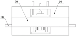
FIG. 2 is a front view of an automated manufacturing line configuration for molding module housings in accordance with the present invention;
FIG. 3 is a schematic view of a partial structure of a forming mold according to the present invention;
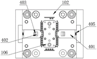
FIG. 4 is a top view of the moving platen and lower die core structure of the present invention;
FIG. 5 is a schematic view of the structure of the fixed die fixing plate, the fixed die plate and the upper die core according to the present invention;
FIG. 6 is a schematic view of the upper die core structure of the present invention;
FIG. 7 is a schematic view of the lower die core structure of the present invention;
FIG. 8 is a side view of the lower core structure of the present invention;
FIG. 9 is a side view of the assembly mechanism structure of the present invention;
fig. 10 is a front view of the structure of the assembly mechanism of the present invention.
In the figure, 10, a forming frame; 20. a carriage; 30. a fixed mount; 40. a material guide pipe of an injection molding machine; 101. a movable mold fixing plate; 102. moving the template; 103. fixing a template; 104. fixing a die fixing plate; 105. a hydraulic cylinder; 106. a lower mold core; 107. an upper mold core; 108. inserting a pin; 109. a groove; 201. a movable plate; 202. a mounting frame; 203. a movable frame; 204. a clamping frame; 205. a movable groove; 206. a first servo electric cylinder; 207. a second servo electric cylinder; 208. a servo motor; 209. a screw; 210. a linear slide rail; 211. a linear motor; 301. a material ejection column; 302. a positioning column; 303. positioning holes; 401. a clamping block; 402. a through hole; 403. a stopper; 404. a fixed block; 405. a spring.
Detailed Description
The technical solutions in the embodiments of the present invention will be clearly and completely described below with reference to the drawings in the embodiments of the present invention, and it is obvious that the described embodiments are only a part of the embodiments of the present invention, and not all of the embodiments. All other embodiments, which can be derived by a person skilled in the art from the embodiments given herein without making any creative effort, shall fall within the protection scope of the present invention.
Example 1:
referring to fig. 1 to 10, an automatic production line for molding a module housing includes a molding frame 10, wherein two sides of the molding frame 10 are respectively provided with a conveying frame 20, the front and the back of the molding frame 10 are respectively provided with a fixing frame 30, a molding mold is arranged inside the molding frame 10, a material guide pipe 40 of an injection molding machine is movably arranged above the molding mold of the molding frame 10, and one side of the two fixing frames 30 opposite to each other is provided with an assembling mechanism;
the forming die comprises a movable die fixing plate 101, fixing legs, a movable die plate 102, a fixed die plate 103 and a fixed die fixing plate 104, a sprue bush is arranged at the top of the fixed die fixing plate 104, two hydraulic oil cylinders 105 are arranged at the top of the movable die fixing plate 101, one ends of driving shafts of the two hydraulic oil cylinders 105 are fixedly connected with the bottom of the movable die plate 102, lower die cores 106 are arranged in the movable die plate 102, at least three lower die cores 106 are arranged, the forming efficiency of a module shell is further improved by circularly replacing the three lower die cores 106, an upper die core 107 matched with the lower die core 106 is arranged in the fixed die plate 103, clamping assemblies are arranged on two sides of the movable die plate 102, and the two clamping assemblies are movably connected with two sides of the lower die core 106;
when the molding die is used for injection molding of the module shell, the lower die core 106 and the upper die core 107 are respectively arranged inside the movable die plate 102 and the fixed die plate 103, then the injection molding material is introduced into the sprue bush at the top of the fixed die fixing plate 104 through the injection molding machine material guide pipe 40, and the molding of the shell is completed between the lower die core 106 and the upper die core 107 by the injection molding material, so that the molding production of the module shell is completed.
The assembling mechanism comprises a movable plate 201, the movable plate 201 is located on one side of the fixed frame 30 and slides horizontally, the front face of the movable plate 201 is movably provided with a mounting frame 202, one side of the mounting frame 202 is provided with a movable frame 203, two sides of the front face of the movable frame 203 are respectively provided with a clamping frame 204 in a sliding manner, four movable grooves 205 are symmetrically formed in two sides of the top and the bottom of the movable frame 203, servo electric cylinders one 206 are respectively arranged inside the four movable grooves 205, the top and the bottom of the two clamping frames 204 are respectively located inside the two movable grooves 205 and are connected in a sliding manner, and one ends of driving shafts of the four servo electric cylinders one 206 are respectively fixedly connected with one sides of the two movable frames 203;
when using assembly devices, at first, the contact pin 108 to the lower mold core 106 both sides is assembled, deliver to assembly devices's below with lower mold core 106 through carriage 20 after that, utilize a servo electric jar 206 drive shaft to drive two holding framves 204 and carry out relative sliding motion, two holding framves 204 contact with the both sides of lower mold core 106 respectively, utilize two holding framves 204 to send into forming die's inside to lower mold core 106 on the carriage 20, need not artifical manual inside of packing into forming die with lower mold core 106, the potential safety hazard in lower mold core 106 assembling process has been avoided, the assembly efficiency to lower mold core 106 has also been improved simultaneously, thereby improve the shaping efficiency to the module shell.
Four servo electric cylinders 207 are symmetrically arranged above and below the inside of the movable plate 201, one ends of driving shafts of the four servo electric cylinders 207 are fixedly connected with one side of the mounting frame 202, a servo motor 208 is arranged below the inside of the mounting frame 202, one end of an output shaft of the servo motor 208 is fixedly connected with a screw rod 209 through a coupler, a connecting block is arranged on the back of the movable frame 203, the inside of the connecting block is in threaded connection with the surface of the screw rod 209, the surface of the connecting block is in sliding connection with the inside of the mounting frame 202, and two sides of the movable frame 203 are respectively in sliding connection with two sides of the inside of the mounting frame 202;
through servo motor 208 output shaft drive screw 209 rotation, because screw 209 and threaded fit between the connecting block are connected, in screw 209 pivoted, the connecting block drives adjustable shelf 203 in one side lapse of mounting bracket 202, it is on same water flat line to descend to the lower mould core 106 at carriage 20 top until adjustable shelf 203, utilize two drive shafts of servo electric jar 207 to promote mounting bracket 202 and be close to lower mould core 106 after that, two holding frame 204 of recycling adjustable shelf 203 one side are fixed lower mould core 106, need not the manual work to carry out the auxiliary operation in the assembling process of lower mould core 106, the improvement is to the assembly efficiency of lower mould core 106 in forming die inside, improve the productivity of module shell, can also reduce the cost of labor consumption simultaneously.
The front of the fixed frame 30 is provided with a linear slide rail 210, the front of the linear slide rail 210 is provided with a linear motor 211, the front of the linear motor 211 is fixedly connected with the back of the movable plate 201, and after the lower mold core 106 is fixedly clamped by the clamping frame 204, the lower mold core 106 is automatically fed into the forming mold by sliding the linear motor 211 on the linear slide rail 210.
Example 2:
according to the invention, a plurality of pins 108 are arranged above two sides of the lower mold core 106, grooves 109 matched with the clamping frames 204 are formed below two sides of the lower mold core 106, the pins 108 are assembled on two sides of the lower mold core 106 in advance, the lower mold core 106 is conveyed into the forming rack 10 through the conveying frame 20, and the two clamping frames 204 enter the two grooves 109, so that the stability of the lower mold core 106 in the process of conveying the lower mold core into the forming mold for assembly is ensured.
Example 3:
according to the invention, the top of the movable mold fixing plate 101 is provided with a material ejection column 301, positioning columns 302 are arranged around the material ejection column 301, the top ends of the four positioning columns 302 extend into the lower mold core 106, positioning holes 303 matched with the positioning columns 302 are formed in the lower mold core 106 and the upper mold core 107, and the four positioning columns 302 are matched with an assembling mechanism to realize quick and accurate assembly of the lower mold core 106 in a forming mold; after the lower mold core 106 is placed in the movable mold plate 102, the movable mold plate 102 is driven to descend by the hydraulic oil cylinder 105, so that the lower mold core 106 and the upper mold core 107 are demolded, then the positioning of the lower mold core 106 in the movable mold plate 102 by the clamping component is released, the movable mold plate 102 continues to descend, the lower mold core 106 is ejected out of the movable mold plate 102 by the ejection column 301, the lower mold core 106 is sent out of the integral forming mold by the assembling mechanism on the right side of the fixing frame 30, then the lower mold core 106 assembled by the contact pins 108 is sent into the forming mold by the assembling mechanism on the left side of the fixing frame 30 for assembling, and the productivity of a mold shell is effectively improved by quickly replacing the lower mold core 106 in the forming mold.
The guide posts are arranged on the periphery of the top of the movable mold fixing plate 101, the top of the movable mold fixing plate 101 is fixedly connected with the bottoms of the fixing legs, the top ends of the four guide posts are connected with the periphery of the inside of the movable mold plate 102 in a sliding mode, the movable mold plate 102 is located under the fixed mold plate 103, and the bottom of the fixed mold fixing plate 104 of the fixed mold plate 103 is fixedly connected.
Example 4:
the clamping assembly comprises clamping blocks 401, the clamping blocks 401 are movably arranged on two sides inside a movable template 102, through holes 402 are formed in the two clamping blocks 401, a stop block 403 is movably arranged inside the through hole 402, the stop block 403 electrically drives the through hole 402 to slide left and right, fixed blocks 404 are arranged on two sides of the movable template 102, springs 405 are arranged on one sides of the two fixed blocks 404, one ends of the two springs 405 are fixedly connected with one sides of the clamping blocks 401 respectively, and one sides of the two clamping blocks 401 extend into grooves 109 on two sides of a lower mold core 106 respectively;
after the molding of the module shell is completed, the hydraulic oil cylinder 105 drives the movable template 102 to descend, so that the lower mold core 106 and the upper mold core 107 are demolded, then the two stoppers 403 respectively slide to one side of the two fixed blocks 404, one side of each of the two stoppers 401 is separated from the two grooves 109, so that the positioning of the clamping component on the lower mold core 106 in the movable template 102 is released, the movable template 102 continues to descend, the material ejecting column 301 ejects the lower mold core 106 from the movable template 102, the lower mold core 106 is automatically sent out in the movable template 102, then the lower mold core 106 with the molded module shell is sent out by matching with an assembling mechanism, and the automatic molding production of the module shell is completed.
Example 5:
referring to fig. 1-10, the present invention further discloses a production method of an automatic production line for molding a module housing, which specifically includes the following steps:
firstly, pins 108 on two sides of a lower mold core 106 are assembled, and then the lower mold core 106 is conveyed into the forming rack 10 through a conveying frame 20 on the left side;
secondly, the output shaft of the servo motor 208 drives the screw 209 to rotate, and due to the thread fit connection between the screw 209 and the connecting block, when the screw 209 rotates, the connecting block drives the movable frame 203 to slide downwards on one side of the mounting frame 202 until the movable frame 203 descends to be on the same horizontal line with the lower mold core 106 at the top of the conveying frame 20, then the driving shaft of the servo electric cylinder II 207 is used for pushing the mounting frame 202 to be close to the lower mold core 106, the driving shaft of the servo electric cylinder I206 drives the two clamping frames 204 to perform relative sliding movement, and one sides of the two clamping frames 204 respectively enter the grooves 109 at two sides of the lower mold core 106;
thirdly, the hydraulic oil cylinder 105 drives the movable template 102 to descend, the linear motor 211 slides on the linear slide rail 210 to automatically send the lower mold core 106 into the forming mold, then the movable frame 203 descends to enable the positioning hole 303 in the lower mold core 106 to be matched and connected with the four positioning columns 302, at the moment, the two clamping frames 204 are separated from the two grooves 109, and the lower mold core 106 is assembled in the forming mold;
fourthly, the lower mold core 106 and the upper mold core 107 are closed, injection molding materials are introduced into a sprue bush at the top of the fixed mold fixing plate 104 through the material guide pipe 40 of the injection molding machine, and the injection molding materials complete the molding of the shell between the lower mold core 106 and the upper mold core 107;
fifthly, the hydraulic oil cylinder 105 drives the movable mould plate 102 to descend, so that the lower mould core 106 and the upper mould core 107 are demoulded, then the two stop blocks 403 respectively slide to one sides of the two fixed blocks 404, one sides of the two stop blocks 401 are respectively separated from the two grooves 109, so that the positioning of the lower mould core 106 in the movable mould plate 102 by the clamping components is released, the movable mould plate 102 continues to descend, the lower mould core 106 is ejected out of the movable mould plate 102 by the ejection columns 301, the lower mould core 106 is sent out of the integral forming mould by matching with the assembling mechanism on the right side of the fixed frame 30, then the lower mould core 106 assembled by the contact pins 108 is sent into the forming mould by the assembling mechanism on the left side of the fixed frame 30 for assembling, the quick replacement of the lower mould core 106 in the forming mould is completed, and the forming production of the module shell is continued.
And those not described in detail in this specification are well within the skill of those in the art.
It should be noted that, in this document, relational terms such as first and second, and the like are used solely to distinguish one entity or action from another entity or action without necessarily requiring or implying any actual such relationship or order between such entities or actions. Also, the terms "comprises," "comprising," or any other variation thereof, are intended to cover a non-exclusive inclusion, such that a process, method, article, or apparatus that comprises a list of elements does not include only those elements but may include other elements not expressly listed or inherent to such process, method, article, or apparatus.
Although embodiments of the present invention have been shown and described, it will be appreciated by those skilled in the art that changes, modifications, substitutions and alterations can be made in these embodiments without departing from the principles and spirit of the invention, the scope of which is defined in the appended claims and their equivalents.
Claims (5)
1. The utility model provides a be used for fashioned automatic production line of module shell, includes forming frame (10), the both sides of forming frame (10) all are provided with carriage (20), and the front of forming frame (10) all is provided with mount (30), its characterized in that with the back: a forming die is arranged in the forming rack (10), a material guide pipe (40) of the injection molding machine is movably arranged above the forming die of the forming rack (10), and assembling mechanisms are arranged on the opposite sides of the two fixing frames (30);
the forming die comprises a movable die fixing plate (101), fixing feet, a movable die plate (102), a fixed die plate (103) and a fixed die fixing plate (104), a sprue bush is arranged at the top of the fixed die fixing plate (104), two hydraulic oil cylinders (105) are arranged at the top of the movable die fixing plate (101), one ends of driving shafts of the two hydraulic oil cylinders (105) are fixedly connected with the bottom of the movable die plate (102), a lower die core (106) is arranged inside the movable die plate (102), an upper die core (107) matched with the lower die core (106) is arranged inside the fixed die plate (103), clamping components are arranged on two sides of the movable die plate (102), and the two clamping components are movably connected with two sides of the lower die core (106);
the assembling mechanism comprises a movable plate (201), the movable plate (201) is located on one side of a fixed frame (30) and slides horizontally, a mounting frame (202) is movably arranged on the front face of the movable plate (201), a movable frame (203) is arranged on one side of the mounting frame (202), clamping frames (204) are arranged on two sides of the front face of the movable frame (203) in a sliding mode, four movable grooves (205) are symmetrically formed in two sides of the top and the bottom of the movable frame (203), servo electric cylinders I (206) are arranged inside the four movable grooves (205), the top and the bottom of the two clamping frames (204) are respectively located in the two movable grooves (205) and are in sliding connection, and one ends of driving shafts of the four servo electric cylinders I (206) are respectively fixedly connected with one side of the two movable frames (203);
four servo electric cylinders II (207) are symmetrically arranged above and below the inside of the movable plate (201), one ends of driving shafts of the four servo electric cylinders II (207) are fixedly connected with one side of the mounting frame (202), a servo motor (208) is arranged below the inside of the mounting frame (202), one end of an output shaft of the servo motor (208) is fixedly connected with a screw rod (209) through a coupler, a connecting block is arranged on the back of the movable frame (203), the inside of the connecting block is in threaded connection with the surface of the screw rod (209), the surface of the connecting block is in sliding connection with the inside of the mounting frame (202), and two sides of the movable frame (203) are respectively in sliding connection with two sides of the inside of the mounting frame (202);
a plurality of contact pins (108) are arranged above two sides of the lower mold core (106), and grooves (109) matched with the clamping frame (204) are formed below two sides of the lower mold core (106);
the top of movable mould fixed plate (101) is provided with ejection post (301), and is located all around of ejection post (301) and all is provided with reference column (302), four the top of reference column (302) all extends to the inside of lower mold core (106), and all offer around with reference column (302) matched with locating hole (303) down mold core (106) and last mold core (107) inside.
2. An automated production line for the moulding of module housings, according to claim 1, characterized in that: the front of the fixed frame (30) is provided with a linear sliding rail (210), the front of the linear sliding rail (210) is provided with a linear motor (211), and the front of the linear motor (211) is fixedly connected with the back of the movable plate (201).
3. An automated production line for the moulding of module housings, according to claim 1, characterized in that: the die comprises a fixed die plate (103), a movable die fixing plate (101), guide columns, a fixed pin, a movable die fixing plate (102), a fixed die fixing plate (104), a fixed die fixing plate (103), a movable die fixing plate (101), a movable die fixing plate (102) and a movable die fixing plate (101).
4. An automated production line for the moulding of module housings, according to claim 1, characterized in that: the screens subassembly includes fixture block (401), fixture block (401) is all movably provided with in the inside both sides of movable mould board (102), and through-hole (402) have all been seted up to the inside of two fixture blocks (401), the inside activity of through-hole (402) is provided with dog (403), and dog (403) pass through the electric drive and slide about the inside of through-hole (402), the both sides of movable mould board (102) all are provided with fixed block (404), and one side of two fixed blocks (404) all is provided with spring (405), two the one end of spring (405) respectively with one side fixed connection of fixture block (401), and one side of two fixture blocks (401) extends respectively to in recess (109) of lower mold core (106) both sides.
5. A production method of an automatic production line for molding a module shell is characterized in that: the method specifically comprises the following steps:
firstly, pins (108) on two sides of a lower mold core (106) are assembled, and then the lower mold core (106) is conveyed into a forming rack (10) through a conveying rack (20) on the left side;
secondly, an output shaft of a servo motor (208) drives a screw rod (209) to rotate, and due to the fact that the screw rod (209) is in threaded fit connection with a connecting block, the connecting block drives a movable frame (203) to slide downwards on one side of a mounting frame (202) when the screw rod (209) rotates until the movable frame (203) descends to be on the same horizontal line with a lower mold core (106) at the top of a conveying frame (20), then a driving shaft of a servo electric cylinder II (207) is used for pushing the mounting frame (202) to be close to the lower mold core (106), a driving shaft of a servo electric cylinder I (206) drives two clamping frames (204) to perform relative sliding movement, and one sides of the two clamping frames (204) respectively enter grooves (109) on two sides of the lower mold core (106);
thirdly, the hydraulic oil cylinder (105) drives the movable template (102) to descend, the linear motor (211) slides on the linear slide rail (210), the lower mold core (106) is automatically sent into the forming mold, then the movable frame (203) descends, the positioning hole (303) in the lower mold core (106) is matched and connected with the four positioning columns (302), at the moment, the two clamping frames (204) are separated from the two grooves (109), and the lower mold core (106) is assembled in the forming mold;
fourthly, the lower mold core (106) and the upper mold core (107) are closed, injection molding materials are introduced into a sprue bush at the top of the fixed mold fixing plate (104) through a material guide pipe (40) of the injection molding machine, and the injection molding materials complete the molding of the shell between the lower mold core (106) and the upper mold core (107);
fifthly, the hydraulic oil cylinder (105) drives the movable mould plate (102) to descend to demould the lower mould core (106) and the upper mould core (107), then the two stoppers (403) respectively slide towards one side of the two fixing blocks (404) to ensure that one side of the two clamping blocks (401) respectively separate from the two grooves (109), thereby releasing the positioning of the clamping component on the lower mold core (106) in the movable mold plate (102), the movable mold plate (102) continuously descends, the material ejection column (301) ejects the lower mold core (106) out of the movable mold plate (102), the lower mold core (106) is sent out from the integral forming mold by matching with the assembly mechanism at the right side of the fixed frame (30), and then the lower mold core (106) assembled by the pins (108) is sent into a forming mold for assembly by an assembling mechanism on the left side of the fixed frame (30), so that the lower mold core (106) is rapidly replaced in the forming mold, and the forming production of the module shell is continued.
Priority Applications (1)
| Application Number | Priority Date | Filing Date | Title |
|---|---|---|---|
| CN202111171738.0A CN113815182B (en) | 2021-10-08 | 2021-10-08 | Automatic production line for molding module shell and production method thereof |
Applications Claiming Priority (1)
| Application Number | Priority Date | Filing Date | Title |
|---|---|---|---|
| CN202111171738.0A CN113815182B (en) | 2021-10-08 | 2021-10-08 | Automatic production line for molding module shell and production method thereof |
Publications (2)
| Publication Number | Publication Date |
|---|---|
| CN113815182A CN113815182A (en) | 2021-12-21 |
| CN113815182B true CN113815182B (en) | 2022-06-07 |
Family
ID=78916212
Family Applications (1)
| Application Number | Title | Priority Date | Filing Date |
|---|---|---|---|
| CN202111171738.0A Active CN113815182B (en) | 2021-10-08 | 2021-10-08 | Automatic production line for molding module shell and production method thereof |
Country Status (1)
| Country | Link |
|---|---|
| CN (1) | CN113815182B (en) |
Family Cites Families (5)
| Publication number | Priority date | Publication date | Assignee | Title |
|---|---|---|---|---|
| CN103878905B (en) * | 2014-04-09 | 2016-04-27 | 威猛工业自动化系统(昆山)有限公司 | Inlay iron plate automatic charging device and control method thereof |
| CN204685834U (en) * | 2015-05-13 | 2015-10-07 | 成都市和乐门业有限公司 | A kind of mould of fast changeable core rod |
| CN107225791B (en) * | 2017-06-29 | 2023-05-16 | 扬力集团股份有限公司 | Quick die change device |
| CN107415166B (en) * | 2017-09-05 | 2023-09-19 | 温州瑞都特殊钢有限公司 | Die carrier convenient to change mould benevolence |
| CN109624201B (en) * | 2019-01-19 | 2024-07-16 | 广东速博智能科技有限公司 | Automatic iron sheet feeding secondary taking out and embedding production system |
-
2021
- 2021-10-08 CN CN202111171738.0A patent/CN113815182B/en active Active
Also Published As
| Publication number | Publication date |
|---|---|
| CN113815182A (en) | 2021-12-21 |
Similar Documents
| Publication | Publication Date | Title |
|---|---|---|
| CN206106278U (en) | Ejection mechanism and injection mold | |
| CN211591158U (en) | Internal core-pulling injection mold with adjustable core-pulling distance | |
| CN210758877U (en) | Inlaid automatic material-pulling plastic mould | |
| CN106064445A (en) | A kind of material conveyor and use the injection machine of this device | |
| CN113815182B (en) | Automatic production line for molding module shell and production method thereof | |
| CN213860485U (en) | Injection mold of printer main support | |
| CN2759758Y (en) | Two-stage side-wise loose-core device of plastic mould | |
| CN210047127U (en) | Heavy tablet press | |
| CN108481660B (en) | Double-layer mold opening device and rubber injection machine with same | |
| CN214111295U (en) | Plastic mould with double limiting structure | |
| CN215879773U (en) | Novel core shooter | |
| CN106903865B (en) | Automatic production equipment of hot water bags and production method of hot water bags | |
| CN205871022U (en) | Material transport device and use device's injection molding machine | |
| CN211054271U (en) | Precision electric connector mould | |
| CN210651688U (en) | Mould for forming CD sound button cap with one outlet and multiple outlets | |
| CN211164996U (en) | Automatic bearing roller placing mechanism for injection mold | |
| CN111941755A (en) | Injection molding for rotor assembly of direct-current brushless motor and injection molding method thereof | |
| CN220903997U (en) | Injection mold of conveyer plastic chain plate | |
| CN220219494U (en) | Quick-change die for injection molding of multi-pin terminal | |
| CN216230584U (en) | Injection mold convenient to take off material | |
| CN217293247U (en) | Mould is used in switching power supply shell production convenient to get material | |
| CN221809560U (en) | Mold positioning device for injection mold | |
| CN212422021U (en) | Injection mold with lining fixing frame | |
| CN220923174U (en) | Screw injection mold | |
| CN220146564U (en) | Injection mold with accurate positioning |
Legal Events
| Date | Code | Title | Description |
|---|---|---|---|
| PB01 | Publication | ||
| PB01 | Publication | ||
| SE01 | Entry into force of request for substantive examination | ||
| SE01 | Entry into force of request for substantive examination | ||
| GR01 | Patent grant | ||
| GR01 | Patent grant |