CN113776601A - Temperature and pressure flow monitoring device for environmental protection on-line monitoring - Google Patents
Temperature and pressure flow monitoring device for environmental protection on-line monitoring Download PDFInfo
- Publication number
- CN113776601A CN113776601A CN202111172702.4A CN202111172702A CN113776601A CN 113776601 A CN113776601 A CN 113776601A CN 202111172702 A CN202111172702 A CN 202111172702A CN 113776601 A CN113776601 A CN 113776601A
- Authority
- CN
- China
- Prior art keywords
- pressure flow
- pitot tube
- fixing
- flow monitoring
- warm
- Prior art date
- Legal status (The legal status is an assumption and is not a legal conclusion. Google has not performed a legal analysis and makes no representation as to the accuracy of the status listed.)
- Granted
Links
- 238000012806 monitoring device Methods 0.000 title claims abstract description 82
- 238000012544 monitoring process Methods 0.000 title claims abstract description 21
- 230000007613 environmental effect Effects 0.000 title claims description 15
- 239000000428 dust Substances 0.000 claims abstract description 26
- 239000007787 solid Substances 0.000 claims abstract description 11
- 230000002457 bidirectional effect Effects 0.000 claims description 29
- 230000002093 peripheral effect Effects 0.000 claims description 17
- 238000009423 ventilation Methods 0.000 claims description 4
- 239000010985 leather Substances 0.000 claims 1
- 239000007858 starting material Substances 0.000 abstract description 3
- 241000883990 Flabellum Species 0.000 abstract description 2
- 238000000926 separation method Methods 0.000 abstract description 2
- 239000000779 smoke Substances 0.000 description 22
- 230000000694 effects Effects 0.000 description 7
- 230000000391 smoking effect Effects 0.000 description 5
- 238000007664 blowing Methods 0.000 description 3
- 238000004140 cleaning Methods 0.000 description 3
- 238000003780 insertion Methods 0.000 description 3
- 230000037431 insertion Effects 0.000 description 3
- UGFAIRIUMAVXCW-UHFFFAOYSA-N Carbon monoxide Chemical compound [O+]#[C-] UGFAIRIUMAVXCW-UHFFFAOYSA-N 0.000 description 2
- 238000001514 detection method Methods 0.000 description 2
- 239000003546 flue gas Substances 0.000 description 2
- 238000003825 pressing Methods 0.000 description 2
- 230000009286 beneficial effect Effects 0.000 description 1
- 238000005260 corrosion Methods 0.000 description 1
- 238000005516 engineering process Methods 0.000 description 1
- 238000011010 flushing procedure Methods 0.000 description 1
- 238000004519 manufacturing process Methods 0.000 description 1
- 238000005259 measurement Methods 0.000 description 1
- 230000002035 prolonged effect Effects 0.000 description 1
- 238000009987 spinning Methods 0.000 description 1
- 230000003068 static effect Effects 0.000 description 1
- 238000005406 washing Methods 0.000 description 1
Images


Classifications
-
- G—PHYSICS
- G01—MEASURING; TESTING
- G01D—MEASURING NOT SPECIALLY ADAPTED FOR A SPECIFIC VARIABLE; ARRANGEMENTS FOR MEASURING TWO OR MORE VARIABLES NOT COVERED IN A SINGLE OTHER SUBCLASS; TARIFF METERING APPARATUS; MEASURING OR TESTING NOT OTHERWISE PROVIDED FOR
- G01D21/00—Measuring or testing not otherwise provided for
- G01D21/02—Measuring two or more variables by means not covered by a single other subclass
-
- B—PERFORMING OPERATIONS; TRANSPORTING
- B08—CLEANING
- B08B—CLEANING IN GENERAL; PREVENTION OF FOULING IN GENERAL
- B08B17/00—Methods preventing fouling
- B08B17/02—Preventing deposition of fouling or of dust
-
- B—PERFORMING OPERATIONS; TRANSPORTING
- B08—CLEANING
- B08B—CLEANING IN GENERAL; PREVENTION OF FOULING IN GENERAL
- B08B9/00—Cleaning hollow articles by methods or apparatus specially adapted thereto
- B08B9/08—Cleaning containers, e.g. tanks
- B08B9/0804—Cleaning containers having tubular shape, e.g. casks, barrels, drums
- B08B9/0808—Cleaning containers having tubular shape, e.g. casks, barrels, drums by methods involving the use of tools, e.g. by brushes, scrapers
-
- B—PERFORMING OPERATIONS; TRANSPORTING
- B08—CLEANING
- B08B—CLEANING IN GENERAL; PREVENTION OF FOULING IN GENERAL
- B08B9/00—Cleaning hollow articles by methods or apparatus specially adapted thereto
- B08B9/08—Cleaning containers, e.g. tanks
- B08B9/0804—Cleaning containers having tubular shape, e.g. casks, barrels, drums
- B08B9/0813—Cleaning containers having tubular shape, e.g. casks, barrels, drums by the force of jets or sprays
-
- G—PHYSICS
- G01—MEASURING; TESTING
- G01D—MEASURING NOT SPECIALLY ADAPTED FOR A SPECIFIC VARIABLE; ARRANGEMENTS FOR MEASURING TWO OR MORE VARIABLES NOT COVERED IN A SINGLE OTHER SUBCLASS; TARIFF METERING APPARATUS; MEASURING OR TESTING NOT OTHERWISE PROVIDED FOR
- G01D11/00—Component parts of measuring arrangements not specially adapted for a specific variable
Landscapes
- Physics & Mathematics (AREA)
- General Physics & Mathematics (AREA)
- Engineering & Computer Science (AREA)
- Mechanical Engineering (AREA)
- Measuring Volume Flow (AREA)
- Structures Of Non-Positive Displacement Pumps (AREA)
Abstract
The invention discloses a temperature and pressure flow monitoring device for environment-friendly online monitoring, which belongs to the technical field of environment monitoring equipment and comprises a temperature and pressure flow monitoring device main body, wherein a pitot tube is arranged on the side surface of the temperature and pressure flow monitoring device main body, the pitot tube is arranged on the temperature and pressure flow monitoring device main body through a pitot tube fixing ring, a fixing block is arranged on the inner wall of the pitot tube, a fixing belt is fixedly connected to the side surface of the fixing block, which is far away from the inner wall of the pitot tube, and a motor fixing box is fixedly connected to the side surface of the fixing belt; when the staff is clearing up the dust to the pitot tube, the staff is through holding the connecting rod tightly, then revolve to twist the connecting rod and make the screw ring twist out from the pitot tube is internal, then the staff revolves the barrel soon, the solid fixed ring of second that makes the barrel centre of a circle department revolves the outside of revolving the axle soon, and through revolving first solid fixed ring and flabellum and pivot separation soon, then starter motor, the motor can drive barrel and scraper blade and rotate, thereby can clear up the inner wall of pitot tube, make things convenient for the staff to use.
Description
Technical Field
The invention relates to the technical field of environment monitoring equipment, in particular to a temperature and pressure flow monitoring device for environment-friendly online monitoring.
Background
As the environmental protection concept is accepted by more and more people, the concept of sustainable development is also proposed by the nation, and relevant policy and regulation are provided. Wherein the smoke emission aiming at the production enterprises is also important. The temperature and pressure integrated monitor (hereinafter referred to as temperature and pressure monitor) is composed of an S-shaped pitot tube, a thermal resistor, a micro differential pressure/absolute pressure sensor group, a back flushing unit, a signal control processor and the like, is an integrated flow rate, dynamic pressure, static pressure and smoke temperature monitor developed specially for high-dust, high-temperature, high-humidity and high-corrosion environments for smoke emission monitoring, meets the requirements of national relevant standards, and is suitable for a continuous smoke emission monitoring system (CEMS) to perform real-time continuous measurement on the flow rate, pressure, temperature and flow of smoke.
But the warm-pressing current monitoring devices who is used for environmental protection on-line monitoring exist and use for a long time and lead to the more dust that leads to in the pitot tube to inconvenient staff's clearance and motor damage back warm-pressing current monitoring devices can not normally work the problem.
Disclosure of Invention
The invention aims to provide a temperature and pressure flow monitoring device for environment-friendly online monitoring, so as to solve the problems in the background technology.
In order to achieve the purpose, the invention provides the following technical scheme:
a temperature and pressure flow monitoring device for environmental protection online monitoring comprises a temperature and pressure flow monitoring device main body, wherein a pitot tube is arranged on the side surface of the temperature and pressure flow monitoring device main body, the pitot tube is arranged on the temperature and pressure flow monitoring device main body through a pitot tube fixing ring, a fixing block is arranged on the inner wall of the pitot tube, a fixing band is fixedly connected to the side surface of the fixing block away from the inner wall of the pitot tube, a motor fixing box is fixedly connected to the side surface of the fixing band, a fixing frame for fixing a motor is fixedly connected to the inside of the motor fixing box, a motor is arranged on the fixing frame, a rotating shaft is fixedly connected to the output end of the motor, a first fixing ring is arranged at the end part of the rotating shaft away from the motor, fan blades are fixedly connected to the outer peripheral surface of the first fixing ring, and a second fixing ring is in threaded connection between the motor and the first fixing ring, fixedly connected with barrel on the solid fixed ring's of second outer peripheral face, be provided with the scraper blade on the surface of barrel, the inside of pitot tube one end is seted up threadedly, the internal thread connection of pitot tube has the screw ring, the internal fixedly connected with gauze of screw ring, be provided with the solenoid valve on the solid fixed ring's of second outer peripheral face, when the staff cleared up the dust in the pitot tube, the staff revolves the connecting rod through holding tightly, then revolves to twist the connecting rod and makes the screw ring screw out from the pitot tube is internal-spinning, then the staff twists the barrel soon, makes the solid fixed ring of second of barrel centre of a circle department twist to the outside of pivot, and through revolving first solid fixed ring and flabellum separation soon, then the starter motor can drive barrel and scraper blade and rotate to can clear up the inner wall of pitot tube, make things convenient for the staff to use, through setting up motor, When the device is used, the motor can drive the rotating shaft, the first fixing ring and the fan blade to rotate by starting the motor, so that smoke can be sucked into the pitot tube, then the smoke enters the body of the temperature and pressure flow monitoring device through the pitot tube to be detected, the aim of detecting the discharged smoke in real time is fulfilled by continuous suction, after long-time operation, the normal work of the body of the temperature and pressure flow monitoring device can be ensured even if one of the smoking devices is damaged by replacing different smoking devices due to the fact that the electromagnetic valve is closed, and the normal work of the body of the temperature and pressure flow monitoring device can be ensured by changing the working time of the two-way fan and the motor, the alternating operation can further improve the service life of the bidirectional fan and the motor.
As a further scheme of the invention: the rectangular channel has been seted up to the outer peripheral face of pitot tube, the inside of rectangular channel is provided with two-way fan, the fixed frame that the surface fixedly connected with of two-way fan is used for fixing two-way fan on the pitot tube, through setting up two-way fan, fixed frame, the screw, the connection frame, rectangular frame and ventilation hole, open two-way fan in the starter motor, two-way fan can blow off the dust that barrel and scraper blade clearance got off outside the pitot tube, avoid the dust to enter into the inside of warm pressure stream monitoring devices main part, and then play the effect of warm pressure stream monitoring devices main part protection, through setting up threaded ring and gauze, the setting of gauze can reduce the dust and enter into in the pitot tube, play the effect that the dust enters into warm pressure stream monitoring devices, and be convenient for washing and dismantlement, make things convenient for the staff to use.
As a still further scheme of the invention: the fixing frame is characterized in that a bolt insertion hole is formed in the side face of the fixing frame, a screw used for fixing the fixing frame on the outer peripheral face of the pitot tube is connected to the thread insertion hole in an internal thread mode, and the screw and the thread insertion hole play a role in connecting the fixing frame with the pitot tube.
As a still further scheme of the invention: through stationary blade fixedly connected with connecting block on the upper surface of warm pressure flow monitoring devices main part, the quantity of connecting block is two, two the connecting block sets up for the interval, be provided with the link on the connecting block side up, the setting of connecting block and link plays the effect that makes things convenient for the staff to carry and take this device.
As a still further scheme of the invention: the utility model discloses a monitoring device, including the warm pressure stream monitoring device main part, the lower fixed surface who flows the monitoring device main part is pressed to warm pressure, the bracing piece is connected with the bracing piece, one side fixedly connected with supporting seat that the warm pressure stream monitoring device main part was kept away from to the bracing piece, the quantity of bracing piece is four, four the bracing piece is in the left and right sides of warm pressure stream monitoring device main part lower surface with rectangular array's form fixed connection, and the bracing piece plays and supports and fixed effect the warm pressure stream monitoring device main part.
As a still further scheme of the invention: one side fixedly connected with circular sheet of screw thread ring, be provided with two horizontal poles, two about the ring center symmetry of screw thread ring on the side of circular sheet the connecting rod has been linked firmly between the horizontal pole, and the setting of horizontal pole and connecting rod plays the effect of conveniently revolving soon the screw thread ring.
As a still further scheme of the invention: the bidirectional fan is characterized in that a connecting frame and a rectangular frame are sequentially arranged on the outward side face of the bidirectional fan, a plurality of ventilation holes are uniformly distributed in the side face of the rectangular frame at intervals, and the rectangular frame and the connecting frame play a role in protecting the bidirectional fan.
As a still further scheme of the invention: one side of warm pressure flow monitoring devices main part is provided with the warning light, be provided with the fixed plate through the bolt on the side of warm pressure flow monitoring devices main part, transversely extend on the side of fixed plate and seted up the radiating groove, the inside of radiating groove is provided with magnet, one side of magnet is provided with the dust screen, and the setting of dust screen and radiating groove plays radiating effect, promotes inside and outside circulation of air.
As a still further scheme of the invention: one side of warm pressure stream monitoring devices main part (1) is provided with display screen (35).
Compared with the prior art, the invention has the beneficial effects that:
1. according to the invention, by arranging the pitot tube, the fixing block, the fixing belt, the motor fixing box, the fixing frame, the motor, the rotating shaft, the first fixing ring, the fan blade, the second fixing ring, the barrel body and the scraper blade, when a worker cleans dust in the pitot tube, the worker tightly holds the connecting rod, then twists the connecting rod to enable the threaded ring to be screwed out of the pitot tube, then twists the barrel body by the worker, so that the second fixing ring at the center of the barrel body is twisted to the outside of the rotating shaft, and is separated from the rotating shaft by twisting the first fixing ring and the fan blade, then the motor is started, and the motor can drive the barrel body and the scraper blade to rotate, so that the inner wall of the pitot tube can be cleaned, and the use of the worker is facilitated.
2. According to the invention, the bidirectional fan is started while the motor is started through the bidirectional fan, the fixing frame, the screws, the connecting frame, the rectangular frame and the ventilation holes, the bidirectional fan can blow out dust cleaned by the barrel and the scraper to the outside of the pitot tube, the dust is prevented from entering the inside of the body of the temperature and pressure flow monitoring device, and the body of the temperature and pressure flow monitoring device is protected.
3. In the invention, by arranging the motor, the rotating shaft, the first fixing ring and the fan blade, when in use, the motor can drive the rotating shaft, the first fixing ring and the fan blade to rotate by starting the motor, so that smoke can be sucked into the pitot tube, then the smoke enters the body of the temperature and pressure flow monitoring device through the pitot tube to be detected, and the aim of detecting the discharged smoke in real time is fulfilled by continuous suction, after long-time operation, the smoke can be sucked into the body of the temperature and pressure flow monitoring device along the pitot tube by closing the electromagnetic valve and the motor and then adjusting the blowing direction of the bidirectional fan, and the smoke enters the body of the temperature and pressure flow monitoring device by closing the electromagnetic valve, so that the device can ensure the normal work of the body of the temperature and pressure flow monitoring device even if one of the smoke suction devices is damaged, and can ensure the normal work time of the temperature and pressure flow monitoring device through the bidirectional fan and the motor, the alternating operation can further improve the service life of the bidirectional fan and the motor.
Drawings
FIG. 1 is a schematic structural view of the present invention;
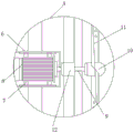
FIG. 2 is a schematic cross-sectional view of a pitot tube according to the present invention;
FIG. 3 is an enlarged view of the structure at A in FIG. 2 according to the present invention;
FIG. 4 is a schematic structural view of a bidirectional blower of the present invention;
FIG. 5 is a schematic structural view of a bi-directional blower of the present invention;
fig. 6 is a schematic structural view of the cartridge in the present invention.
In the figure: 1. a temperature pressure flow monitoring device main body; 2. a pitot tube fixing ring; 3. a pitot tube; 4. a fixed block; 5. fixing belts; 6. a motor fixing box; 7. a fixed mount; 8. a motor; 9. a rotating shaft; 10. a first retaining ring; 11. a fan blade; 12. a second retaining ring; 13. a barrel; 14. a squeegee; 15. a threaded ring; 16. a screen; 17. a bidirectional fan; 18. a fixing frame; 19. a screw; 20. a fixing sheet; 21. connecting blocks; 22. hanging a ring; 23. a support bar; 24. a supporting seat; 25. a cross bar; 26. a connecting rod; 27. a connecting frame; 28. a rectangular frame; 29. a vent hole; 30. an alarm light; 31. a bolt; 32. a fixing plate; 33. a heat sink; 34. a dust screen; 35. a display screen.
Detailed Description
The technical solutions in the embodiments of the present invention will be clearly and completely described below with reference to the drawings in the embodiments of the present invention, and it is obvious that the described embodiments are only a part of the embodiments of the present invention, and not all of the embodiments. All other embodiments, which can be derived by a person skilled in the art from the embodiments given herein without making any creative effort, shall fall within the protection scope of the present invention.
Referring to fig. 1 to 6, in the embodiment of the present invention, the warm and pressure flow monitoring device for environmental protection online monitoring includes a warm and pressure flow monitoring device main body 1, a pitot tube 3 is disposed on a side surface of the warm and pressure flow monitoring device main body, the pitot tube 3 is disposed on the warm and pressure flow monitoring device main body through a pitot tube fixing ring 2, a fixing block 4 is disposed on an inner wall of the pitot tube 3, a fixing band 5 is fixedly connected to a side surface of the fixing block 4 away from the inner wall of the pitot tube 3, a motor fixing box 6 is fixedly connected to a side surface of the fixing band 5, a fixing frame 7 for fixing a motor 8 is fixedly connected to an inside of the motor fixing box 6, the fixing frame 7 is provided with a motor 8, an output end of the motor 8 is fixedly connected to a rotating shaft 9, a first fixing ring 10 is disposed on an end portion of the rotating shaft 9 away from the motor 8, when a worker cleans dust in the pitot tube 3, the worker tightly holds a connecting rod 26, then the connecting rod 26 is screwed to enable the threaded ring 15 to be screwed out of the pitot tube 3, then a worker screws the cylinder body 13 to enable the second fixing ring 12 at the circle center of the cylinder body 13 to be screwed to the outer part of the rotating shaft 9, the first fixing ring 10 and the fan blade 11 are screwed to be separated from the rotating shaft 9, then the motor 8 is started, the motor 8 can drive the cylinder body 13 and the scraper 14 to rotate, so that the inner wall of the pitot tube 3 can be cleaned, the use of the pitot tube is facilitated, the fan blade 11 is fixedly connected to the outer peripheral surface of the first fixing ring 10, the second fixing ring 12 is in threaded connection between the motor 8 and the first fixing ring 10 on the outer peripheral surface of the rotating shaft 9, the first fixing ring 10 and the fan blade 11 are arranged, when the pitot tube is used, the motor 8 can drive the rotating shaft 9, the first fixing ring 10 and the fan blade 11 to rotate by starting the motor 8, and then smoke can be sucked into the pitot tube 3, then the smoke enters the main body 1 of the temperature and pressure flow monitoring device through the pitot tube 3 for detection, the aim of detecting the discharged smoke in real time is achieved through continuous suction, after the smoke runs for a long time, the electromagnetic valve and the motor 8 are closed, then the blowing direction of the bidirectional fan 17 is adjusted, the smoke can be sucked into the pitot tube 3, and at the moment, the smoke enters the main body 1 of the temperature and pressure flow monitoring device along the pitot tube 3 due to the closing of the electromagnetic valve, so that the normal work of the main body 1 of the temperature and pressure flow monitoring device can be ensured even if one of the two smoking devices is damaged through replacing different smoking devices, the normal work of the main body 1 of the temperature and pressure flow monitoring device can be ensured through the working time of the bidirectional fan 17 and the motor 8, the service lives of the bidirectional fan 17 and the motor 8 can be prolonged, a cylinder body 13 is fixedly connected on the peripheral surface of the second fixing ring 12, and a scraper 14 is arranged on the outer surface of the cylinder body 13, the inside of 3 one ends of pitot tube is seted up threadedly, and the inside threaded connection of pitot tube 3 has screw ring 15, and the inside fixedly connected with gauze 16 of screw ring 15 is provided with the solenoid valve on the outer peripheral face of second solid fixed ring 12.
Wherein, a rectangular groove is arranged on the outer peripheral surface of the pitot tube 3, a bidirectional fan 17 is arranged in the rectangular groove, a fixing frame 18 for fixing the bidirectional fan 17 on the pitot tube 3 is fixedly connected to the outer surface of the bidirectional fan 17, the bidirectional fan 17 is opened when the motor 8 is started by arranging the bidirectional fan 17, the fixing frame 18, a screw 19, a connecting frame 27, a rectangular frame 28 and a vent hole 29, the bidirectional fan 17 can blow out dust cleaned by the barrel 13 and the scraper 14 to the outside of the pitot tube 3, the dust is prevented from entering the inside of the temperature and pressure flow monitoring device main body 1, and the temperature and pressure flow monitoring device main body 1 is protected by the bidirectional fan 17, the dust can be reduced from entering the pitot tube 3 by arranging the threaded ring 15 and the gauze 16, the gauze 16 is prevented from entering the temperature and pressure flow monitoring device main body 1, and is convenient to clean and disassemble, the use of workers is convenient; a bolt jack is formed in the side face of the fixing frame 18, a screw 19 used for fixing the fixing frame 18 on the outer peripheral face of the pitot tube 3 is connected to the thread jack in a threaded manner, one side of the fixing frame 18 is fixedly connected with the outer surface of the pitot tube 3 through the screw 19, and the screw 19 and the thread jack play a role in connecting the fixing frame 18 with the pitot tube 3; the upper surface of the temperature and pressure flow monitoring device main body 1 is fixedly connected with two connecting blocks 21 through a fixing piece 20, the two connecting blocks 21 are arranged at intervals, hanging rings 22 are arranged on the upward side surfaces of the connecting blocks 21, and the connecting blocks 21 and the hanging rings 22 are arranged to facilitate workers to carry the device; the lower surface of the warm and pressure flow monitoring device body 1 is fixedly connected with supporting rods 23, one side of each supporting rod 23, far away from the warm and pressure flow monitoring device body 1, is fixedly connected with a supporting seat 24, the number of the supporting rods 23 is four, the four supporting rods 23 are fixedly connected to the left side and the right side of the lower surface of the warm and pressure flow monitoring device body 1 in a rectangular array mode, and the supporting rods 23 play a role in supporting and fixing the warm and pressure flow monitoring device body 1; one side of the threaded ring 15 is fixedly connected with a circular sheet, two cross rods 25 are symmetrically arranged on the side surface of the circular sheet relative to the center of the threaded ring 15, a connecting rod 26 is fixedly connected between the two cross rods 25, and the cross rods 25 and the connecting rod 26 are arranged to facilitate screwing of the threaded ring 15; the outward side of the bidirectional fan 17 is sequentially provided with a connecting frame 27 and a rectangular frame 28, the side of the rectangular frame 28 is uniformly provided with a plurality of vent holes 29 at intervals, and the rectangular frame 28 and the connecting frame 27 play a role in protecting the bidirectional fan 17; one side of warm and pressure flows monitoring devices main part 1 is provided with warning light 30, be provided with fixed plate 32 through bolt 31 on the side of warm and pressure flows monitoring devices main part 1, radiating groove 33 has been seted up to horizontal extension on the side of fixed plate 32, the inside of radiating groove 33 is provided with magnet, one side of magnet is provided with dust screen 34, one side of warm and pressure flows monitoring devices main part 1 is provided with display screen 35, dust screen 34 and radiating groove 33 set up and play radiating effect, promote inside and outside circulation of air.
The working principle of the invention is as follows: when cleaning dust in the pitot tube 3, a worker holds the connecting rod 26 tightly, then twists the connecting rod 26 to enable the threaded ring 15 to be twisted out of the pitot tube 3, then twists the cylinder 13 tightly, so that the second fixing ring 12 at the circle center of the cylinder 13 is twisted to the outside of the rotating shaft 9, and is separated from the rotating shaft 9 by twisting the first fixing ring 10 and the fan blade 11, then the motor 8 is started, the motor 8 can drive the cylinder 13 and the scraper blade 14 to rotate, thereby cleaning the inner wall of the pitot tube 3, facilitating the use of the worker, by arranging the bidirectional fan 17, the fixing frame 18, the screw 19, the connecting frame 27, the rectangular frame 28 and the vent hole 29, opening the bidirectional fan 17 while starting the motor 8, the bidirectional fan 17 can blow out the dust cleaned by the cylinder 13 and the scraper blade 14 to the outside of the pitot tube 3, and preventing the dust from entering the inside of the thermal-pressure flow monitoring device main body 1, the device further has the function of protecting the body 1 of the temperature and pressure flow monitoring device, the gauze 16 is arranged by the threaded ring 15 and the gauze 16, the arrangement of the gauze 16 can reduce dust entering the pitot tube 3, the function of reducing dust entering the body 1 of the temperature and pressure flow monitoring device is realized, the cleaning and the disassembly are convenient, the use by workers is convenient, the motor 8, the rotating shaft 9, the first fixing ring 10 and the fan blade 11 are arranged, when the device is used, the motor 8 can drive the rotating shaft 9, the first fixing ring 10 and the fan blade 11 to rotate by starting the motor 8, the smoke can be sucked into the pitot tube 3, then the pitot tube 3 enters the body 1 of the temperature and pressure flow monitoring device for detection, the aim of detecting the discharged smoke in real time can be realized by continuous suction, after the long-time operation, the electromagnetic valve and the motor 8 are closed, and then the blowing direction of the bidirectional fan 17 is adjusted, and then can inhale the flue gas in pitot tube 3, and this moment because of closing the solenoid valve, thereby make the flue gas enter into warm pressure stream monitoring devices main part 1 along pitot tube 3 in, make this device can also guarantee warm pressure stream monitoring devices main part 1's normal work even one of them damages through changing different smoking device, and through the operating time of two-way fan 17 and motor 8, work in turn, and then can improve the life of two-way fan 17 and motor 8.
The above description is only for the preferred embodiment of the present invention, but the scope of the present invention is not limited thereto, and any person skilled in the art should be considered to be within the technical scope of the present invention, and the technical solutions and the inventive concepts thereof according to the present invention should be equivalent or changed within the scope of the present invention.
Claims (9)
1. The utility model provides a warm pressure flow monitoring devices for environmental protection on-line monitoring, includes warm pressure flow monitoring devices main part (1), its characterized in that: the temperature and pressure flow monitoring device is characterized in that a pitot tube (3) is arranged on the side face of the temperature and pressure flow monitoring device main body, the pitot tube (3) is arranged on the temperature and pressure flow monitoring device main body through a pitot tube fixing ring (2), a fixing block (4) is arranged on the inner wall of the pitot tube (3), a fixing band (5) is fixedly connected on the side face of the fixing block (4) far away from the inner wall of the pitot tube (3), a motor fixing box (6) is fixedly connected on the side face of the fixing band (5), a fixing frame (7) for fixing a motor is fixedly connected inside the motor fixing box (6), a motor (8) is arranged on the fixing frame (7), a rotating shaft (9) is fixedly connected on the output end of the motor (8), a first fixing ring (10) is arranged on the end part of the rotating shaft (9) far away from the motor (8), and fan blades (11) are fixedly connected on the outer peripheral face of the first fixing ring (10), the utility model discloses a leather hose, including pivot (9), lie in on the outer peripheral face of pivot (9) between motor (8) and the first solid fixed ring (10) threaded connection have the solid fixed ring of second (12), fixedly connected with barrel (13) on the outer peripheral face of the solid fixed ring of second (12), be provided with scraper blade (14) on the surface of barrel (13), the inside of pitot tube (3) one end is seted up threadedly, the inside threaded connection of pitot tube (3) has screw ring (15), the inside fixedly connected with gauze (16) of screw ring (15), be provided with the solenoid valve on the outer peripheral face of the solid fixed ring of second (12).
2. The warm-pressure flow monitoring device for the environmental protection online monitoring according to claim 1, characterized in that: the outer peripheral face of pitot tube (3) has been seted up the rectangular channel, the inside of rectangular channel is provided with two-way fan (17), the fixed frame (18) that are used for fixing two-way fan (17) on pitot tube (3) are connected with to the surface fixed of two-way fan (17).
3. The warm-pressure flow monitoring device for the environmental protection online monitoring according to claim 2, characterized in that: the side face of the fixing frame (18) is provided with a bolt jack, and the thread jack is internally connected with a screw (19) used for fixing the fixing frame (18) on the outer peripheral face of the pitot tube (3).
4. The warm-pressure flow monitoring device for the environmental protection online monitoring according to claim 3, characterized in that: warm and pressure flows and monitor the upper surface of device main part (1) on through stationary blade (20) fixedly connected with connecting block (21), the quantity of connecting block (21) is two, two connecting block (21) are the interval setting, be provided with link (22) on connecting block (21) side up.
5. The warm-pressure flow monitoring device for the environmental protection online monitoring according to claim 4, characterized in that: the lower fixed surface who flows monitoring devices main part (1) warm pressure is connected with bracing piece (23), one side fixedly connected with supporting seat (24) of warm pressure flow monitoring devices main part (1) are kept away from in bracing piece (23), the quantity of bracing piece (23) is four, four bracing piece (23) are in the left and right sides of warm pressure flow monitoring devices main part (1) lower surface with rectangular array's form fixed connection.
6. The warm-pressure flow monitoring device for the environmental protection online monitoring according to claim 5, characterized in that: one side fixedly connected with circular sheet of screw thread ring (15), be provided with two horizontal poles (25) about the centre of a circle symmetry of screw thread ring (15) on the side of circular sheet, two link firmly connecting rod (26) between horizontal pole (25).
7. The warm-pressure flow monitoring device for the environmental protection online monitoring according to claim 6, characterized in that: the bidirectional fan (17) is provided with a connecting frame (27) and a rectangular frame (28) on the side facing outwards in sequence, and a plurality of ventilation holes (29) are uniformly distributed on the side of the rectangular frame (28) at intervals.
8. The warm-pressure flow monitoring device for the environmental protection online monitoring according to claim 7, characterized in that: one side of warm and pressure flow monitoring devices main part (1) is provided with warning light (30), be provided with fixed plate (32) through bolt (31) on the side of warm and pressure flow monitoring devices main part (1), radiating groove (33) have been seted up to horizontal extension on the side of fixed plate (32), the inside of radiating groove (33) is provided with magnet, one side of magnet is provided with dust screen (34).
9. The warm-pressure flow monitoring device for environmental protection on-line monitoring according to any one of claims 1 to 8, characterized in that: one side of warm pressure stream monitoring devices main part (1) is provided with display screen (35).
Priority Applications (1)
| Application Number | Priority Date | Filing Date | Title |
|---|---|---|---|
| CN202111172702.4A CN113776601B (en) | 2021-10-08 | 2021-10-08 | Temperature and pressure flow monitoring device for environment-friendly on-line monitoring |
Applications Claiming Priority (1)
| Application Number | Priority Date | Filing Date | Title |
|---|---|---|---|
| CN202111172702.4A CN113776601B (en) | 2021-10-08 | 2021-10-08 | Temperature and pressure flow monitoring device for environment-friendly on-line monitoring |
Publications (2)
| Publication Number | Publication Date |
|---|---|
| CN113776601A true CN113776601A (en) | 2021-12-10 |
| CN113776601B CN113776601B (en) | 2023-10-27 |
Family
ID=78855067
Family Applications (1)
| Application Number | Title | Priority Date | Filing Date |
|---|---|---|---|
| CN202111172702.4A Active CN113776601B (en) | 2021-10-08 | 2021-10-08 | Temperature and pressure flow monitoring device for environment-friendly on-line monitoring |
Country Status (1)
| Country | Link |
|---|---|
| CN (1) | CN113776601B (en) |
Citations (10)
| Publication number | Priority date | Publication date | Assignee | Title |
|---|---|---|---|---|
| CN204855551U (en) * | 2015-08-14 | 2015-12-09 | 兰州中联电子科技有限公司 | Novel based on testing speed of pitot tube subassembly device |
| CN207456512U (en) * | 2017-10-25 | 2018-06-05 | 南京聚格环境科技有限公司 | The flow integrated monitor of temperature and pressure |
| CN210198444U (en) * | 2019-08-20 | 2020-03-27 | 杭州世纪伟天环保科技有限公司 | A integrative monitor of temperature pressure flow for high dust flue gas monitoring |
| CN210400486U (en) * | 2019-10-05 | 2020-04-24 | 杭州思诚环保技术有限公司 | High-precision detachable pitot tube temperature and pressure flow monitor |
| CN210741568U (en) * | 2019-12-11 | 2020-06-12 | 杭州七尚科技有限公司 | Novel temperature and pressure flow monitoring analyzer |
| CN210927846U (en) * | 2020-03-23 | 2020-07-03 | 新疆美特智能安全工程股份有限公司 | Video monitoring intelligent operation and maintenance system |
| CN211086025U (en) * | 2019-11-20 | 2020-07-24 | 内蒙古寰宇环境科技有限公司 | Portable low-concentration smoke automatic testing device |
| CN111609889A (en) * | 2020-06-12 | 2020-09-01 | 武汉理工大学 | Pressure, temperature and flow monitor |
| CN212483516U (en) * | 2020-05-21 | 2021-02-05 | 武汉敢为科技有限公司 | Motor vehicle exhaust detection sensor with good synchronism |
| CN212483100U (en) * | 2020-07-07 | 2021-02-05 | 江苏恒誉环保科技有限公司 | From smoke tester of taking filtering capability |
-
2021
- 2021-10-08 CN CN202111172702.4A patent/CN113776601B/en active Active
Patent Citations (10)
| Publication number | Priority date | Publication date | Assignee | Title |
|---|---|---|---|---|
| CN204855551U (en) * | 2015-08-14 | 2015-12-09 | 兰州中联电子科技有限公司 | Novel based on testing speed of pitot tube subassembly device |
| CN207456512U (en) * | 2017-10-25 | 2018-06-05 | 南京聚格环境科技有限公司 | The flow integrated monitor of temperature and pressure |
| CN210198444U (en) * | 2019-08-20 | 2020-03-27 | 杭州世纪伟天环保科技有限公司 | A integrative monitor of temperature pressure flow for high dust flue gas monitoring |
| CN210400486U (en) * | 2019-10-05 | 2020-04-24 | 杭州思诚环保技术有限公司 | High-precision detachable pitot tube temperature and pressure flow monitor |
| CN211086025U (en) * | 2019-11-20 | 2020-07-24 | 内蒙古寰宇环境科技有限公司 | Portable low-concentration smoke automatic testing device |
| CN210741568U (en) * | 2019-12-11 | 2020-06-12 | 杭州七尚科技有限公司 | Novel temperature and pressure flow monitoring analyzer |
| CN210927846U (en) * | 2020-03-23 | 2020-07-03 | 新疆美特智能安全工程股份有限公司 | Video monitoring intelligent operation and maintenance system |
| CN212483516U (en) * | 2020-05-21 | 2021-02-05 | 武汉敢为科技有限公司 | Motor vehicle exhaust detection sensor with good synchronism |
| CN111609889A (en) * | 2020-06-12 | 2020-09-01 | 武汉理工大学 | Pressure, temperature and flow monitor |
| CN212483100U (en) * | 2020-07-07 | 2021-02-05 | 江苏恒誉环保科技有限公司 | From smoke tester of taking filtering capability |
Also Published As
| Publication number | Publication date |
|---|---|
| CN113776601B (en) | 2023-10-27 |
Similar Documents
| Publication | Publication Date | Title |
|---|---|---|
| CN207637263U (en) | A kind of fire safety evaluating monitor of structural fire protection | |
| CN205127250U (en) | Automatic monitored control system that patrols and examines of fire control water supply installation | |
| CN207906114U (en) | A kind of smoke-exhausting ventilator for fire-fighting | |
| CN113776601A (en) | Temperature and pressure flow monitoring device for environmental protection on-line monitoring | |
| CN110136397A (en) | A kind of formaldehyde pernicious gas intelligent testing and warning system | |
| CN109011877A (en) | Build inner air-cleaning equipment | |
| CN208817646U (en) | A kind of communication machine room intelligent fresh air air interchanger | |
| CN212160884U (en) | Smoke alarm device for fire protection and security | |
| CN212700204U (en) | Fire safety monitoring system | |
| CN210442926U (en) | Smart home security alarm device | |
| CN209763674U (en) | Purification shoe processing equipment convenient to clean | |
| CN211084361U (en) | Intelligent rapid smoke exhaust system for fire engineering | |
| CN208901568U (en) | A kind of new blower of Novel ceiling | |
| CN208032137U (en) | Laminar flow hood for production of vaccine | |
| CN113864943A (en) | Integrated cabinet self-cleaning ventilation equipment and control method | |
| CN207050137U (en) | Humidification cascade | |
| CN217085895U (en) | Fire alarm protection mechanism convenient to overhaul | |
| CN215117732U (en) | Stand alone type smoke detector with limit structure | |
| CN219778303U (en) | Sensor | |
| CN211210261U (en) | Electric fire monitoring detector integration box | |
| CN210892119U (en) | Energy-saving air conditioner | |
| CN209782909U (en) | Filter equipment of new trend system | |
| CN215416925U (en) | Intelligent fire alarm device for building | |
| CN211825936U (en) | Environmental gas detection device that factory used | |
| CN220620540U (en) | Sound insulation house |
Legal Events
| Date | Code | Title | Description |
|---|---|---|---|
| PB01 | Publication | ||
| PB01 | Publication | ||
| SE01 | Entry into force of request for substantive examination | ||
| SE01 | Entry into force of request for substantive examination | ||
| GR01 | Patent grant | ||
| GR01 | Patent grant |