CN113753661B - Automatic wire coiling device for wire harness - Google Patents
Automatic wire coiling device for wire harness Download PDFInfo
- Publication number
- CN113753661B CN113753661B CN202010487382.0A CN202010487382A CN113753661B CN 113753661 B CN113753661 B CN 113753661B CN 202010487382 A CN202010487382 A CN 202010487382A CN 113753661 B CN113753661 B CN 113753661B
- Authority
- CN
- China
- Prior art keywords
- wire
- turntable
- rotary table
- guide channels
- guide
- Prior art date
- Legal status (The legal status is an assumption and is not a legal conclusion. Google has not performed a legal analysis and makes no representation as to the accuracy of the status listed.)
- Active
Links
Images

Classifications
-
- B—PERFORMING OPERATIONS; TRANSPORTING
- B65—CONVEYING; PACKING; STORING; HANDLING THIN OR FILAMENTARY MATERIAL
- B65H—HANDLING THIN OR FILAMENTARY MATERIAL, e.g. SHEETS, WEBS, CABLES
- B65H54/00—Winding, coiling, or depositing filamentary material
- B65H54/02—Winding and traversing material on to reels, bobbins, tubes, or like package cores or formers
- B65H54/10—Winding and traversing material on to reels, bobbins, tubes, or like package cores or formers for making packages of specified shapes or on specified types of bobbins, tubes, cores, or formers
- B65H54/14—Winding and traversing material on to reels, bobbins, tubes, or like package cores or formers for making packages of specified shapes or on specified types of bobbins, tubes, cores, or formers on tubes, cores, or formers having generally parallel sides, e.g. cops or packages to be loaded into loom shuttles
-
- B—PERFORMING OPERATIONS; TRANSPORTING
- B65—CONVEYING; PACKING; STORING; HANDLING THIN OR FILAMENTARY MATERIAL
- B65H—HANDLING THIN OR FILAMENTARY MATERIAL, e.g. SHEETS, WEBS, CABLES
- B65H67/00—Replacing or removing cores, receptacles, or completed packages at paying-out, winding, or depositing stations
- B65H67/04—Arrangements for removing completed take-up packages and or replacing by cores, formers, or empty receptacles at winding or depositing stations; Transferring material between adjacent full and empty take-up elements
- B65H67/0405—Arrangements for removing completed take-up packages or for loading an empty core
-
- B—PERFORMING OPERATIONS; TRANSPORTING
- B65—CONVEYING; PACKING; STORING; HANDLING THIN OR FILAMENTARY MATERIAL
- B65H—HANDLING THIN OR FILAMENTARY MATERIAL, e.g. SHEETS, WEBS, CABLES
- B65H2701/00—Handled material; Storage means
- B65H2701/30—Handled filamentary material
- B65H2701/34—Handled filamentary material electric cords or electric power cables
- B65H2701/341—Handled filamentary material electric cords or electric power cables in a manufacturing process
Landscapes
- Manufacture Of Motors, Generators (AREA)
- Coiling Of Filamentary Materials In General (AREA)
Abstract
The invention relates to an automatic wire coiling device for a wire harness, which comprises a turntable assembly, a plurality of wire coiling columns and a rotary driving device, wherein the wire coiling columns are arranged on the turntable assembly, the rotary driving device drives the turntable assembly to rotate forwards or reversely, the wire coiling columns and the turntable assembly are configured to move to a first position and coil wires when the turntable assembly rotates forwards, and the wire coiling columns are moved to a second position to separate the wire coiling columns from a wire coil when the turntable assembly rotates reversely. The invention has smart integral structure and high automation degree, can realize winding by rotating the turntable, can realize positioning with standard diameter, can control the coil column to separate from the wire coil after winding is finished, is convenient for taking the wire, and can greatly improve the working efficiency.
Description
Technical Field
The invention relates to the technical field of cable processing, in particular to an automatic wire coiling device for a wire harness.
Background
In the cable production and manufacturing process, the manufactured cable is often required to be wound up according to a certain size specification to form a cable drum, so that the cable drum is convenient to store and transport. In the wire blanking process of railway vehicles such as motor train units, the problems that after the wire harness finishes blanking, the wire harness is thicker, heavier, wire coiling is difficult and the like exist, the current operation mode is that a plurality of people cooperate to manually coil wires, the labor intensity of workers is high, the efficiency is low, the cost is high, the wire coil diameters are not uniform, the wire coil is inconvenient to carry, and the wound wire coil has uneven appearance. Particularly, with the increase of the functions of an electrical system, taking a motor train unit as an example, from grouping 10800 wires in each column at 200 km 8 to grouping 30000 wires in each column at 16 of a new generation, the existing manual wire coiling mode cannot meet the production requirement.
Disclosure of Invention
The invention mainly solves the technical problem of providing the automatic wire winding device for the wire harness, which can realize automatic wire winding, reduce the labor intensity of operation, improve the working efficiency, manufacture the wire harness with standard diameter and facilitate transportation.
In order to achieve the above purpose, the technical scheme of the invention is as follows:
the utility model provides an automatic coil of wire device of pencil, includes the carousel subassembly, installs a plurality of coil post and the rotary drive device on the carousel subassembly, rotary drive device drives the carousel subassembly corotation or reversal, be configured to between coil post and the carousel subassembly, when the carousel subassembly corotation makes coil post moves to first position and wire winding, when the carousel subassembly reversal makes coil post moves to the second position so that coil post breaks away from the drum.
Further, a lifting mechanism is arranged on the turntable assembly and used for adjusting the relative height between a wire placing plane and a wire placing column of the turntable assembly, the wire placing column is higher than the wire placing plane during winding, and the topmost end of the wire placing column is lower than the wire placing plane or is in the same plane with the wire placing plane when wire taking is finished during winding.
Further, the carousel subassembly includes first carousel and second carousel, the second carousel is installed in the top of first carousel, rotary drive device is connected and is driven first carousel rotation with first carousel be provided with a plurality of first guide ways on the first carousel be provided with a plurality of second guide ways on the second carousel, first guide way is perpendicular with the normal direction of first carousel, have the contained angle between second guide way and the first guide way, coil-in-wire post and first guide way and second guide way sliding connection and change between first position and second position, drive the synchronous rotation of second carousel through the coil-in-wire post when first carousel is rotatory.
Further, a third turntable is arranged below the first turntable, the bottom of the coil post is in sliding connection with the third turntable, a first lifting mechanism is connected to the third turntable, the first lifting mechanism drives the third turntable to lift and drop the coil post in parallel, and the first turntable drives the third turntable to synchronously rotate through the coil post when rotating; or, the second turntable is connected with a second lifting mechanism, and the second lifting mechanism drives the second turntable to lift.
Further, a plurality of sliding pairs are arranged on the third turntable, sliding rails of the sliding pairs are parallel to the first guide channels, the first guide channels and the second guide channels are long-strip-shaped open grooves, and bottoms of the coil wire columns are fixed on sliding blocks of the sliding pairs and sequentially penetrate through the first guide channels and the second guide channels upwards.
Further, the first lifting mechanism and the second lifting mechanism comprise lifting driving devices and lifting platforms, the second rotary table or the third rotary table is rotationally connected with the corresponding lifting platform, and the lifting driving devices drive the lifting platform and the corresponding second rotary table or third rotary table to lift.
Further, the included angle between the second guide channel and the first guide channel is 30-60 degrees.
Further, the second position is an inner end of the second guide channel, and the first position is an outer end of the second guide channel; or, a limiting piece is arranged on at least one of the second guide way or the first guide way, and the limiting piece is used for limiting the position of the first position on the first guide way or the second guide way.
Further, the turntable assembly and the rotary driving device are arranged on the movable trolley, and the frame is of a box-shaped structure.
Further, a handle is arranged on one side of the frame, a rolling shaft is arranged on the other side of the frame, and the wire harness bypasses the rolling shaft and is connected with the wire coiling column.
In summary, the automatic wire winding device for the wire harness has the following advantages compared with the prior art:
(1) The device overall structure is ingenious, and degree of automation is high, both can realize the wire winding through the rotation of carousel, can also realize the location of drum standard diameter simultaneously, and steerable dish terminal breaks away from the drum after the wire winding finishes, conveniently gets the line, can improve work efficiency by a wide margin.
(2) The device utilizes rotary drive device to realize the rotatory wire winding of carousel, can realize again through corotation and the control of reversal that the coil post changes between the first position of wire winding and the second position when getting the line, does not need to set up the rotatory mechanism of wire winding and make the coil post break away from the mechanism of drum respectively, simultaneously, when the carousel corotation wire winding, the first position that the coil post can be fixed a position all the time under the effect of rotatory power and have outside expansion force, be favorable to overcoming the shrinkage force when pencil winding, guarantee that the diameter of drum is standard diameter. The device utilizes a set of rotary mechanism to realize multiple functions simultaneously, so that the whole device is simpler and is easy to operate.
(3) The device makes the top of coil post drop to the planar below of putting the line after the wire winding is finished through setting up elevating system, makes the drum take more conveniently, is favorable to further improving workman's work efficiency.
Drawings
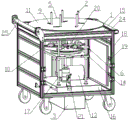
FIG. 1 is a schematic diagram of the structure of the wire coiling device of the present invention;
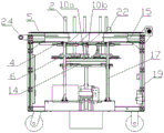
FIG. 2 is a cross-sectional view of the structure of the wire coiling device of the present invention;
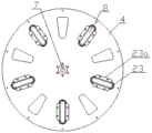
FIG. 3 is a schematic view of the first turntable of the present invention;
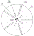
FIG. 4 is a schematic view of a third turntable according to the present invention;
fig. 5 is a schematic diagram of a line card according to the present invention.
As shown in fig. 1 to 5, the turntable assembly 1, the spool 2, the rotary drive device 3, the first turntable 4, the second turntable 5, the third turntable 6, the mounting hole 7, the first guide way 8, the second guide way 9, the sliding pair 10, the slide rail 10a, the slider 10b, the wire placement plane 11, the opening 12, the lifting drive device 13, the lifting platform 14, the upper mounting platform 15, the lower mounting platform 16, the upright 17, the travelling car 18, the frame 19, the upper limit switch 20, the lower limit switch 21, the line clip 22, the main body 22a, the clamping part 22b, the protective cover 23, the mounting part 23a, the handle 24, the roller 25, and the protective sheath 26.
Detailed Description
The invention is described in further detail below with reference to the attached drawings and detailed description:
embodiment one:
as shown in fig. 1 and 2, the present invention provides an automatic wire harness winding device, which comprises a turntable assembly 1, a plurality of winding posts 2 mounted on the turntable assembly 1, and a rotation driving device 3.
Wherein, the rotary driving device 3 drives the turntable assembly 1 to rotate forward or backward, and the coil post 2 and the turntable assembly 1 are configured with each other: during winding, the turntable assembly 1 is controlled to rotate positively, so that all the wire winding columns 2 move outwards to a first position, simultaneously winding is started, a cable is placed on a wire placing plane 11 at the uppermost part of the turntable assembly 1 and is wound along the wire winding columns 2, and the circumferential size enclosed by a plurality of wire winding columns 2 in the process limits the diameter of the wire coil; after the coiling is finished, the rotary table assembly 1 is controlled to rotate reversely, so that all coiling columns 2 move to the center reversely to the second position, all coiling columns 2 are separated from the wire coil, and a worker can conveniently take out the wire.
In order to further facilitate wire taking, the turntable assembly 1 is further provided with a lifting mechanism for adjusting the relative height between the wire placing plane 11 of the turntable assembly 1 and the wire winding column 2. When the winding is finished, the top end of the wire winding column 2 is lower than the wire placing plane 11 or is in the same plane with the wire placing plane 11.
Specifically, in this embodiment, the turntable assembly 1 includes a first turntable 4, a second turntable 5 and a third turntable 6, where the second turntable 5, the first turntable 4 and the third turntable 6 are sequentially disposed from top to bottom, the upper surface of the second turntable 5 is a wire placing plane 11, and the wire harness is placed on the upper surface of the second turntable 5 during winding.
The rotation driving device 3 preferably adopts a servo motor, an output end of the rotation driving device 3 is connected with the first rotating disc 4 and drives the first rotating disc 4 to rotate, as shown in fig. 3, a mounting hole 7 is formed in the center of the first rotating disc 4, the mounting hole 7 is provided with a key groove, and an output end of the servo motor is inserted into the mounting hole 7 and connected through a key.
The first rotating disc 3 is provided with a plurality of first guide channels 8, the second rotating disc 4 is provided with a plurality of second guide channels 9, the first guide channels 8 are perpendicular to the normal direction of the first rotating disc 3, the second guide channels 9 are in one-to-one correspondence with the first guide channels 8, but included angles are formed between the second guide channels 9 and the first guide channels 8, the inclined directions of the plurality of second guide channels 9 are the same, the included angles are determined according to the maximum distance of movement of the coil wire column 2, the included angles between the second guide channels 9 and the first guide channels 8 are preferably 30-60 degrees, more preferably 40-50 degrees, and the optimal value is 47 degrees.
In this embodiment, the first guide way 8 and the second guide way 9 are preferably elongated open slots, the bottom of the wire winding column 2 is slidably connected with the third turntable 5, the wire winding column 2 sequentially passes through the first guide way 8 and the second guide way 9 upwards, and passes out of the second guide way 9 by a certain height for winding, and the wire winding column 2 slides in the corresponding first guide way 8 and second guide way 9 during forward rotation and reverse rotation. In this embodiment, as shown in fig. 4, it is preferable that a plurality of sliding pairs 10 are provided on the third turntable 5, and the sliding pairs are composed of a linear sliding rail 10a and a sliding block 10b sliding along the sliding rail 10a, the sliding rail 10a is fixed on the third turntable 6 by a screw, the sliding rail 10a may be a T-shaped sliding rail or a dovetail sliding rail, a T-shaped or dovetail sliding groove is correspondingly provided on the sliding block 10b, the bottom of the coil post 2 is fixed on the sliding block 10b of the sliding pair 10, the sliding rail 10a is parallel to the first guide way 8, an opening 12 for passing through an output shaft of the servo motor is provided at the center of the third turntable 6, and a nylon material protecting sleeve 26 is fixed at the opening 12 by a screw for ensuring the output shaft passing through. The number of the first guide channels 8, the second guide channels 9 and the sliding pairs 10 is the same as that of the coil posts 2 and is correspondingly arranged.
The first rotating disc 4 is a driving rotating disc, the second rotating disc 4 and the third rotating disc 5 are driven rotating discs, when the rotary driving device 3 drives the first rotating disc 3 to rotate, the middle part of the coil wire column 2 slides in the first guide channel 8, meanwhile, the upper part of the coil wire column 2 slides in the second guide channel 9, the bottom part slides along the sliding rail 10a, and the rotation of the first rotating disc 3 drives the second rotating disc 5 and the third rotating disc 6 to synchronously rotate through the coil wire column 2. Because there is a certain contained angle between first guide way 8 and the second guide way 9, when first carousel 4 drove the rotation of second carousel 5, under the restriction effect of second guide way 9, coil post 2 can follow second guide way 9 and remove, and coil post 2 and then change between first position and second position. The first position is the outer end of the second guide channel 9, the second position is the inner end of the second guide channel 9, that is, when the first rotating disc 4 rotates positively, the second rotating disc 5 is driven to rotate positively, at this time, the coil post 2 slides from the second position to the first position and is limited at the first position, after winding is finished, when the first rotating disc 4 rotates reversely, the second rotating disc 5 is driven to rotate reversely, at this time, the coil post 2 slides from the first position to the second position and is limited at the second position, so that all the coil posts 2 are separated from the coil, and the coil picking of workers is facilitated.
Utilize rotary drive 3 when realizing the rotatory wire winding of second carousel 5, can realize through corotation and the control of reversal again that coil post 2 changes between the first position of wire winding and the second position when getting the line, do not need to set up the rotatory mechanism of wire winding and make coil post break away from the mechanism of drum respectively, simultaneously, when the wire winding of second carousel 5 corotation, the first position that coil post 2 can fix a position all the time under the effect of rotation force and have outside expansion force, be favorable to overcoming the shrinkage force when pencil winding, guarantee that the diameter of drum is standard diameter. The device utilizes a set of rotary mechanism to realize multiple functions simultaneously, so that the whole device is simpler and is easy to operate.
In this embodiment, in order to adjust the relative height between the wire placing plane 11 of the turntable assembly 1 and the wire winding column 2, a first lifting mechanism is connected to the third turntable 6, and the first lifting mechanism drives the third turntable 6 to lift and lower the parallel wire winding column 2.
Specifically, the first lifting mechanism includes a lifting driving device 13 and a lifting platform 14, the third turntable 6 is rotationally connected with the lifting platform 14 through a shaft sleeve (not labeled in the figure), the lifting driving device 13 preferably adopts a screw motor, an output end of the screw motor is fixedly connected with the lifting platform 14, the screw motor drives the lifting platform 14 and the third turntable 6 to lift, and then the coil wire column 2 is driven to lift. During winding, the output end of the control screw motor rotates positively to drive the third rotary table 6 to ascend, and the wire winding column 2 penetrates out of the second rotary table 5 for winding. After the winding end coil post 2 moves to the second position, the output end of the screw motor is controlled to rotate reversely to drive the third rotary table 6 to descend, so that the top of the coil post 2 descends to the position below the wire placing plane 11, and the operator can conveniently take out wires.
The wire coiling device further comprises an upper mounting platform 15 and a lower mounting platform 16, the lifting platform 14 is located between the upper mounting platform 15 and the lower mounting platform 16, the second turntable 5 and the upper mounting platform 15 are rotationally connected through shaft sleeves (not shown in the figure), the lifting driving device 13 is mounted on the lower mounting platform 16, the lifting platform 14 and the upper mounting platform 15 are connected through four vertical upright posts 17, the first turntable 4 and the third turntable 6 are located in the middle of the four upright posts 17, the lifting platform 14 and the upright posts 17 are connected through shaft sleeves, the lifting platform 14 can move up and down relative to the upright posts 17, and the upright posts 17 play a role of supporting and guiding so as to ensure stable rotation and lifting of the third turntable 6 and further ensure the winding quality. In order to control the lifting height of the coil post 2, an upper limit switch 20 and a lower limit switch 21 are further installed on the lifting platform 14, and the upper limit switch 20 and the lower limit switch 21 may take any structural form in the prior art, which will not be described in detail.
In this embodiment, as shown in fig. 1 and fig. 5, a line card 22 is installed in an opening slot of one of the second guide channels 9, the head of the cable is clamped in the line card 22 to facilitate winding, the line card 22 is installed at the inner side of the winding post 2, the line card 22 is detachably clamped in the opening slot, a bayonet is opened on a main body 22a of the line card 22, the end of the wire harness is clamped in the bayonet, a clamping part 22b is arranged below the main body 22a, and the size of the clamping part 22b is matched with the size of the opening slot, so that the wire harness can be directly clamped in the opening slot to realize fixation. Of course, the line cards 22 may also be directly fixed to the second turntable 5.
A polytetrafluoroethylene tube (not shown in the figure) is sleeved on the outer surface of the coil post 2 and used for protecting the coil post 2 from abrasion. Meanwhile, a protective sleeve 23 is also arranged in the open grooves of the first guide way 8 and the second guide way 9 for further protecting the coil post 2. The protecting sleeve 23 is of an annular structure, the shape of the protecting sleeve is matched with that of the open slot, the protecting sleeve is sleeved in the open slot, the two sides of the protecting sleeve 23 outwards extend out of the mounting parts 23a, and the mounting parts 23a are fixed on the second rotary table 5 or the first rotary table 4 through screws.
As shown in fig. 1 and 2, in this embodiment, it is further preferable that all the devices such as the turntable assembly 1 and the rotary drive device 3 are integrally mounted on the travelling car 18, so that the operator can push the wire coiling device to any position of the workshop as required.
The frame 19 of travelling car 18 is box-shaped's structure, installs the handle 24 that is used for the shallow in one side of frame 19, conveniently promotes, and roller bearing 25 is installed to the opposite side of frame 19, and the pencil bypasses roller bearing 25 and is connected with coil post 2, and roller bearing 25's setting is favorable to the pencil steady in motion, guarantees the drum quality. The roller 25 is made of nylon material, so that abrasion of the wire harness is avoided. The top plate of the box-shaped frame 19 serves as an upper mounting platform 15, the second turntable 5 is mounted above the top plate of the frame 19, the rest of the components are all mounted in the box body of the frame 19, and the lower mounting platform 16 is fixed on the bottom plate of the box-shaped frame 19, but the bottom plate of the box-shaped frame 19 can be directly used as the lower mounting platform 16. The servo motor is installed below the bottom plate of the box frame 19, and the servo motor is installed by utilizing the space of the height of the wheels, so that the overall height of the movable trolley 18 is reduced. An inspection door (not shown) is provided on one side of the box frame 19 to facilitate the operator's routine maintenance of the internal equipment.
The operation steps of the device are as follows:
1. the head of the cable is captured within the wire card 22.
2. After the starting button of the device is pressed, the servo motor drives the first rotating disc 4 to rotate positively, the wire winding column 2 moves to a first position (namely the outer end part of the second guide channel 9) with a larger diameter at the outer end of the second rotating disc 6, meanwhile, the second rotating disc 5 and the third rotating disc 6 are driven to rotate positively synchronously under the driving of the wire winding column 2, and the wire harness after the wire winding is orderly wound on the wire winding column 2 to form a disc.
3. After the coiling is finished, the servo motor drives the first rotary disc 4 to rotate reversely, the coiling column 2 moves to a second position (namely the inner end part of the second guide channel 9) with a smaller diameter at the inner end of the second rotary disc 6, and simultaneously, the second rotary disc 5 and the third rotary disc 6 are driven by the coiling column 2 to rotate reversely synchronously.
4. The screw motor is driven to rotate to drive the third turntable 6 to descend, and the linkage drives the coil wire column 2 to descend, so that the coiled wire harness can be taken down from the second turntable 5.
The device overall structure is ingenious, and degree of automation is high, both can realize the wire winding through the rotation of carousel, can also realize standard diameter's location simultaneously, and steerable dish terminal breaks away from the drum after the wire winding finishes, conveniently gets the line, can improve work efficiency by a wide margin.
Embodiment two:
in this embodiment, a limiting member (not shown) is further included in the turntable assembly 1, so as to limit the maximum distance that the coil post 2 moves outwards according to the coil requirements of different standard diameters, i.e. limit the position where the first position is located, thereby further improving the versatility of the device.
The limiting piece can be fixed in the second guide channel 9 through the screw, and the coil wire column 2 maximally moves to the limiting piece when the second turntable 5 rotates positively, so that the limiting piece is easy and convenient to assemble and disassemble.
Of course, the limiting piece can also directly utilize the protecting sleeve 23 provided in the first embodiment, and the protecting sleeve 23 can be of different specifications, namely, the opening lengths of the protecting sleeve 23 are different, so that the maximum moving position of the coil post 2 can be limited, and the protecting sleeve 23 can play a role in protecting the coil post 2 and also play a limiting role.
Embodiment III:
the difference from the first and second embodiments is that in the present embodiment, only the first rotary table 4 and the second rotary table 5 are included, the second rotary table 5 is installed above the first rotary table 4, and the rotation driving device 3 is connected with the first rotary table 4 and drives the first rotary table 4 to rotate forward and backward. In this structure, the first guide channel 8 on the first rotating disc 4 is a sliding pair, the structure of the sliding pair is the same as that described in the first embodiment, the bottom of the coil post 2 is fixedly connected with the sliding block in the sliding pair, the second guide channel 9 on the second rotating disc 5 is a strip-shaped open slot, the top of the coil post 2 passes through the second guide channel 9 upwards, the second guide channel 9 has an included angle with the first guide channel 8, and the rotation relationship between the first rotating disc 4 and the second rotating disc 5 is the same as that described in the first embodiment.
In this embodiment, in order to realize the adjustment of the relative height of the wire winding post 2 and the wire placing plane 11, a second lifting mechanism (not shown in the figure) is connected to the second turntable 5, and the second lifting mechanism also includes a lifting driving device and a lifting platform, and the second turntable 5 is rotatably connected to the lifting platform through a shaft sleeve (not labeled in the figure), and the lifting platform is mounted on the top plate of the frame 19 of the travelling trolley 18. The lifting driving device preferably adopts a screw motor, the output end of the screw motor is fixedly connected with the lifting platform, the screw motor drives the lifting platform to lift, and then the second turntable 5 is driven to lift, so that the relative height between the wire coiling column 2 and the wire placing plane 11 is adjusted.
During winding, the output end of the screw motor is controlled to rotate to drive the second rotary table 5 to descend, and the wire winding column 2 penetrates out of the second rotary table 5 for winding. After the winding end coil post 2 moves to the second position, the output end of the control screw motor reversely rotates to drive the second rotary table 5 to ascend, so that the upper surface of the second rotary table 5 is higher than the top of the coil post 2, and the operator can conveniently take a wire.
As mentioned above, similar technical solutions can be derived from the solution content presented in connection with the figures. However, any simple modification, equivalent variation and modification of the above embodiments according to the technical substance of the present invention still fall within the scope of the technical solution of the present invention.
Claims (9)
1. An automatic wire coiling device for a wire harness is characterized in that: the wire winding device comprises a turntable assembly, a plurality of wire winding columns and a rotary driving device, wherein the wire winding columns are arranged on the turntable assembly, the rotary driving device drives the turntable assembly to rotate forwards or reversely, the wire winding columns and the turntable assembly are configured to move to a first position and wind wires when the turntable assembly rotates forwards, and move to a second position to separate the wire winding columns from a wire coil when the turntable assembly rotates reversely; the rotary table assembly comprises a first rotary table and a second rotary table, the second rotary table is arranged above the first rotary table, the rotary driving device is connected with the first rotary table and drives the first rotary table to rotate, a plurality of first guide channels are arranged on the first rotary table, a plurality of second guide channels are arranged on the second rotary table, the first guide channels are perpendicular to the normal direction of the first rotary table, an included angle is formed between the second guide channels and the first guide channels, and the wire column is connected with the first guide channels and the second guide channels in a sliding mode and is converted between a first position and a second position.
2. An automatic wire harness winding device according to claim 1, wherein: the lifting mechanism is arranged on the turntable assembly and used for adjusting the relative height between the wire placing plane of the turntable assembly and the wire placing column, so that the wire placing column is higher than the wire placing plane during winding, and the topmost end of the wire placing column is lower than the wire placing plane or is in the same plane with the wire placing plane when wire taking is finished during winding.
3. An automatic wire harness winding device according to claim 2, wherein: a third turntable is arranged below the first turntable, the bottom of the coil post is in sliding connection with the third turntable, a first lifting mechanism is connected to the third turntable, the first lifting mechanism drives the third turntable to lift and drop the coil post in parallel, and the first turntable drives the third turntable to synchronously rotate through the coil post when rotating;
or, the second turntable is connected with a second lifting mechanism, and the second lifting mechanism drives the second turntable to lift.
4. An automatic wire harness winding device according to claim 3, wherein: the third turntable is provided with a plurality of sliding pairs, the sliding rails of the sliding pairs are parallel to the first guide channels, the first guide channels and the second guide channels are elongated open grooves, and the bottoms of the wire coiling columns are fixed on the sliding blocks of the sliding pairs and sequentially penetrate through the first guide channels and the second guide channels upwards.
5. An automatic wire harness winding device according to claim 3, wherein: the first lifting mechanism and the second lifting mechanism comprise lifting driving devices and lifting platforms, the second turntable or the third turntable is rotationally connected with the corresponding lifting platform, and the lifting driving devices drive the lifting platform and the corresponding second turntable or the third turntable to lift.
6. An automatic wire harness winding device according to claim 1, wherein: the included angle between the second guide channel and the first guide channel is 30-60 degrees.
7. An automatic wire harness winding device according to claim 1, wherein: the second position is the inner side end part of the second guide channel, and the first position is the outer side end part of the second guide channel; or, a limiting piece is arranged on at least one of the second guide way or the first guide way, and the limiting piece is used for limiting the position of the first position on the first guide way or the second guide way.
8. An automatic wire harness winding device according to any one of claims 1 to 7, wherein: the turntable assembly and the rotary driving device are arranged on the movable trolley, and the frame is of a box-shaped structure.
9. The automatic wire harness winding device according to claim 8, wherein: one side of the frame is provided with a handle, the other side of the frame is provided with a rolling shaft, and the wire harness bypasses the rolling shaft and is connected with the wire coiling column.
Priority Applications (1)
| Application Number | Priority Date | Filing Date | Title |
|---|---|---|---|
| CN202010487382.0A CN113753661B (en) | 2020-06-02 | 2020-06-02 | Automatic wire coiling device for wire harness |
Applications Claiming Priority (1)
| Application Number | Priority Date | Filing Date | Title |
|---|---|---|---|
| CN202010487382.0A CN113753661B (en) | 2020-06-02 | 2020-06-02 | Automatic wire coiling device for wire harness |
Publications (2)
| Publication Number | Publication Date |
|---|---|
| CN113753661A CN113753661A (en) | 2021-12-07 |
| CN113753661B true CN113753661B (en) | 2023-05-30 |
Family
ID=78782767
Family Applications (1)
| Application Number | Title | Priority Date | Filing Date |
|---|---|---|---|
| CN202010487382.0A Active CN113753661B (en) | 2020-06-02 | 2020-06-02 | Automatic wire coiling device for wire harness |
Country Status (1)
| Country | Link |
|---|---|
| CN (1) | CN113753661B (en) |
Families Citing this family (1)
| Publication number | Priority date | Publication date | Assignee | Title |
|---|---|---|---|---|
| CN115285793B (en) * | 2022-08-11 | 2023-04-07 | 索尔集团股份有限公司 | Wiring stabilizing device and wiring stabilizing method for electric wires and cables |
Citations (1)
| Publication number | Priority date | Publication date | Assignee | Title |
|---|---|---|---|---|
| CN210339941U (en) * | 2019-07-02 | 2020-04-17 | 天津华源时代金属制品有限公司 | Galvanized wire winding coil forming device |
Family Cites Families (8)
| Publication number | Priority date | Publication date | Assignee | Title |
|---|---|---|---|---|
| US6533205B1 (en) * | 2001-08-31 | 2003-03-18 | Stocker Yale, Inc. | Fiber optic cable winding tool |
| CN204714155U (en) * | 2015-01-09 | 2015-10-21 | 深圳市奥科斯特智能装备股份有限公司 | Inventory belting |
| CN105645175B (en) * | 2016-03-31 | 2018-08-17 | 中特科技工业(青岛)有限公司 | A kind of fully automatic wire winding machine |
| CN205855583U (en) * | 2016-07-29 | 2017-01-04 | 浙江六环电线电缆有限公司 | A kind of cable automatic coiling apparatus |
| CN206108570U (en) * | 2016-08-31 | 2017-04-19 | 厦门银佳华电子设备有限公司 | Inner circle can self -adjusting winding device |
| CN206569812U (en) * | 2017-03-10 | 2017-10-20 | 福建海峡科化股份有限公司 | One kind is around pipe mechanism |
| CN108083013B (en) * | 2018-01-27 | 2024-05-28 | 山东建筑大学 | Automatic plastic pipe coiling machine |
| CN209758755U (en) * | 2019-04-01 | 2019-12-10 | 中车唐山机车车辆有限公司 | Wire coiling and wiring device |
-
2020
- 2020-06-02 CN CN202010487382.0A patent/CN113753661B/en active Active
Patent Citations (1)
| Publication number | Priority date | Publication date | Assignee | Title |
|---|---|---|---|---|
| CN210339941U (en) * | 2019-07-02 | 2020-04-17 | 天津华源时代金属制品有限公司 | Galvanized wire winding coil forming device |
Non-Patent Citations (1)
| Title |
|---|
| 基于PLC绕线机控制系统设计;杨涛等;组合机床与自动化加工技术(第08期);第58-59页 * |
Also Published As
| Publication number | Publication date |
|---|---|
| CN113753661A (en) | 2021-12-07 |
Similar Documents
| Publication | Publication Date | Title |
|---|---|---|
| FI77827B (en) | ANORDNING FOER UPPLINDNING AV EN KABEL PAO EN KABELTRUMMA. | |
| CN205004184U (en) | Vertical coil winding machine | |
| CN105118661A (en) | Vertical winding machine | |
| CN113753661B (en) | Automatic wire coiling device for wire harness | |
| CN214495218U (en) | Communication cable winding device for electrical engineering | |
| CN107838334A (en) | A kind of quick separate winder of power line copper wire | |
| CN112645141A (en) | Combined wire winding unit for cable processing | |
| CN117253717B (en) | Winding equipment and winding process for dry-type transformer | |
| CN117124903A (en) | Multi-potential charging station with adjustable | |
| CN113523138B (en) | Product rack convenient to unload for bending machine | |
| CN107785163B (en) | Wireless charging coil outgoing line winding complete machine | |
| CN212655275U (en) | Material collecting device of wire and cable wrapping machine | |
| CN210824826U (en) | Novel cable winding device | |
| CN109585159B (en) | Wireless charging coil outlet and winding integrated mechanism | |
| CN218447538U (en) | Winding equipment for manufacturing magnetic yoke transformer | |
| CN111243857A (en) | Inductance coil and winding method and winding machine thereof | |
| CN212049857U (en) | Cable pay-off device | |
| CN110950164A (en) | Electric power engineering's hank mill | |
| CN217994901U (en) | Equipment for bundling AC power supply line | |
| CN212257034U (en) | Single-group twisted pair wire twisting machine | |
| CN219554791U (en) | Motor wire harness winding device | |
| CN216794814U (en) | Winding device for stator | |
| CN220492833U (en) | Automatic winding machine | |
| CN217458246U (en) | Axle type wire rewinding machine | |
| CN112837926B (en) | Small-size reactor coil winding mechanism |
Legal Events
| Date | Code | Title | Description |
|---|---|---|---|
| PB01 | Publication | ||
| PB01 | Publication | ||
| SE01 | Entry into force of request for substantive examination | ||
| SE01 | Entry into force of request for substantive examination | ||
| GR01 | Patent grant | ||
| GR01 | Patent grant |