CN113748308A - Receiving and releasing thermal energy - Google Patents
Receiving and releasing thermal energy Download PDFInfo
- Publication number
- CN113748308A CN113748308A CN202080033568.7A CN202080033568A CN113748308A CN 113748308 A CN113748308 A CN 113748308A CN 202080033568 A CN202080033568 A CN 202080033568A CN 113748308 A CN113748308 A CN 113748308A
- Authority
- CN
- China
- Prior art keywords
- valves
- temperature
- valve
- fluid
- inlet
- Prior art date
- Legal status (The legal status is an assumption and is not a legal conclusion. Google has not performed a legal analysis and makes no representation as to the accuracy of the status listed.)
- Pending
Links
- 239000012530 fluid Substances 0.000 claims abstract description 151
- 239000011232 storage material Substances 0.000 claims abstract description 57
- 238000007599 discharging Methods 0.000 claims abstract description 49
- 238000000034 method Methods 0.000 claims description 54
- 238000011144 upstream manufacturing Methods 0.000 claims description 8
- 239000000126 substance Substances 0.000 claims description 2
- 238000009826 distribution Methods 0.000 description 16
- 238000003860 storage Methods 0.000 description 10
- 239000013529 heat transfer fluid Substances 0.000 description 9
- 230000006870 function Effects 0.000 description 6
- 238000005338 heat storage Methods 0.000 description 5
- 230000000694 effects Effects 0.000 description 4
- 239000000463 material Substances 0.000 description 3
- 238000009529 body temperature measurement Methods 0.000 description 2
- 238000004146 energy storage Methods 0.000 description 2
- 230000014509 gene expression Effects 0.000 description 2
- 230000005484 gravity Effects 0.000 description 2
- 239000004575 stone Substances 0.000 description 2
- 238000012935 Averaging Methods 0.000 description 1
- 238000003491 array Methods 0.000 description 1
- 230000006399 behavior Effects 0.000 description 1
- 230000015572 biosynthetic process Effects 0.000 description 1
- 239000000919 ceramic Substances 0.000 description 1
- 238000006243 chemical reaction Methods 0.000 description 1
- 230000001351 cycling effect Effects 0.000 description 1
- 230000001419 dependent effect Effects 0.000 description 1
- 239000007789 gas Substances 0.000 description 1
- 238000010438 heat treatment Methods 0.000 description 1
- 238000004519 manufacturing process Methods 0.000 description 1
- 230000005855 radiation Effects 0.000 description 1
- 238000011084 recovery Methods 0.000 description 1
- 239000011435 rock Substances 0.000 description 1
- 239000013589 supplement Substances 0.000 description 1
- 239000002918 waste heat Substances 0.000 description 1
Images


Classifications
-
- F—MECHANICAL ENGINEERING; LIGHTING; HEATING; WEAPONS; BLASTING
- F28—HEAT EXCHANGE IN GENERAL
- F28D—HEAT-EXCHANGE APPARATUS, NOT PROVIDED FOR IN ANOTHER SUBCLASS, IN WHICH THE HEAT-EXCHANGE MEDIA DO NOT COME INTO DIRECT CONTACT
- F28D20/00—Heat storage plants or apparatus in general; Regenerative heat-exchange apparatus not covered by groups F28D17/00 or F28D19/00
- F28D20/0056—Heat storage plants or apparatus in general; Regenerative heat-exchange apparatus not covered by groups F28D17/00 or F28D19/00 using solid heat storage material
-
- F—MECHANICAL ENGINEERING; LIGHTING; HEATING; WEAPONS; BLASTING
- F28—HEAT EXCHANGE IN GENERAL
- F28D—HEAT-EXCHANGE APPARATUS, NOT PROVIDED FOR IN ANOTHER SUBCLASS, IN WHICH THE HEAT-EXCHANGE MEDIA DO NOT COME INTO DIRECT CONTACT
- F28D17/00—Regenerative heat-exchange apparatus in which a stationary intermediate heat-transfer medium or body is contacted successively by each heat-exchange medium, e.g. using granular particles
- F28D17/04—Distributing arrangements for the heat-exchange media
-
- F—MECHANICAL ENGINEERING; LIGHTING; HEATING; WEAPONS; BLASTING
- F28—HEAT EXCHANGE IN GENERAL
- F28D—HEAT-EXCHANGE APPARATUS, NOT PROVIDED FOR IN ANOTHER SUBCLASS, IN WHICH THE HEAT-EXCHANGE MEDIA DO NOT COME INTO DIRECT CONTACT
- F28D20/00—Heat storage plants or apparatus in general; Regenerative heat-exchange apparatus not covered by groups F28D17/00 or F28D19/00
- F28D20/02—Heat storage plants or apparatus in general; Regenerative heat-exchange apparatus not covered by groups F28D17/00 or F28D19/00 using latent heat
- F28D20/028—Control arrangements therefor
-
- F—MECHANICAL ENGINEERING; LIGHTING; HEATING; WEAPONS; BLASTING
- F28—HEAT EXCHANGE IN GENERAL
- F28F—DETAILS OF HEAT-EXCHANGE AND HEAT-TRANSFER APPARATUS, OF GENERAL APPLICATION
- F28F27/00—Control arrangements or safety devices specially adapted for heat-exchange or heat-transfer apparatus
- F28F27/006—Control arrangements or safety devices specially adapted for heat-exchange or heat-transfer apparatus specially adapted for regenerative heat-exchange apparatus
-
- F—MECHANICAL ENGINEERING; LIGHTING; HEATING; WEAPONS; BLASTING
- F28—HEAT EXCHANGE IN GENERAL
- F28F—DETAILS OF HEAT-EXCHANGE AND HEAT-TRANSFER APPARATUS, OF GENERAL APPLICATION
- F28F27/00—Control arrangements or safety devices specially adapted for heat-exchange or heat-transfer apparatus
- F28F27/02—Control arrangements or safety devices specially adapted for heat-exchange or heat-transfer apparatus for controlling the distribution of heat-exchange media between different channels
-
- Y—GENERAL TAGGING OF NEW TECHNOLOGICAL DEVELOPMENTS; GENERAL TAGGING OF CROSS-SECTIONAL TECHNOLOGIES SPANNING OVER SEVERAL SECTIONS OF THE IPC; TECHNICAL SUBJECTS COVERED BY FORMER USPC CROSS-REFERENCE ART COLLECTIONS [XRACs] AND DIGESTS
- Y02—TECHNOLOGIES OR APPLICATIONS FOR MITIGATION OR ADAPTATION AGAINST CLIMATE CHANGE
- Y02E—REDUCTION OF GREENHOUSE GAS [GHG] EMISSIONS, RELATED TO ENERGY GENERATION, TRANSMISSION OR DISTRIBUTION
- Y02E60/00—Enabling technologies; Technologies with a potential or indirect contribution to GHG emissions mitigation
- Y02E60/14—Thermal energy storage
Abstract
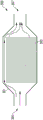
Described is a device (100) for receiving and/or releasing, in particular storing, thermal energy, comprising: a container (101) for holding a storage material (103), the container having a first fluid port (105) and a second fluid port (107) for allowing inflow and outflow of a fluid (109) flowing through the container in a substantially horizontal flow direction (111,112) for charging and/or discharging the storage material (103); at least two first valves (V1b, V1d) located at different vertical positions of the first fluid port (105); at least two second valves (V2b, V2d) located at different vertical positions of the second fluid port (107); and at least two temperature sensors (T1b, T1d) arranged within the container (101) at different vertical positions, in particular in one plane (P1) perpendicular to the flow direction.
Description
Technical Field
The present invention relates to a device and a method for receiving and/or releasing thermal energy, in particular comprising storing thermal energy.
Background
WO 2016/150456a1 discloses a thermal energy storage apparatus comprising a container comprising a heat storage material, having an inlet comprising a plurality of inlet channels distributed in a direction orthogonal to the longitudinal direction of the container, wherein each of the inlet channels has a respective actively controlled valve. Furthermore, the container comprises an outlet comprising a plurality of outlet passages distributed in a direction orthogonal to the longitudinal direction, each of the outlet passages having a respective active control valve.
The prior art solution is to convert the fluctuating electrical energy from the wind and/or solar generator into heat for later reconversion back into electrical energy. This flattens the power peaks that occur in national power grids and supplies electrical energy at low wind and/or low solar radiation, which makes these grids controllable and prevents blackouts.
In order to be able to convert electrical energy into heat and subsequently back into electrical energy, in addition to conventional process equipment for energy conversion (e.g. electric heaters and water-steam cycles with heat recovery steam generators), a thermal storage is required which is able to store heat for a sufficiently long period of time to flatten the above-mentioned peaks. For this purpose, a horizontal sensible heat store may be used, which contains a storage material that can be heated by a gaseous heat transfer fluid, such as air, which is actively moved through the thermal store. Such storage material may be stone and/or gravel.
When charging the thermal store, the heat transfer fluid is heated, for example by an electric heater, enters the thermal store at a high temperature on the hot side, transfers heat to the storage material, and leaves the thermal store at a lower temperature on the cold side. The charging process at the cold side is terminated when the outlet temperature reaches a certain level, which may be defined, for example, by material temperature limitations of the process equipment.
When heat is released, the direction of flow through the reservoir is reversed. The heat transfer fluid enters the thermal storage at a low temperature on the cold side of the thermal storage, absorbs heat from the storage material, and leaves the thermal storage at a higher temperature on the hot side. The heat release process is stopped each time the heat release temperature of the heat storage drops below a certain level. The heat release stop temperature is defined by a downstream heat utilization process, which in the case of power production may be a water-steam-or organic-rankine-cycle. Due to this cycling between the two temperature levels, some waste heat remains inside the heat store during each heat release. The more vertically/evenly distributed the temperature front between the hot and cold ends of the reservoir, and the steeper the temperature gradient, the less amount of heat remains in the reservoir after the heat release, and therefore, the better the utilization of the entire charge and discharge cycle.
In fact, the temperature front is not vertical due to natural convection and heat flow processes. Misallocation of flows may occur for several reasons. When using air as the heat transfer fluid, a higher temperature results in a lower density, which causes the hot air to rise and the cold air to fall. Therefore, the temperature of the upper storage material rises faster. Eventually, the hot side of the temperature front reaches the cold side of the heat storage, so that hot air will leave at the cold side when charging. This results in a higher overall temperature of the exiting fluid. In the open cycle this leaving heat is lost, while in the closed cycle it still results in a faster termination of the charging process and thus a lower energy content (capacity). When discharging, some cold air will leave the heat storage at its hot side, which also leads to a faster termination and poorer performance of the heat discharging process and energy losses due to the mixing of hot and cold air.
Natural convection causes another effect. The higher density of the heat transfer fluid due to the lower temperature results in a smaller flow rate and a lower pressure drop in the cold storage material. The heat transfer fluid preferably flows through the cooler storage material due to the lower pressure drop. During periods of heat release, this behavior is undesirable because the hot region of the storage is not flowed through and capacity is lost. Another effect that occurs in horizontal heat stores having stones and/or gravel as the storage material is the formation of gaps between the storage material and the top plate of the heat store due to settling of the bed. The gap has a lower flow resistance than the storage material. This results in a higher mass flow rate so that less heat transfer fluid actually flows through the storage material to transfer heat. The bypass flow supports an inclined temperature front formed by natural convection when charging and at the same time does not transfer as much heat as the mass flow through the storage material. This results in even higher temperatures of the exiting fluid stream when charging and even lower temperatures of the exiting fluid stream when discharging. Both of these effects result in a less efficient overall charge-discharge cycle.
A prior art solution that addresses at least the effects of natural convection on the temperature front is a vertical pebble bed thermal store. However, vertical storage is limited in height because the total mass of stored material must be carried by the flow distribution apparatus.
Therefore, there may be a need for an apparatus and a method for receiving and/or releasing, in particular storing, thermal energy, wherein the efficiency of the charging and/or discharging process is increased. In particular, there may be a need for methods and apparatus in which a more uniform temperature distribution is achieved within a container containing a storage material during charging and/or discharging.
This need may be met by the subject matter according to the independent claims. Advantageous embodiments of the invention are described by the dependent claims.
Disclosure of Invention
According to an embodiment of the invention, there is provided an apparatus for receiving and/or releasing (in particular also storing) thermal energy, comprising: a container for holding a storage material, the container having a first fluid port and a second fluid port for allowing the inflow and outflow of fluid flowing through the container in a substantially horizontal flow direction for charging and/or discharging the storage material; at least two first valves in different vertical positions for the first fluid port; at least two second valves in different vertical positions for the second fluid port; and at least two temperature sensors arranged at different vertical positions (in particular in at least one plane perpendicular to the flow direction) within the container.
The device may also be configured for storing thermal energy in a storage material that may be contained within the container. When receiving thermal energy, at least a portion of the thermal energy of the fluid may be transferred to and stored in the storage material, i.e. the storage material is charged with heat. When thermal energy is released, at least a portion of the thermal energy stored in the storage material may be transferred to the flowing fluid, thereby causing the storage material to release heat.
The container may have any shape, such as a cubic shape, a cylindrical shape, or other shapes. The container may have a longitudinal axis which may coincide with the flow direction of the fluid flowing in the horizontal direction. The flow direction is in particular different from the vertical direction. The storage material may be any material capable of storing thermal energy, in particular having a high heat capacity. The storage material may for example comprise volcanic rock and/or ceramic.
The first fluid port may be used as an inlet port or an outlet port depending on whether charging or discharging of the storage material is performed. The second fluid port may be used as an outlet or an inlet depending on whether charging or discharging of the storage material is performed. The first fluid port and the second fluid port may have any shape, such as a rectangular shape, a cylindrical shape, or the like. The first fluid port may be formed by a single opening or a plurality of openings, such as being configured as a plurality of individual openings formed, for example, by several pipe ends or the like. The second fluid port may in particular be configured similar to or identical to the first fluid port. The first and second fluid ports may allow fluid to enter or exit the interior chamber of the container during charging and/or discharging (receiving and/or releasing) thermal energy. The fluid may in particular comprise air or a specific gas. To charge the storage material (i.e., receive thermal energy), the fluid may be relatively hot, having a temperature between 300 ℃ and 1000 ℃. When flowing through a container having a storage material therein, a portion of the thermal energy of the fluid is transferred to the storage material. When exothermic to the storage material, the fluid may be relatively cold, e.g. having a temperature of between 0 ℃ and 300 ℃. When a cold fluid flows through a vessel having a storage material therein, in particular when the storage material is charged with thermal energy, a portion of the thermal energy stored in the storage material can be transferred to the fluid, thereby heating the fluid. During charging and discharging of the storage material, the flow directions may be in the horizontal direction in both cases, but may be opposite to each other. Thus, during charging, hot fluid may enter at the first fluid port and exit at the second fluid port, while during discharging, cold fluid may enter at the second fluid port and exit at the first fluid port. Thus, the first fluid port and the second fluid port may serve as an inlet or an outlet depending on the process being performed, i.e. depending on whether a charging process or a discharging process is performed.
The at least two valves may each comprise a flap or a cover which can be moved, in particular rotated or tilted, in order to allow or inhibit the flow of fluid. Each of the valves, i.e. each of the at least two first valves and the two second valves, may be set to different states defining an opening degree or a closing degree. The at least two first valves and the at least two second valves are in different vertical positions, wherein the vertical position or vertical direction is perpendicular to the horizontal direction. Thus, the two first valves are at different heights, and the second valve is also at a different height. The at least two first valves may be controllable independently of each other. The second valves may also be controlled independently of each other.
During charging of the storage material, typically the temperature of the storage material may increase with increasing height. In order to achieve a more even temperature distribution (in the vertical direction), the lower one of the first valves may be controlled to open more than the upper one of the two first valves, so as to achieve a substantially higher flow rate of the fluid in the lower part of the container than in the upper part of the container. Thus, having two independently controllable first valves in different vertical positions may allow for a more even temperature distribution in the vertical direction. This can improve the heat charging efficiency.
Similarly, during a heat release (where the second fluid port may act as or be an inlet), when the temperature of the fluid exiting the vessel is relatively hotter, a respective one of the second valves (at the inlet during the heat release) may be more closed than the other of the two second valves. Thus, the efficiency during heat release can also be increased when at least two second valves are provided for the second fluid ports at different vertical positions.
The two first valves may completely restrict fluid flow through or into the first fluid port. The second two valves may fully control fluid flow into or through the second fluid port.
The at least two temperature sensors may be arranged in at least one plane perpendicular to the flow direction, i.e. in one plane perpendicular to the horizontal direction, within the container. By having at least two temperature sensors in the container, advantageously temperature values can be measured and used for controlling the at least two first valves and/or the at least second valve. Thus, in particular, an uneven temperature distribution in or along the vertical direction may be detected or even quantified, allowing more precise control of the two first valves and/or the two second valves in order to improve the efficiency of the device during heat release and/or heat charge. The two temperature sensors may be arranged in a single plane perpendicular to the flow direction, or for example, in two planes perpendicular to the flow direction spaced apart along the horizontal direction as the flow direction.
According to an embodiment of the invention, the first fluid port is formed by at least two first fluid port members arranged at different vertical positions, the fluid flow through each of the two first fluid port members being controlled by one of the two first valves, and/or wherein the second fluid port is formed by at least two second fluid port members arranged at different vertical positions, the fluid flow through each of the two second fluid port members being controlled by one of the two second valves.
The number of first fluid port members may be equal to the number of first valves. The number of second fluid port members may be equal to the number of second valves. In particular, each of the first fluid port members may have an associated first valve that controls the flow of fluid through or to the respective first fluid port member. Each of the second fluid port members may have an associated second valve that may control the flow of fluid through or to the respective second fluid port member.
The first and/or second fluid port members may be constructed or formed, for example, from tube segments or different individual openings in the vessel wall. When the first fluid port member is in different vertical positions, fluid may be supplied to or into the container at different heights in the controlled member, for example to achieve a more uniform temperature distribution during charging. When the second fluid port member is arranged in different vertical positions, also during heat release, fluid may be fed into the container at different heights, thereby also allowing a more uniform temperature distribution during heat release by suitably controlling the at least two second valves.
According to an embodiment of the invention, the device further comprises at least two further temperature sensors arranged within the container at different vertical positions and in at least one further plane perpendicular to the flow direction.
When the at least two further temperature sensors are arranged at a further plane different from the plane in which the at least two temperature sensors are arranged, the temperature change along the flow direction, i.e. the horizontal direction, may also be measurable, thereby in particular allowing to measure or determine the temperature distribution over the three-dimensional space within the container. Thus, the control of the first valve and/or the second valve may still be improved.
According to an embodiment of the invention, there is therefore at least one temperature sensor within the container for each of the at least two second valves and the at least two first valves, which is arranged downstream of the respective valve in the charging flow direction and in the discharging flow direction. When a temperature sensor is arranged downstream of the valve, the temperature of the fluid flowing through the valve is measurable, thereby providing an advantageous control parameter. For example, it may be desirable to achieve a relatively uniform (constant) temperature distribution in the vertical direction, which may be achieved by opening or closing the valves differently in different vertical positions (upstream of the respective temperature sensor).
During charging, the at least two first valves may serve as inlet valves and the associated temperature sensors may be arranged together with the container. During charging, the two second valves may act as outlet valves and the associated temperature sensors may be arranged outside the container, e.g. within or at the respective second fluid port member. During the heat release, the two second valves may act as inlet valves and the respective associated temperature sensors may be arranged within the container. During heat release, both first valves may act as outlet valves, and the respective temperature sensors may be disposed outside the vessel (e.g., within or at the first fluid port member).
The at least one temperature sensor arranged downstream of the valve in question may be arranged substantially at the same vertical position or height as the valve, in order to be able to detect the temperature of the fluid that has passed through the respective valve.
According to an embodiment of the invention, for each valve (of the at least two second valves and the at least two first valves), the at least two temperature sensors or the at least two external temperature sensors arranged outside the container comprise: at least one temperature sensor arranged downstream of the valve in the charging and/or discharging flow direction, and in particular arranged such that a temperature related to the temperature of the fluid flowing through the valve is measurable, wherein the at least one temperature sensor arranged downstream of the valve is in particular arranged substantially in the same lateral area as the valve.
According to an embodiment of the invention, the at least two first valves comprise at least four first valves distributed in a first plane substantially perpendicular to the flow direction and spaced apart in two different lateral directions, and/or wherein the at least two second valves comprise at least four second valves distributed in a second plane substantially perpendicular to the flow direction and spaced apart in two different lateral directions.
When four first valves are provided, these have not only different vertical positions but also, for example, different horizontal positions (in particular different positions in the horizontal direction perpendicular to the flow direction), and by appropriately controlling the respective valves, uneven temperature distribution in the horizontal direction perpendicular to the flow direction can also be reduced. This may be applied only during charging or only during discharging, or it may be applied to both discharging and charging processes.
According to an embodiment of the invention, the first fluid port serves as a fluid inlet during charging and as a fluid outlet during discharging, wherein the second fluid port serves as a fluid outlet during charging and as a fluid inlet during discharging, wherein the at least two first valves serve as inlet valves during charging and as outlet valves during discharging, wherein the at least two second valves serve as outlet valves during charging and as inlet valves during discharging.
Although the expressions "first fluid port, second fluid port, first valve, second valve" refer to structural features of the device, the expressions "fluid inlet, fluid outlet, outlet valve, inlet valve" refer to different functions that the end ports of different valves may have. Thereby supporting the heat release and heat charging of the device.
According to an embodiment of the invention, the device further comprises a valve controller (e.g. for each valve having a valve controller portion) adapted to control at least one of the two first valves and/or the two second valves used as inlet valves based on at least one temperature value measured by at least one of the temperature sensors arranged downstream of the at least one inlet valve. For example, two valve controller portions may control two valves.
For example, during charging, the valve controller may exclusively control the first valve, while during discharging, the valve controller may exclusively control the second valve, while not controlling the remaining valves. Controlling the respective inlet valve may be more important than controlling the respective outlet valve. However, according to other embodiments of the invention, the respective outlet valve may also be controlled by the valve controller.
When only the respective inlet or outlet valve is controlled, the control method can be simplified and, in particular, also fewer temperature values can be required. In particular, only the temperature value of the temperature sensor installed downstream of the respective inlet valve may be considered.
According to an embodiment of the invention, the valve controller is adapted to control at least one of the two first valves and/or the two second valves to act as an outlet valve based on at least one temperature value measured by at least one of the temperature sensors arranged downstream of the at least one outlet valve.
According to an embodiment of the invention, the valve controller is realized as a centralized controller or a decentralized controller, having a controller part for each valve. In particular, all inlet valves are controlled by a valve controller. Hereinafter, the valve controller portion may be collectively referred to as a valve controller.
In particular, the valve controller may be configured to exclusively control the respective outlet valve without controlling the respective inlet valve. However, according to a particular embodiment of the invention, the controller is configured to control both the respective inlet and outlet valves during heat release and/or heat charge. For controlling the outlet valve, use may be made of a temperature value measured by a temperature sensor arranged outside the container.
According to an embodiment of the invention, the valve controller is adapted to control the inlet valve and/or the outlet valve during the charging process so as to dynamically: opening more of the inlet valve having a lower downstream temperature and/or a lower temperature of the fluid flowing through the valve than the inlet valve having a higher downstream temperature and/or a higher temperature of the fluid flowing through the valve, and/or opening more of the outlet valve having a lower upstream temperature and/or a lower temperature of the fluid flowing through the valve than the outlet valve having a higher upstream temperature and/or a higher temperature of the fluid flowing through the valve. Thereby, a more uniform or even or constant temperature distribution across the vertical direction may be achieved.
According to an embodiment of the invention, the valve controller is configured to control at least one of the inlet valves during charging and/or during discharging, comprising: determining an actual temperature value (also referred to as a "process value") associated with the inlet valve; and determining an inlet valve setting signal (for each of the inlet valves) based on a deviation between an actual temperature value associated with the inlet valve and an inlet target value for temperature, in particular using a PI or PID controller.
The actual temperature value associated with the inlet valve may be the temperature value associated with the inlet valve under consideration (or the inlet fluid port member under consideration). The actual temperature value associated with an inlet valve can be determined as the temperature downstream of the respective inlet valve, which is essentially in the same vertical position or vertical height region or same height region, and in particular also in the same or a similar lateral region, as the inlet valve in question. The target value of the temperature may be a predetermined value, which may particularly apply to all existing inlet valves, and which may for example be arranged in a substantially single plane, or may be arranged substantially at the same horizontal position along the flow direction.
The inlet valve setting signal may define the degree of opening or closing of the respective valve. The inlet valve setting signal may be supplied to the respective inlet valve, causing the inlet valve to be adjusted accordingly. The PI controller may be a proportional integral controller having parameters for the controller parameters of the proportional and integral terms. Thus, conventionally available controllers may be utilized.
According to an embodiment of the invention, controlling at least one of the inlet valves comprises: determining a plane and/or location along the flow direction at which the temperature (e.g., highest temperature on the plane) reaches a predetermined fraction of the temperature associated with charging or the temperature associated with discharging; determining an actual temperature value ("process value") associated with the inlet valve based on at least one temperature (e.g., an average of at least one temperature) measured by at least one temperature sensor arranged in a determined plane/position in the same/overlapping lateral region as the inlet valve; an inlet target temperature value ("target value") for all inlet valves is determined as a predetermined fraction of the maximum value for the charge and the minimum value for the discharge of the actual temperature values associated with the inlet valves.
The determined plane and/or location along the flow direction at which the temperature reaches a predetermined fraction of the temperature associated with charging or the temperature associated with discharging may also be referred to as a temperature front plane. The plane and/or position may change during the execution of the heat release or heat charge process and may be updated by a controller or control method. The determined plane and/or position in the flow direction may be downstream of an inlet valve for which the actual temperature value is determined.
During charging, a predetermined fraction of the maximum value of the actual temperature values associated with the inlet values is used as an inlet target value for the temperature of all inlet valves. During the heat release, a predetermined fraction of the minimum of the actual temperature values associated with the inlet valve is used as an inlet target value for the temperature. According to other embodiments, different inlet target values may be defined for different inlet valves. The actual temperature value associated with the inlet valve may for example be determined as an average, in particular a weighted average, of the temperature values measured by the temperature sensors arranged in a determined plane/position (in particular a front temperature plane) in the same or overlapping lateral region as the inlet valve under consideration.
According to an embodiment of the invention, the valve controller is configured to control at least one of the outlet valves during charging and/or during discharging, comprising: determining an actual temperature value (also referred to as a "process value") associated with the outlet valve; the outlet valve setting signal is determined (for each outlet valve) based on the deviation between the actual temperature value associated with the outlet valve and the outlet target value of the temperature, in particular using a PI or PID controller.
Thus, the outlet valve may also be controlled separately or additionally, i.e. during charging and/or during discharging.
According to an embodiment of the invention, controlling at least one of the outlet valves comprises: determining an actual temperature value ("process value") associated with the outlet valve based on at least one temperature (e.g. an average thereof) measured by at least one temperature sensor arranged downstream of the outlet valve, in the same/overlapping lateral region as the outlet valve; an outlet target value ("target value") for the temperature of all outlet valves is determined as a predetermined fraction of the minimum value for the heat charge and the maximum value for the heat release of the actual temperature values associated with the outlet valves.
The actual temperature value associated with the outlet valve may for example be determined as an average, in particular a weighted average, of a plurality of temperature values measured by a temperature sensor arranged downstream of the outlet valve, which temperature sensor may for example be arranged in a lateral region overlapping or corresponding to a lateral region of the outlet valve. According to different embodiments of the invention, the outlet target value may specifically be determined for each outlet valve, specifically different for different outlet valves.
According to an embodiment of the invention, the valve controller is adapted to determine the outlet valve setting signal and/or the inlet valve setting signal further based on a physical and/or chemical property of the storage material. For example, the valve controller may take into account the heat capacity of the storage material, the density of the storage material, and the like.
It should be understood that features of the apparatus for receiving and/or releasing thermal energy, which are disclosed, described, explained or provided separately or in any combination, may also be applied separately or in any combination to a method of receiving and/or releasing thermal energy, and vice versa, according to embodiments of the present invention.
According to an embodiment of the present invention, there is provided a method of receiving and/or releasing thermal energy, comprising: allowing inflow and outflow of fluid flowing through a container containing storage material in a substantially horizontal flow direction for charging and/or discharging the storage material via a first fluid port for which at least two first valves are arranged in different vertical positions and a second fluid port for which at least two second valves are arranged in different vertical positions; at least two temperature values within the vessel are measured at different vertical positions and in at least one plane perpendicular to the flow direction.
The above-described and other aspects of the present invention are apparent from and will be elucidated with reference to the embodiments described hereinafter. The invention will be described in more detail hereinafter with reference to examples of embodiment but to which the invention is not limited.
Drawings
Like elements are labeled with reference numerals differing in the last digit.
Fig. 1 and 2 schematically show an arrangement for receiving and/or releasing thermal energy during a charging process and a discharging process, respectively, according to an embodiment of the invention;
figures 3 and 4 show a conventional device for storing thermal energy;
FIG. 5 schematically illustrates a perspective view of a portion of an apparatus for receiving and/or releasing thermal energy according to an embodiment of the invention;
FIG. 6 schematically illustrates in cross-sectional view a portion of an apparatus for receiving and/or releasing thermal energy according to an embodiment of the invention;
FIG. 7 schematically illustrates in cross-sectional view an apparatus for receiving and/or releasing thermal energy according to an embodiment of the invention;
fig. 8 and 9 schematically show a temperature measurement device in different planes orthogonal to the flow direction of the means for receiving and/or releasing thermal energy according to an embodiment of the invention.
Detailed Description
The device 100 for receiving and/or releasing, in particular also storing, thermal energy during a charging process and an discharging process, respectively, according to the embodiment of the invention shown in fig. 1 and 2 comprises a container 101 for holding a storage material 103, wherein the container 101 comprises a first fluid port 105 and a second fluid port 107 for allowing an inflow and an outflow of a fluid 109 flowing through the container 101 in a substantially horizontal flow direction 111 (corresponding to the x-axis direction) for charging and/or discharging the storage material 103. The flow direction 111 corresponds to or even equals the horizontal direction. The vertical direction (z-axis direction) is indicated by reference numeral 113.
The device 100 includes at least two first valves, valves V1b and V1d, disposed at different vertical positions (as measured in the vertical direction 113). Gravity acts in the vertical direction 113 towards the center of the earth. The device 100 further comprises at least two second valves V2b, V2d, also at different vertical positions, provided for the second fluid port 107. The device 100 also comprises at least two temperature sensors, for example temperature sensors T1d and T1b, arranged inside the container 101 at different vertical positions, in particular at vertical positions corresponding to or substantially equal to the two first valves V1b and V1 d. In particular, the temperature sensors T1b, T1d are arranged in the same plane P1 perpendicular to the flow direction 111 and downstream of the two first valves V1b, V1d during the charging process, as shown in fig. 1. According to other embodiments of the present invention, a plurality of additional or other temperature sensors, e.g., T2b, T2d, are disposed within vessel 101 and also outside vessel 101, such as temperature sensor T1eb disposed within first fluid port member FP1b and temperature sensor T1ed disposed within first fluid port member FP1 d.
Herein, in the embodiment shown in fig. 1 and 2, first fluid port 105 is formed by at least two first fluid port members FP1b and FP1d arranged in different vertical positions, wherein the fluid flow through each of the two first fluid port members FP1b and FP1d is controlled by one of two first valves V1b and V1 d. Also, in the illustrated embodiment, the second fluid port 107 is formed by at least two second fluid port members FP2b and FP2d arranged in different vertical positions, wherein the fluid flow through each of the two second fluid port members FP2b, FP2d is controlled by one of the two second valves V2b, V2d, respectively.
In the embodiment shown, the apparatus 100 comprises at least two further temperature sensors T2b, T2d arranged at different vertical positions within the container 101 and within at least one further plane P2 spaced apart from the first plane P1 in the flow direction 111 and perpendicular to the flow direction 111. Likewise, in the second fluid port members FP2b, FP2d, the respective temperature sensors T2eb and T2ed are arranged such that they are downstream of the second valves V2b, V2d during the charging process, as shown in fig. 1.
As can be appreciated from fig. 1 and 2, the first fluid port 105 functions as a fluid inlet during charging and as a fluid outlet during discharging, and the second fluid port 107 functions as a fluid outlet during charging and as a fluid inlet during discharging. Furthermore, the at least two first valves V1b, V1d function as inlet valves during charging and as outlet valves during discharging, and the at least two second valves V2b, V2d function as outlet valves during charging and as inlet valves during discharging.
The arrangement 100 further comprises a valve controller 120 adapted to control at least one of the two first valves V1b, V1d and/or the two second valves V2b, V2d acting as inlet valves (in particular comprising a controller portion for each valve) based on at least one temperature value 121 measured by at least one of the temperature sensors T1b, T1d, T2b, T2d, T1eb, T1ed, T2eb, T2ed arranged downstream of at least the inlet valves. The valve controller 120 is also adapted to control one of the valves described above to function as an outlet valve. Thus, the valve controller 120 supplies one or more valve setting signals 123 to one or more controlled valves.
During the heat release process, as shown in fig. 2, the flow direction 111 of the heat charge process is reversed to the flow direction 112. During the exotherm, the at least two second valves V2b, V2d act as inlet valves and the at least two first valves V1b, V1d act as outlet valves.
Fig. 3 and 4 show a conventional thermal storage apparatus 300 comprising a vessel 301 having fluid ports 305, 307 for the inflow and outflow of fluid. Conventional storage devices do not include a dynamically controllable valve and do not include one or more temperature sensors within the container. Due to gravity during charging and during discharging (shown in fig. 4), there is a non-uniform temperature distribution in the vertical direction, which reduces the efficiency of the thermal energy storage.
Fig. 5 schematically shows in a perspective view a part of an apparatus 500 for receiving and/or releasing thermal energy according to an embodiment of the invention. At the first fluid port 505, four first valves V1a, V1b, V1c, V1d are provided, allowing for individually controlled fluid flow into or out of the vessel 501. Further, the apparatus 500 comprises an array of temperature sensors TXa, TXb, TXc, TXd spaced apart in the flow direction 511, wherein the letter "X" refers to a particular plane PX within the vessel 501 perpendicular to the flow direction 511. In particular, the temperature sensor TXa is disposed within the same or similar lateral region as the first valve V1a and is configured to measure the temperature of the fluid flowing through the first valve V1a, for example, during a charging process.
In particular, the four valves V1a, V1b, V1c, V1d are spaced apart in two lateral directions, which are, for example, lateral directions y and z perpendicular to the flow direction in the x coordinate direction. According to other embodiments of the invention, the means for releasing and/or receiving thermal energy may comprise several arrays of temperature sensors arranged at different planes spaced apart along the flow direction 511.
Fig. 6 schematically shows in a cross-sectional view a part of an apparatus 600 for receiving and/or releasing thermal energy according to an embodiment of the invention. The apparatus 600 comprises a container 601 containing a storage material 603. For the first fluid port 605, two first valves V1b, V1d are provided, which are arranged at different vertical positions along the vertical direction 113 as the z-axis of the coordinate system. The first valves V1b and V1d are controlled in open or closed state by the valve controller 620, similar to that described with reference to fig. 1 and 2.
Exemplary embodiments of methods of charging and/or discharging the apparatus 100, 500, 600 are described below with reference to fig. 7, 8, and 9. In other embodiments, other target temperatures or heat-up temperatures may be utilized. Furthermore, any averaging method may be used or applied to derive, for example, an actual temperature value. The weighting of the different temperature values determined by the different temperature sensors may be based on an affected volume element (affected volume element) associated with the respective temperature sensor.
The position of each valve is controlled in accordance with the temperature of the heat transfer fluid and the storage material. When charging the thermal storage, the outgoing heat flow needs to be as low as possible for a defined total mass flow of the heat transfer fluid. In the case of heat release from a heat store, the heat flow flowing out needs to be as high as possible above a defined value. This value is defined by the heat release period.
This means that the temperature at the respective outlet needs to be as low as possible during charging and as high as possible during discharging of the thermal store above a defined value.
Since, as described above, there is an uneven distribution of the temperature distribution with the conventional system, it is necessary to calculate the control parameters. Dynamic valve control may be used to create a more vertical temperature front between the hot and cold storage materials. The upstream valve at the inlet is primarily used for controlling the temperature profile, while the downstream valve at the outlet is only used for additional regulation. Especially during heat release, the valve at the inlet redirects the flow from the cold storage material into the hot storage material. If a gap has been formed, the valve may redirect flow from the gap to the storage material.
In order to obtain a better and more reliable temperature distribution of the fluid flowing through the storage material, a number of temperature sensors should be used. The reservoir is therefore divided into a number of temperature planes orthogonal to the flow direction. The temperature is defined to specify the temperature front. For the heat charge, the temperature is a lower temperature than the heat charge temperature, calculated by a constant factor less than 1. For exotherms, the temperature is a temperature lower than the minimum possible outlet temperature, calculated by a factor less than 1. The control algorithm searches each sensor in each plane to obtain a defined temperature. The algorithm starts at the cold side of the memory and moves further from plane to plane. The first plane in which the searched temperature occurs is defined as the temperature front plane and will be used to calculate the control parameters.
Example (c): charging a memory
Fig. 7 schematically shows an apparatus 700 for receiving and/or releasing thermal energy according to an embodiment of the invention, comprising a container 701 containing a storage material 703. The fluid enters during the charging process. The first fluid port 705 comprises valves, not shown in detail, at different z-positions. At a plurality of planes P1, P2,. gtang, Pn there are temperature sensors T1b, T1d,. Tnb, Tnd within the container 701. Temperature sensors, not shown, may also be present at different lateral positions along the Y-axis. The temperature sensor may be used to determine the temperature front plane as described below.
The control algorithm at the entry is as follows:
1. the temperature of the temperature front plane is calculated using a factor x.
2. A plane is searched for the first occurrence of said temperature, defined as the temperature front plane.
3. The actual process value for each valve is looked up.
The plane of the temperature front has been found in step 1. The actual process value for each valve is calculated by taking the average temperature of all sensors over the portion of the temperature front behind the valve.
Fig. 8 shows temperature measurements determined by temperature sensors placed in a third plane P3, where each of the temperature sensors T3a, T3b, T3c, and T3d includes four independent temperature sensors, such that for each of the temperature sensors, actually four temperatures are measured. For each of the temperature sensors T3 a. As can be appreciated from fig. 8, during the charging process, the determined temperature value is higher for the temperature sensor at the higher vertical position z.
4. Calculating a target value
The target value for each valve of heat charge/discharge is a defined percentage of the maximum/minimum process value of step 2. This is the target value for the valve at the inlet.
5. Dynamic valve control
Each valve is controlled by a simple PI controller. In step 3, the target value for each valve, i.e. the process value in step 2, has been calculated.
If the actual process value is greater than the target value, the corresponding valve is closed. If the process value is below the target value, the corresponding valve is opened.
The dynamic valve control at the outlet should supplement the control of the temperature profile. The temperature is calculated as a target value for dynamic valve control. As soon as the average temperature behind the valve exceeds/falls below the temperature criterion during charging/discharging heat, the respective valve is closed so that only fluid having a temperature equal to or below/above the temperature criterion can leave the thermal storage.
The control algorithm at the outlet is as follows:
1. the process value at the outlet is calculated, the process value for each valve being defined as the average temperature behind the valve.
Fig. 9 shows temperature sensors T7a, T7b, T7c, T7d for measuring temperature values in the seventh plane P7, which may be used for controlling the valves at the outlets. The plane 7 may in fact be located outside the container, for example in a pipe section downstream of the respective outlet valve.
2. Calculating a target value at the outlet
For thermal charging, it is the temperature greater than the minimum process value, calculated by a factor higher than 1.
For the exotherm, it is the temperature below the maximum process value of step 1, calculated by a factor less than 1.
3. Dynamic valve control
Each valve is controlled by a simple PI controller. In step 2, the target value for each valve, i.e. the process value in step 1, has been calculated.
If the actual process value is higher than the target value, the corresponding valve is closed, and if the actual process value is greater than the target value, the corresponding valve is closed.
According to an embodiment of the invention, the dynamic control system controls valves positioned at the inlet and outlet of the heat storage device. The control system may increase the degree of utilization of the thermal store by adjusting the flow and thus the temperature distribution inside the thermal store. Heat loss caused by bypassing through the gap formed during operation can also be reduced.
Claims (14)
1. Device (100) for receiving and/or releasing, in particular storing, thermal energy, comprising:
a container (101) for holding a storage material (103), the container having a first fluid port (105) and a second fluid port (107) for allowing inflow and outflow of a fluid (109) flowing through the container in a substantially horizontal flow direction (111,112) for charging and/or discharging the storage material (103);
at least two first valves (V1b, V1d) in different vertical positions of the first fluid port (105);
at least two second valves (V2b, V2d) in different vertical positions of the second fluid port (107);
at least two temperature sensors (T1b, T1d), said at least two temperature sensors (T1b, T1d) being arranged within said vessel (101) at different vertical positions, in particular in one plane (P1) perpendicular to said flow direction; and
a valve controller (120), or a valve controller for each valve, adapted to control (123) at least one of the two first valves (V1b, V1d) and/or the two second valves (V2b, V2d) acting as inlet valves based on at least one temperature value (121) measured by at least one of the temperature sensors (T1b, T1d) arranged downstream of the at least one inlet valve.
2. The device according to the preceding claim, wherein,
wherein the first fluid port (105) is formed by at least two first fluid port members (FP1b, FP1d) arranged at different vertical positions, the fluid flow through each of the two first fluid port members (FP1b, FP1d) being controlled by one of the two first valves (V1b, V1d), and/or
Wherein the second fluid port (107) is formed by at least two second fluid port members (FP2b, FP2d) arranged at different vertical positions, the fluid flow through the two second fluid port members (FP2b, FP2d) being controlled by the two second valves (V2b, V2 d).
3. The apparatus of one of the preceding claims, further comprising:
at least two further temperature sensors (T1b, T1d) arranged at different vertical positions within the container (101) and within at least one further plane (P2) perpendicular to the flow direction (111, 112).
4. Device according to one of the preceding claims, wherein, for each of the at least two second valves and the at least two first valves, the at least two temperature sensors or at least two external temperature sensors (T1eb, T1ed, T2eb, T2ed) arranged outside the container comprise:
at least one temperature sensor arranged such that a temperature related to a temperature of fluid flowing through the valve is measurable,
wherein the at least one temperature sensor arranged downstream of the valve is especially arranged substantially in the same lateral area as the valve.
5. Device according to one of the preceding claims, wherein the at least two first valves (V1b, V1d) comprise at least four first valves (V1a, V1b, V1c, V1d) distributed in a first plane substantially perpendicular to the flow direction and spaced apart in two different transverse directions (z, y), and/or
Wherein the at least two second valves (V2b, V2d) comprise at least four second valves (V2a, V2b, V2c, V2d) distributed in a second plane substantially perpendicular to the flow direction and spaced apart in two different transverse directions (z, y).
6. The device according to one of the preceding claims, wherein the first fluid port (105) serves as a fluid inlet during charging and as a fluid outlet during discharging,
wherein the second fluid port (107) serves as a fluid outlet during charging and as a fluid inlet during discharging,
wherein the at least two first valves (V1b, V1d) act as inlet valves during charging and as outlet valves during discharging,
wherein the at least two second valves (V2b, V2d) act as outlet valves during charging and as inlet valves during discharging.
7. The apparatus as claimed in one of the preceding claims, wherein the valve controller (120) is adapted to control (123) at least one of the two first valves (V1b, V1d) and/or the two second valves (V2b, V2d) acting as an outlet valve based on at least one temperature value (121) measured by at least one of the temperature sensors (T1b, T1d) arranged upstream of the at least one outlet valve.
8. The device according to the preceding claim, wherein the valve controller (120) is adapted to control the inlet valve and/or the outlet valve during a charging process so as to dynamically:
opening more of an inlet valve having a lower downstream temperature and/or a lower temperature of fluid flowing through the valve than an inlet valve having a higher downstream temperature and/or a higher temperature of fluid flowing through the valve, and/or
Opening the outlet valve more upstream of and/or of a lower temperature of the fluid flowing through the valve than an outlet valve upstream of and/or of a higher temperature of the fluid flowing through the valve.
9. Device according to one of the preceding claims, wherein the valve controller is configured to control at least one of the inlet valves during charging and/or during discharging, comprising:
determining an actual temperature value associated with the inlet valve; and
the inlet valve setting signal is determined based on a deviation between said actual temperature value associated with the inlet valve and an inlet target value for the temperature, in particular using a PI or PID controller.
10. The device of the preceding claim, wherein controlling at least one of the inlet valves comprises:
determining a plane and/or location along the flow direction at which the temperature reaches a predetermined fraction of a temperature associated with charging or a temperature associated with discharging;
determining the actual temperature value associated with the inlet valve based on at least one temperature measured by at least one temperature sensor arranged in the determined plane/position in the same/overlapping lateral area as the inlet valve;
determining an inlet target value for the temperature of all inlet valves as a predetermined fraction of the maximum value for charging and the minimum value for discharging of the actual temperature value associated with an inlet valve.
11. The device according to one of the preceding claims, wherein the valve controller is configured to control at least one of the outlet valves during charging and/or during discharging, comprising:
determining an actual temperature value associated with the outlet valve;
the outlet valve setting signal (for each of the outlet valves) is determined based on a deviation between said actual temperature value associated with the outlet valve and an outlet target value for the temperature, in particular using a PI or PID controller.
12. The apparatus of the preceding claim, wherein controlling at least one of the outlet valves comprises:
determining the actual temperature value associated with the outlet valve based on at least one temperature measured by at least one temperature sensor arranged upstream of the outlet valve in the same/overlapping lateral area as the outlet valve;
determining an outlet target value for the temperature of all outlet valves as a predetermined fraction of the minimum value for the charge and the maximum value for the discharge of the actual temperature values associated with the outlet valves.
13. Device according to one of the preceding claims, wherein the valve controller is adapted to determine the outlet valve setting signal and/or the inlet valve setting signal further based on a physical and/or chemical property of the storage material.
14. A method of receiving and/or releasing thermal energy, comprising:
-allowing an inflow and an outflow of a fluid (109) flowing through a container (101) holding a storage material (104) in a substantially horizontal flow direction (111) via a first fluid port (105) for which at least two first valves (V1b, V1d) are arranged at different vertical positions and via a second fluid port (107) for which at least two second valves (V2b, V2d) are arranged at different vertical positions, for charging and/or discharging the storage material;
measuring at least two temperature values (121) at different vertical positions within the container by means of at least two temperature sensors (T1b, T1d) arranged at different vertical positions within the container (101), and in particular positioned within at least one plane (P1) perpendicular to the flow direction; and
controlling (123) at least one of the two first valves (V1b, V1d) and/or the two second valves (V2b, V2d) to act as an inlet valve based on at least one temperature value (121) measured by at least one of the temperature sensors (T1b, T1d) arranged downstream of the at least one inlet valve.
Applications Claiming Priority (3)
| Application Number | Priority Date | Filing Date | Title |
|---|---|---|---|
| EP19160586.4 | 2019-03-04 | ||
| EP19160586.4A EP3705832A1 (en) | 2019-03-04 | 2019-03-04 | Receiving and releasing thermal energy |
| PCT/EP2020/055477 WO2020178257A1 (en) | 2019-03-04 | 2020-03-02 | Receiving and releasing thermal energy |
Publications (1)
| Publication Number | Publication Date |
|---|---|
| CN113748308A true CN113748308A (en) | 2021-12-03 |
Family
ID=65686728
Family Applications (1)
| Application Number | Title | Priority Date | Filing Date |
|---|---|---|---|
| CN202080033568.7A Pending CN113748308A (en) | 2019-03-04 | 2020-03-02 | Receiving and releasing thermal energy |
Country Status (4)
| Country | Link |
|---|---|
| US (1) | US20220146209A1 (en) |
| EP (2) | EP3705832A1 (en) |
| CN (1) | CN113748308A (en) |
| WO (1) | WO2020178257A1 (en) |
Families Citing this family (3)
| Publication number | Priority date | Publication date | Assignee | Title |
|---|---|---|---|---|
| EP3757500A1 (en) * | 2019-06-28 | 2020-12-30 | Siemens Gamesa Renewable Energy GmbH & Co. KG | Thermal energy storage device |
| EP4235076A1 (en) * | 2022-02-25 | 2023-08-30 | MEGTEC Systems AB | Regenerative thermal fluid purification device and method for operating a regenerative thermal fluid purification device |
| EP4246079A1 (en) * | 2022-03-14 | 2023-09-20 | Siemens Gamesa Renewable Energy GmbH & Co. KG | Energy storage device and operating method |
Citations (3)
| Publication number | Priority date | Publication date | Assignee | Title |
|---|---|---|---|---|
| WO2016050365A1 (en) * | 2014-09-30 | 2016-04-07 | Siemens Aktiengesellschaft | High temperature thermal energy exchange system with horizontal heat exchange chamber and method for exchanging thermal energy |
| CN106716040A (en) * | 2014-09-30 | 2017-05-24 | 西门子公司 | Charging system with a high temperature thermal energy exchange system and method |
| WO2017151606A1 (en) * | 2016-02-29 | 2017-09-08 | The Regents Of The University Of California | Modular thermal energy storage system |
Family Cites Families (2)
| Publication number | Priority date | Publication date | Assignee | Title |
|---|---|---|---|---|
| WO2013026993A1 (en) * | 2011-08-24 | 2013-02-28 | Isentropic Ltd | An apparatus for storing energy |
| ES2831351T3 (en) | 2015-03-20 | 2021-06-08 | Siemens Gamesa Renewable Energy As | Thermal energy storage device |
-
2019
- 2019-03-04 EP EP19160586.4A patent/EP3705832A1/en not_active Withdrawn
-
2020
- 2020-03-02 CN CN202080033568.7A patent/CN113748308A/en active Pending
- 2020-03-02 WO PCT/EP2020/055477 patent/WO2020178257A1/en unknown
- 2020-03-02 EP EP20710831.7A patent/EP3918263A1/en not_active Withdrawn
- 2020-03-02 US US17/435,104 patent/US20220146209A1/en not_active Abandoned
Patent Citations (3)
| Publication number | Priority date | Publication date | Assignee | Title |
|---|---|---|---|---|
| WO2016050365A1 (en) * | 2014-09-30 | 2016-04-07 | Siemens Aktiengesellschaft | High temperature thermal energy exchange system with horizontal heat exchange chamber and method for exchanging thermal energy |
| CN106716040A (en) * | 2014-09-30 | 2017-05-24 | 西门子公司 | Charging system with a high temperature thermal energy exchange system and method |
| WO2017151606A1 (en) * | 2016-02-29 | 2017-09-08 | The Regents Of The University Of California | Modular thermal energy storage system |
Also Published As
| Publication number | Publication date |
|---|---|
| EP3705832A1 (en) | 2020-09-09 |
| EP3918263A1 (en) | 2021-12-08 |
| US20220146209A1 (en) | 2022-05-12 |
| WO2020178257A1 (en) | 2020-09-10 |
Similar Documents
| Publication | Publication Date | Title |
|---|---|---|
| CN113748308A (en) | Receiving and releasing thermal energy | |
| US10859324B2 (en) | Modular thermal energy storage system | |
| KR101585902B1 (en) | Start-up system for a once-through horizontal evaporator | |
| CN107429578B (en) | Thermal energy storage apparatus | |
| US20100287933A1 (en) | Thermal energy storage apparatus | |
| Chirone et al. | Development of a novel concept of solar receiver/thermal energy storage system based on compartmented dense gas fluidized beds | |
| CN116799367A (en) | Energy storage system and temperature adjustment method | |
| Ameen et al. | Experimental study and analysis of a novel layered packed-bed for thermal energy storage applications: A proof of concept | |
| US20080210218A1 (en) | Dynamic heat accumulator and method for storing heat | |
| CN114777105B (en) | High-temperature solid sensible heat accumulating type steam superheater and heat accumulating and releasing method thereof | |
| KR101832440B1 (en) | Central heating system and method including heat supplementary unit of return line pipe | |
| Eskin | Performance analysis of a solar process heat system | |
| Esence et al. | Extended modeling of packed-bed sensible heat storage systems | |
| EP3327399B2 (en) | Method for operating a heat exchange system with a bypass duct and heat exchange system with a bypass duct | |
| CN218001479U (en) | Constant temperature water supply device for boiler | |
| CN105452767B (en) | Single flow steam generator | |
| CN209910168U (en) | Heat release structure and solid heat accumulation electric boiler of heat accumulation pond subregion | |
| CN113074569B (en) | Particle/molten salt fluidized bed heat exchanger based on spiral bed surface and method | |
| US20230221040A1 (en) | Falling particle receiver systems with mass flow control | |
| EP4086534A1 (en) | System for storing thermal energy and method for operating the system | |
| WO2011107464A2 (en) | Heating system and method for operating a heating system | |
| CN112856803A (en) | Method and system for improving load adjustability of solid heat storage electric boiler through variable heat transfer surface | |
| EP3680459A1 (en) | Thermal energy storage device | |
| WO2023052200A1 (en) | Energy storage plant and operating method | |
| Lokhandwala | Improving extraction efficiency from a horizontal tank thermal storage system |
Legal Events
| Date | Code | Title | Description |
|---|---|---|---|
| PB01 | Publication | ||
| PB01 | Publication | ||
| SE01 | Entry into force of request for substantive examination | ||
| SE01 | Entry into force of request for substantive examination | ||
| WD01 | Invention patent application deemed withdrawn after publication | ||
| WD01 | Invention patent application deemed withdrawn after publication |
Application publication date: 20211203 |