CN113741635A - Notebook computer and shell thereof - Google Patents
Notebook computer and shell thereof Download PDFInfo
- Publication number
- CN113741635A CN113741635A CN202111027346.7A CN202111027346A CN113741635A CN 113741635 A CN113741635 A CN 113741635A CN 202111027346 A CN202111027346 A CN 202111027346A CN 113741635 A CN113741635 A CN 113741635A
- Authority
- CN
- China
- Prior art keywords
- pipe
- copper pipe
- notebook computer
- lower shell
- fixed
- Prior art date
- Legal status (The legal status is an assumption and is not a legal conclusion. Google has not performed a legal analysis and makes no representation as to the accuracy of the status listed.)
- Pending
Links
- RYGMFSIKBFXOCR-UHFFFAOYSA-N Copper Chemical compound [Cu] RYGMFSIKBFXOCR-UHFFFAOYSA-N 0.000 claims abstract description 66
- 239000010949 copper Substances 0.000 claims abstract description 66
- 229910052802 copper Inorganic materials 0.000 claims abstract description 66
- 238000001816 cooling Methods 0.000 claims abstract description 61
- 239000007788 liquid Substances 0.000 claims abstract description 22
- 238000007710 freezing Methods 0.000 claims description 20
- 230000008014 freezing Effects 0.000 claims description 20
- 230000017525 heat dissipation Effects 0.000 claims description 16
- 239000000428 dust Substances 0.000 claims description 7
- XLYOFNOQVPJJNP-UHFFFAOYSA-N water Substances O XLYOFNOQVPJJNP-UHFFFAOYSA-N 0.000 claims description 5
- 238000013016 damping Methods 0.000 claims description 3
- 238000000034 method Methods 0.000 claims 1
- 238000009434 installation Methods 0.000 abstract description 5
- 230000000694 effects Effects 0.000 abstract description 4
- 230000033228 biological regulation Effects 0.000 abstract description 3
- 239000011257 shell material Substances 0.000 description 47
- 239000000110 cooling liquid Substances 0.000 description 3
- 230000003014 reinforcing effect Effects 0.000 description 3
- 238000010521 absorption reaction Methods 0.000 description 2
- 239000000956 alloy Substances 0.000 description 2
- 239000004417 polycarbonate Substances 0.000 description 2
- 229920000049 Carbon (fiber) Polymers 0.000 description 1
- 229910000881 Cu alloy Inorganic materials 0.000 description 1
- 229910000861 Mg alloy Inorganic materials 0.000 description 1
- 229910001069 Ti alloy Inorganic materials 0.000 description 1
- 229910045601 alloy Inorganic materials 0.000 description 1
- SNAAJJQQZSMGQD-UHFFFAOYSA-N aluminum magnesium Chemical compound [Mg].[Al] SNAAJJQQZSMGQD-UHFFFAOYSA-N 0.000 description 1
- 230000004888 barrier function Effects 0.000 description 1
- 230000009286 beneficial effect Effects 0.000 description 1
- 239000004917 carbon fiber Substances 0.000 description 1
- 229920006351 engineering plastic Polymers 0.000 description 1
- 239000012535 impurity Substances 0.000 description 1
- 239000000463 material Substances 0.000 description 1
- VNWKTOKETHGBQD-UHFFFAOYSA-N methane Chemical compound C VNWKTOKETHGBQD-UHFFFAOYSA-N 0.000 description 1
- 230000004048 modification Effects 0.000 description 1
- 238000012986 modification Methods 0.000 description 1
- 239000004033 plastic Substances 0.000 description 1
- 229920003023 plastic Polymers 0.000 description 1
- 229920000515 polycarbonate Polymers 0.000 description 1
- 230000005855 radiation Effects 0.000 description 1
- 238000006467 substitution reaction Methods 0.000 description 1
- 238000009423 ventilation Methods 0.000 description 1
Images


Classifications
-
- G—PHYSICS
- G06—COMPUTING; CALCULATING OR COUNTING
- G06F—ELECTRIC DIGITAL DATA PROCESSING
- G06F1/00—Details not covered by groups G06F3/00 - G06F13/00 and G06F21/00
- G06F1/16—Constructional details or arrangements
- G06F1/1613—Constructional details or arrangements for portable computers
- G06F1/1615—Constructional details or arrangements for portable computers with several enclosures having relative motions, each enclosure supporting at least one I/O or computing function
- G06F1/1616—Constructional details or arrangements for portable computers with several enclosures having relative motions, each enclosure supporting at least one I/O or computing function with folding flat displays, e.g. laptop computers or notebooks having a clamshell configuration, with body parts pivoting to an open position around an axis parallel to the plane they define in closed position
-
- G—PHYSICS
- G06—COMPUTING; CALCULATING OR COUNTING
- G06F—ELECTRIC DIGITAL DATA PROCESSING
- G06F1/00—Details not covered by groups G06F3/00 - G06F13/00 and G06F21/00
- G06F1/16—Constructional details or arrangements
- G06F1/20—Cooling means
-
- G—PHYSICS
- G06—COMPUTING; CALCULATING OR COUNTING
- G06F—ELECTRIC DIGITAL DATA PROCESSING
- G06F2200/00—Indexing scheme relating to G06F1/04 - G06F1/32
- G06F2200/20—Indexing scheme relating to G06F1/20
- G06F2200/201—Cooling arrangements using cooling fluid
Abstract
The invention is suitable for the technical field of notebook computers, and provides a shell of a notebook computer and the notebook computer, which comprises a shell component and an external radiating component, wherein the internal heat is conducted to a radiating fan through a first copper pipe and a second copper pipe, and then is blown out along with gas through the radiating fan; in addition, the heat conduction box is tightly attached to the first copper pipe and the second copper pipe and is connected with the external spiral cooling pipe through the liquid guide pipe, so that the first copper pipe and the second copper pipe can be cooled in an accelerated manner in a liquid cooling mode, and the cooling effect is further improved. Through the bottom installation threaded rod of casing under to set up at the lower extreme of threaded rod and prop the ball, thereby can be through adjusting threaded rod stretch into the degree of depth in the casing down with the support height and the angle of regulation to casing down, prop simultaneously that the ball can the adaptability with place the platform and stabilize the contact, it is more convenient to use.
Description
Technical Field
The present disclosure relates to the field of notebook computers, and particularly to a housing of a notebook computer and a notebook computer.
Background
The notebook computer is also called a portable computer, a palm computer or a laptop computer, and is characterized by small and exquisite body, portability compared with a desktop computer, and is a small and portable personal computer. Common shell materials of the notebook computer are as follows: the alloy shell comprises aluminum magnesium alloy and titanium alloy, and the plastic shell comprises carbon fiber, polycarbonate PC and ABS engineering plastic.
However, the most heat dissipation intensity of notebook computer casing on the existing market is lower, be unfavorable for the discharge of the high-speed operation heat that produces of computer, be unfavorable for the life of device, the structure of most devices is comparatively complicated, and the volume of device has been increased, be unfavorable for the miniaturization of computer, the fault rate is higher, increase use cost, most devices can not strengthen to reduce the heat dissipation as required, can not carry out the difference according to the in service behavior and treat, most device bodies do not have the support, be unfavorable for the device place the height, the adjustment of inclination, be unfavorable for heat dissipation and use.
Disclosure of Invention
The disclosure aims to provide a casing of a notebook computer and the notebook computer, and aims to solve the problems in the prior art.
To achieve the purpose, the following technical scheme is adopted in the disclosure: a case for a notebook computer, comprising:
the shell assembly comprises a lower shell and an upper shell which are hinged and fixed with each other; a plurality of threaded rods are fixed at the bottom of the lower shell; the lower end of the threaded rod is sleeved with a supporting ball; the two opposite side walls in the length direction of the lower shell are both provided with vent holes, and dustproof grids are detachably mounted in the vent grooves; the lower surface of the lower shell is provided with an opening, and the opening is covered with a back cover; the back cover is detachably and fixedly connected with the lower shell; two cooling fans respectively corresponding to the two dustproof grids are installed on the side wall of the lower shell; a first copper pipe and a second copper pipe which are arranged in parallel are arranged in the lower shell; two ends of the first copper pipe and two ends of the second copper pipe respectively extend to the positions of the two cooling fans; the back cover is provided with two dust screens respectively corresponding to the two heat dissipation fans;
the external heat dissipation assembly comprises a heat conduction box which is arranged in the lower shell and is tightly attached to the first copper pipe and the second copper pipe; two ends of the heat conduction box are respectively connected with two fixed tubes; one end of each fixed pipe is connected with the heat conduction box, the other end of each fixed pipe penetrates through the lower shell downwards, the other ends of the two fixed pipes are respectively connected with one ends of the two liquid guide pipes, and the fixed pipes are detachably connected with the liquid guide pipes; the fixed pipe is fixedly connected with the bottom wall of the lower shell; the other ends of the two liquid guide pipes are respectively connected with two ends of a spiral cooling pipe, and one of the liquid guide pipes is connected with the spiral cooling pipe through a water pump.
Preferably, a supporting seat is fixed at the bottom of the spiral cooling pipe; a cooling fan is fixed in the supporting seat; the air outlet direction of the cooling fan faces the spiral cooling pipe.
Preferably, a vertically arranged freezing pipe is detachably fixed on the support seat; the top of the freezing pipe is open;
the spiral cooling pipe is spirally wound on the outer side of the freezing pipe; the axis of the freezing pipe is coincided with the spiral axis of the spiral cooling pipe.
Preferably, a top cover is fixed at the top of the spiral cooling pipe;
the middle part of the top cover is provided with a limiting hole for the freezing pipe to pass through;
the upper surface of the bottom of the stay seat is provided with a fixing groove for accommodating the lower end of the freezing pipe.
Preferably, the bottom of the supporting seat is fixedly sleeved with a damping sleeve.
Preferably, the lower shell is of a cuboid structure; the four corners of the bottom of the lower shell are provided with a threaded hole;
the threaded rod is provided with four and corresponds four respectively the screw hole.
Preferably, a plurality of grid plates are arranged in the dustproof grid at intervals along the length direction of the dustproof grid;
the edge of the dustproof grating is provided with a plurality of bulges which extend outwards;
the outer surface of the side wall of the lower shell is provided with a concave part matched with the convex part; the convex part and the concave part are fixedly connected through a bolt.
Preferably, a side wall of the heat conduction box is provided with a groove matched with the first copper pipe and the second copper pipe;
the first copper pipe and the second copper pipe are detachably embedded into the groove and tightly attached to the inner wall of the groove.
Preferably, a plurality of cushion blocks are fixed at the bottom edge of the lower shell.
The invention also provides a notebook computer which is manufactured by adopting the shell of any notebook computer.
The beneficial effect of this disclosure does:
1. according to the shell of the notebook computer and the notebook computer, the lower shell with the dustproof grille is arranged, the back cover with the dustproof net is arranged at the bottom of the lower shell, and the first copper pipe, the second copper pipe and the two cooling fans for conducting heat outwards are arranged in the lower shell, so that the heat inside the lower shell can be conducted to the cooling fans through the first copper pipe and the second copper pipe, and then the heat is blown out along with air through the cooling fans.
2. In addition, the heat conduction box is tightly attached to the first copper pipe and the second copper pipe and is connected with the external spiral cooling pipe through the liquid guide pipe, so that the first copper pipe and the second copper pipe can be cooled in an accelerated manner in a liquid cooling mode, and the cooling effect is further improved.
3. Through the bottom installation threaded rod of casing under to set up at the lower extreme of threaded rod and prop the ball, thereby can be through adjusting threaded rod stretch into the degree of depth in the casing down with the support height and the angle of regulation to casing down, prop simultaneously that the ball can the adaptability with place the platform and stabilize the contact, it is more convenient to use.
Drawings
Fig. 1 is a side view of the entirety provided by the present disclosure.
Fig. 2 is a bottom view of the lower case of fig. 1.
Fig. 3 is a bottom view of the back cover of fig. 2.
Fig. 4 is a bottom view of the lower housing of fig. 2 (with the back cover removed).
Fig. 5 is a front view of a thermally conductive cartridge provided by the present disclosure.
Fig. 6 is a side view of a thermally conductive cartridge provided by the present disclosure.
Fig. 7 is a side view of the clasp of fig. 3.
Fig. 8 is a side view of the dust barrier of fig. 1.
In the figure: 1. a housing assembly; 11. a lower housing; 111. cushion blocks; 112. a threaded hole; 113. a card slot; 12. an upper housing; 121. a buffer block; 13. a dust-proof grid; 131. a grid plate; 132. a boss portion; 14. a threaded rod; 15. supporting a ball; 16. a back cover; 161. an installation part; 162. buckling; 163. a dust screen; 164. positioning holes; 165. reinforcing ribs; 17. a first copper tube; 18. a second copper tube; 19. a heat radiation fan; 2. an external heat dissipation assembly; 21. a catheter; 22. a spiral cooling tube; 23. a water pump; 24. a support seat; 241. a shock-absorbing sleeve; 25. a freezing pipe; 26. a cooling fan; 27. a top cover; 28. a fixed tube; 29. a heat conducting box; 291. and (4) a groove.
Detailed Description
In order to make the objects, technical solutions and advantages of the present invention more apparent, the present invention is described in further detail below with reference to the accompanying drawings and embodiments. It should be understood that the specific embodiments described herein are merely illustrative of the invention and are not intended to limit the invention.
Referring to fig. 1, the present invention provides a technical solution: a casing of a notebook computer comprises a casing component 1 and an external heat dissipation component 2.
Referring to fig. 1, 2, 3, 4 and 7, the housing assembly 1 includes a lower housing 11 and an upper housing 12 hinged to each other; a buffer block 121 made of rubber is arranged at the edge of one surface of the upper shell 12 close to the lower shell 11; a plurality of threaded rods 14 are fixed at the bottom of the lower shell 11; the lower end of the threaded rod 14 is sleeved with a supporting ball 15; two opposite side walls in the length direction of the lower shell 11 are respectively provided with a vent hole, and a dustproof grille 13 is detachably arranged in each vent hole; the lower surface of the lower shell 11 is provided with an opening which is covered with a back cover 16; the back cover 16 is detachably and fixedly connected with the lower shell 11; two cooling fans 19 corresponding to the two dustproof grids 13 are respectively installed on the side wall of the lower shell 11; a first copper pipe 17 and a second copper pipe 18 which are arranged in parallel are arranged in the lower shell 11; the two ends of the first copper pipe 17 and the second copper pipe 18 respectively extend to the positions of the two cooling fans 19; the back cover 16 is provided with two dust screens 163 corresponding to the two heat dissipation fans 19, respectively. A plurality of pads 111 are fixed at the bottom edge of the lower housing 11.
Wherein, the upper case 12 is used for installing the display screen part, and the lower case 11 is used for installing the host machine part. The ventilation holes are used for allowing air inside the lower housing 11 to flow out while isolating external dust and impurities. The bottom wall of the lower shell 11 is of a frame-shaped structure, the back cover 16 is a rectangular plate, and the three side edges of the back cover are provided with mounting portions 161 protruding outwards, the other side edge of the back cover is provided with two buckles 162, a threaded hole column matched with the mounting portions 161 is arranged in the lower shell 11, and the mounting portions 161 are connected with the threaded hole column through fixing bolts. And the opening edge of the lower shell 11 is provided with a slot 113 matched with the buckle 162, and the mounting part 161 and the buckle 162 are both used for stably mounting the back cover 16, and are convenient to detach. The first copper pipe 17 is provided with a heat absorption section in the middle and heat conduction sections at two ends of the heat absorption section; the heat absorbing section is of a straight pipe structure, the heat conducting section is of an L-shaped pipe structure, and the included angle of the heat conducting section faces the heat radiating fan 19. The second copper pipe 18 also has a heat absorbing section and heat conducting sections at both ends of the heat absorbing section, and both the heat absorbing section and the heat conducting sections are in straight pipe structures, and the second copper pipe 18 and the middle part of the first copper pipe 17 are parallel to each other and are used for absorbing heat and conducting heat together. The first copper pipe 17 and the second copper pipe 18 conduct the heat in the middle of the lower housing 11 to the vicinity of the heat dissipation fan 19, the heat dissipation fan 19 draws the outside air into the lower housing 11 from the dust screen 163, and outputs the outside air from the dust-proof grille 13, and the air guides the heat on the first copper pipe 17 and the second copper pipe 18 when passing through the lower housing 11. The middle of the back cover 16 is provided with a positioning hole 164, the lower housing 11 is provided with a threaded hole column corresponding to the positioning hole 164, and the positioning hole 164 is connected with the threaded hole column through a fixing bolt for reinforcing the structural strength between the back cover 16 and the lower housing 11. In order to further enhance the structural strength of the back cover 16, a reinforcing rib 165 shaped like a Chinese character 'jing' is provided in the middle of the lower surface of the back cover 16.
Specifically, the lower housing 11 has a rectangular parallelepiped structure; the four corners of the bottom of the lower shell 11 are provided with a threaded hole 112; the threaded rod 14 is provided with four and four threaded holes 112 respectively. The user can be through the degree of depth of stretching into of adjusting threaded rod 14 in casing 11 down with the adjustment to casing 11's support height and angle down, and the ball 15 that props simultaneously can the adaptability with outside place the platform and stabilize the contact, it is more convenient to use. The supporting ball 15 is made of rubber materials, so that friction force and stability can be effectively improved.
Please refer to fig. 1 and 8. As for the specific structure and installation manner of the dust-proof grille 13, in the present embodiment, the dust-proof grille 13 has a plurality of grid plates 131 therein, which are uniformly spaced along the length direction of the dust-proof grille 13; the edge of the dustproof grille 13 is provided with a plurality of bulges 132 extending outwards; the outer surface of the side wall of the lower case 11 has a concave portion matching the convex portion 132; the convex portion 132 and the concave portion are fixedly connected by a bolt.
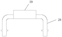
Please refer to fig. 1, fig. 2, fig. 5 and fig. 6. The external heat dissipation assembly 2 comprises a heat conduction box 29 which is arranged in the lower shell 11 and is tightly attached to the first copper pipe 17 and the second copper pipe 18; two ends of the heat conduction box 29 are respectively connected with two fixed tubes 28; one end of the fixed tube 28 is connected with the heat conduction box 29, the other end of the fixed tube passes through the lower shell 11 downwards, the other ends of the two fixed tubes 28 are respectively communicated with one ends of the two liquid guide tubes 21, and the fixed tube 28 and the liquid guide tubes 21 are detachably connected; the fixed pipe 28 is fixedly connected with the bottom wall of the lower shell 11; the other ends of the two liquid guide pipes 21 are respectively connected with the two ends of a spiral cooling pipe 22, wherein one liquid guide pipe 21 is connected with the spiral cooling pipe 22 through a water pump 23. The connection end of the fixing tube 28 and the liquid guide tube 21 is a quick connector, and when the external heat dissipation assembly 2 is not needed, the liquid guide tube 21 can be detached.
The heat conducting box 29 is made of copper alloy material and is used for conducting out heat on the first copper pipe 17 and the second copper pipe 18. The fixed pipe 28 is used for communicating the heat conduction box 29 with the liquid guide pipe 21, the cooling liquid is stored in the spiral cooling pipe 22, and the water pump 23 is used for providing power so that the cooling liquid can circularly flow in the heat conduction box 29, the fixed pipe 28, the liquid guide pipe 21 and the spiral cooling pipe 22, thereby continuously and efficiently dissipating heat.
In order to further improve the cooling effect of the spiral cooling pipe 22, a supporting seat 24 is fixed at the bottom of the spiral cooling pipe 22; a cooling fan 26 is fixed in the supporting seat 24; the air outlet direction of the cooling fan 26 is toward the spiral cooling pipe 22. A vertically arranged freezing pipe 25 is detachably fixed on the support seat 24; the top of the freezing pipe 25 is open; the spiral cooling pipe 22 is spirally wound on the outer side of the freezing pipe 25; the axis of the freezing pipe 25 coincides with the spiral axis of the spiral cooling pipe 22. A top cover 27 is fixed on the top of the spiral cooling pipe 22; the middle part of the top cover 27 is provided with a limiting hole for the freezing pipe 25 to pass through; the upper surface of the bottom of the stay 24 has a fixing groove for receiving the lower end of the freezing pipe 25. The freezing pipe 25 can be used for placing ice blocks or other low-temperature objects, and can effectively improve the cooling efficiency of the spiral cooling pipe 22, so that the overall heat dissipation efficiency is improved, and the normal and stable operation of the notebook computer can be ensured in extreme high-temperature environments. The cooling fan 26 can accelerate the flow rate of air around the spiral cooling pipe 22, and can effectively accelerate the cooling efficiency of the cooling liquid in the spiral cooling pipe 22.
In addition, one side wall of the heat conduction box 29 is provided with a groove 291 matched with the first copper pipe 17 and the second copper pipe 18; the first copper tube 17 and the second copper tube 18 are detachably fitted into the groove 291 and closely attached to the inner wall of the groove 291. The inner wall of the groove 291 is of an arc structure matched with the first copper pipe 17 and the second copper pipe 18, so that the contact area can be increased, and the heat dissipation efficiency is improved.
In order to reduce noise generated by vibration of the cooling fan 26, a damping sleeve 241 is fixed to the bottom of the stay 24.
The notebook computer provided by the invention is made of the casing of the notebook computer.
The shell of the notebook computer and the notebook computer have the following characteristics when in use:
1. according to the shell of the notebook computer and the notebook computer, the lower shell 11 with the dustproof grille 13 is arranged, the back cover 16 with the dustproof net 163 is arranged at the bottom of the lower shell 11, the first copper pipe 17, the second copper pipe 18 and the two cooling fans 19 for conducting heat outwards are arranged inside the lower shell 11, so that the heat inside the shell can be conducted to the cooling fans 19 through the first copper pipe 17 and the second copper pipe 18, and then the heat is blown out along with the gas through the cooling fans 19;
2. in addition, the heat conduction box 29 tightly attached to the first copper pipe 17 and the second copper pipe 18 is arranged, and the heat conduction box 29 is connected with the external spiral cooling pipe 22 through the liquid guide pipe 21, so that the first copper pipe 17 and the second copper pipe 18 can be cooled in an accelerated manner in a liquid cooling mode, and the cooling effect is further improved.
3. Through the bottom installation threaded rod 14 at lower casing 11 to set up at the lower extreme of threaded rod 14 and prop ball 15, thereby can be through the degree of depth of stretching into of adjusting threaded rod 14 in lower casing 11 with the support height and the angle of regulation to casing 11 down, prop ball 15 simultaneously can the adaptability with place the platform stable contact, it is more convenient to use.
The present invention is not limited to the above preferred embodiments, and any modifications, equivalent substitutions and improvements made within the spirit and principle of the present invention should be included in the protection scope of the present invention.
Claims (10)
1. A casing of notebook computer which characterized in that: the method comprises the following steps:
the shell assembly (1) comprises a lower shell (11) and an upper shell (12) which are hinged and fixed with each other; a plurality of threaded rods (14) are fixed at the bottom of the lower shell (11); the lower end of the threaded rod (14) is sleeved with a support ball (15); the two opposite side walls of the lower shell (11) in the length direction are both provided with vent holes, and a dustproof grille (13) is detachably mounted in each vent groove; the lower surface of the lower shell (11) is provided with an opening which is covered with a back cover (16); the back cover (16) is detachably and fixedly connected with the lower shell (11); two cooling fans (19) which respectively correspond to the two dustproof grids (13) are mounted on the side wall of the lower shell (11); a first copper pipe (17) and a second copper pipe (18) which are arranged in parallel are arranged in the lower shell (11); the two ends of the first copper pipe (17) and the second copper pipe (18) respectively extend to the positions of the two cooling fans (19); two dust screens (163) which respectively correspond to the two heat dissipation fans (19) are arranged on the back cover (16);
the external heat dissipation assembly (2) comprises a heat conduction box (29) which is arranged in the lower shell (11) and is tightly attached to the first copper pipe (17) and the second copper pipe (18); two ends of the heat conduction box (29) are respectively connected with two fixed tubes (28); one end of each fixed pipe (28) is connected with the heat conduction box (29), the other end of each fixed pipe penetrates through the lower shell (11) downwards, the other ends of the two fixed pipes (28) are respectively communicated with one ends of the two liquid guide pipes (21), and the fixed pipes (28) are detachably connected with the liquid guide pipes (21); the fixed pipe (28) is fixedly connected with the bottom wall of the lower shell (11); the other ends of the two liquid guide pipes (21) are respectively connected with two ends of a spiral cooling pipe (22), and one of the liquid guide pipes (21) is connected with the spiral cooling pipe (22) through a water pump (23).
2. The notebook computer case of claim 1, wherein: a support seat (24) is fixed at the bottom of the spiral cooling pipe (22); a cooling fan (26) is fixed in the supporting seat (24); the air outlet direction of the cooling fan (26) faces the spiral cooling pipe (22).
3. A housing for a notebook computer, as defined in claim 2, wherein: a vertically arranged freezing pipe (25) is detachably fixed on the support seat (24); the top of the freezing pipe (25) is open;
the spiral cooling pipe (22) is spirally wound on the outer side of the freezing pipe (25); the axial lead of the freezing pipe (25) is superposed with the spiral axial lead of the spiral cooling pipe (22).
4. A case for a notebook computer according to claim 3, wherein: a top cover (27) is fixed at the top of the spiral cooling pipe (22);
the middle part of the top cover (27) is provided with a limiting hole for the freezing pipe (25) to pass through;
the upper surface of the bottom of the stay seat (24) is provided with a fixing groove for accommodating the lower end of the freezing pipe (25).
5. A housing for a notebook computer, as defined in claim 2, wherein: the bottom of the supporting seat (24) is fixedly sleeved with a damping sleeve (241).
6. The notebook computer case of claim 1, wherein: the lower shell (11) is of a cuboid structure; the four corners of the bottom of the lower shell (11) are provided with a threaded hole (112);
the threaded rod (14) is provided with four threaded holes (112) corresponding to the four threaded holes respectively.
7. The notebook computer case of claim 1, wherein: the dustproof grating (13) is internally provided with a plurality of grid plates (131) which are uniformly distributed at intervals along the length direction of the dustproof grating (13);
the edge of the dustproof grille (13) is provided with a plurality of bulges (132) which extend outwards;
the outer surface of the side wall of the lower shell (11) is provided with a concave part matched with the convex part (132); the convex part (132) and the concave part are fixedly connected through bolts.
8. The notebook computer case of claim 1, wherein: a side wall of the heat conduction box (29) is provided with a groove (291) matched with the first copper pipe (17) and the second copper pipe (18);
the first copper pipe (17) and the second copper pipe (18) are detachably embedded into the groove (291) and cling to the inner wall of the groove (291).
9. The notebook computer case of claim 1, wherein: and a plurality of cushion blocks (111) are fixed at the bottom edge of the lower shell (11).
10. A notebook computer, characterized in that: the notebook computer casing is manufactured by adopting the notebook computer casing as claimed in any one of the claims 1 to 9.
Priority Applications (1)
| Application Number | Priority Date | Filing Date | Title |
|---|---|---|---|
| CN202111027346.7A CN113741635A (en) | 2021-09-02 | 2021-09-02 | Notebook computer and shell thereof |
Applications Claiming Priority (1)
| Application Number | Priority Date | Filing Date | Title |
|---|---|---|---|
| CN202111027346.7A CN113741635A (en) | 2021-09-02 | 2021-09-02 | Notebook computer and shell thereof |
Publications (1)
| Publication Number | Publication Date |
|---|---|
| CN113741635A true CN113741635A (en) | 2021-12-03 |
Family
ID=78734970
Family Applications (1)
| Application Number | Title | Priority Date | Filing Date |
|---|---|---|---|
| CN202111027346.7A Pending CN113741635A (en) | 2021-09-02 | 2021-09-02 | Notebook computer and shell thereof |
Country Status (1)
| Country | Link |
|---|---|
| CN (1) | CN113741635A (en) |
Citations (11)
| Publication number | Priority date | Publication date | Assignee | Title |
|---|---|---|---|---|
| TWM244417U (en) * | 2003-10-29 | 2004-09-21 | Tsung-Jr Chen | Improved water tray structure for cooling exchanger |
| US20070217152A1 (en) * | 2006-03-16 | 2007-09-20 | Kloeppel Gregg M | Integrated liquid cooled heatsink system |
| US20110103011A1 (en) * | 2007-12-18 | 2011-05-05 | Koplow Jeffrey P | Heat exchanger device and method for heat removal or transfer |
| CN206639113U (en) * | 2017-04-12 | 2017-11-14 | 姚博远 | A kind of contact water cooling notebook computer base |
| CN206961061U (en) * | 2017-07-17 | 2018-02-02 | 陈子豪 | A kind of cold external radiator for laptop of liquid |
| CN108916562A (en) * | 2018-05-10 | 2018-11-30 | 李志平 | A kind of notebook computer support of adjustable height |
| CN109557988A (en) * | 2018-12-05 | 2019-04-02 | 徐州安鑫智能科技有限公司 | A kind of radiator for laptop |
| CN210666654U (en) * | 2019-10-30 | 2020-06-02 | 江苏吉祥星智能科技有限公司 | Notebook computer mainboard heat dissipation mechanism |
| CN211061984U (en) * | 2019-11-19 | 2020-07-21 | 王辉 | Computer heat abstractor |
| CN111949098A (en) * | 2020-08-11 | 2020-11-17 | 杭州宽福科技有限公司 | Heat dissipation equipment for notebook computer |
| CN112379751A (en) * | 2020-11-13 | 2021-02-19 | 苏州佩秋信息科技有限公司 | Information technology equipment terminal heat dissipation base |
-
2021
- 2021-09-02 CN CN202111027346.7A patent/CN113741635A/en active Pending
Patent Citations (11)
| Publication number | Priority date | Publication date | Assignee | Title |
|---|---|---|---|---|
| TWM244417U (en) * | 2003-10-29 | 2004-09-21 | Tsung-Jr Chen | Improved water tray structure for cooling exchanger |
| US20070217152A1 (en) * | 2006-03-16 | 2007-09-20 | Kloeppel Gregg M | Integrated liquid cooled heatsink system |
| US20110103011A1 (en) * | 2007-12-18 | 2011-05-05 | Koplow Jeffrey P | Heat exchanger device and method for heat removal or transfer |
| CN206639113U (en) * | 2017-04-12 | 2017-11-14 | 姚博远 | A kind of contact water cooling notebook computer base |
| CN206961061U (en) * | 2017-07-17 | 2018-02-02 | 陈子豪 | A kind of cold external radiator for laptop of liquid |
| CN108916562A (en) * | 2018-05-10 | 2018-11-30 | 李志平 | A kind of notebook computer support of adjustable height |
| CN109557988A (en) * | 2018-12-05 | 2019-04-02 | 徐州安鑫智能科技有限公司 | A kind of radiator for laptop |
| CN210666654U (en) * | 2019-10-30 | 2020-06-02 | 江苏吉祥星智能科技有限公司 | Notebook computer mainboard heat dissipation mechanism |
| CN211061984U (en) * | 2019-11-19 | 2020-07-21 | 王辉 | Computer heat abstractor |
| CN111949098A (en) * | 2020-08-11 | 2020-11-17 | 杭州宽福科技有限公司 | Heat dissipation equipment for notebook computer |
| CN112379751A (en) * | 2020-11-13 | 2021-02-19 | 苏州佩秋信息科技有限公司 | Information technology equipment terminal heat dissipation base |
Similar Documents
| Publication | Publication Date | Title |
|---|---|---|
| US7990701B2 (en) | Computer device with low acoustic noise | |
| US9013873B2 (en) | Container data center | |
| US9265181B2 (en) | Heat dissipation apparatus and electronic device using the same | |
| US8395890B2 (en) | All-in-one computer | |
| US7120017B2 (en) | Heat dissipating system of personal computer | |
| US20110122576A1 (en) | Computer | |
| CN107943254A (en) | A kind of portable computer device and its radiating module | |
| US20170153678A1 (en) | Portable information apparatus | |
| US8089761B2 (en) | Computer | |
| US20130148297A1 (en) | Electronic device with air duct | |
| CN113741635A (en) | Notebook computer and shell thereof | |
| US8085536B2 (en) | Computer | |
| CN210324068U (en) | Industrial computer case with good heat dissipation effect | |
| CN218158928U (en) | Shockproof protection structure for computer hard disk | |
| US8154865B2 (en) | Computer including a disk drive, motherboard and fan | |
| US20150138719A1 (en) | Small High Performance Computer Enclosure | |
| CN214011894U (en) | Computer application data storage device | |
| US20140185236A1 (en) | Cooling module and computer enclosure using the same | |
| CN211831688U (en) | Controller heat abstractor | |
| CN209642870U (en) | A kind of network technology set-top box with high-efficient radiating function | |
| CN113985973A (en) | Special explosion-proof computer of high temperature environment | |
| CN111708410A (en) | Heat dissipation device and case | |
| JP2010107657A (en) | Display device | |
| KR100544648B1 (en) | Cooling apparatus for an electronic parts | |
| CN101165356A (en) | Centrifugal fan, heat radiation device possessing the centrifugal fan and electronic device using the heat radiation device |
Legal Events
| Date | Code | Title | Description |
|---|---|---|---|
| PB01 | Publication | ||
| PB01 | Publication | ||
| SE01 | Entry into force of request for substantive examination | ||
| SE01 | Entry into force of request for substantive examination |