CN113729456B - Spliced indoor screen convenient to maintain and splicing method thereof - Google Patents
Spliced indoor screen convenient to maintain and splicing method thereof Download PDFInfo
- Publication number
- CN113729456B CN113729456B CN202111124653.7A CN202111124653A CN113729456B CN 113729456 B CN113729456 B CN 113729456B CN 202111124653 A CN202111124653 A CN 202111124653A CN 113729456 B CN113729456 B CN 113729456B
- Authority
- CN
- China
- Prior art keywords
- screen main
- positioning
- plate
- auxiliary
- top plate
- Prior art date
- Legal status (The legal status is an assumption and is not a legal conclusion. Google has not performed a legal analysis and makes no representation as to the accuracy of the status listed.)
- Active
Links
Images


Classifications
-
- A—HUMAN NECESSITIES
- A47—FURNITURE; DOMESTIC ARTICLES OR APPLIANCES; COFFEE MILLS; SPICE MILLS; SUCTION CLEANERS IN GENERAL
- A47G—HOUSEHOLD OR TABLE EQUIPMENT
- A47G5/00—Screens; Draught-deflectors
Abstract
The invention relates to the field of indoor design, in particular to a splicing type indoor screen convenient to maintain and a splicing method thereof. The screen main boards are rectangular arrayed on the ground, and positioning blocks are arranged on the opposite side surfaces between the adjacent screen main boards. The side surfaces of the two sides of the auxiliary plate arranged between the adjacent screen main plates are symmetrically provided with connecting blocks, and the positioning pins on the connecting blocks are detachably arranged in the positioning holes of the positioning blocks. The limiting mechanisms corresponding to the positioning blocks are respectively arranged on the side surfaces of the screen main board and consist of a top plate and a mounting block, the mounting block is arranged on the side surface of the screen main board, and the ejector rods on the top plate are embedded in the sliding grooves on the surface of the mounting block in a sliding way. When the folding screen is operated, the side face of the auxiliary plate and the top end of the connecting block can be propped by the top plate, so that the positioning pin is prevented from being separated from the positioning hole in the use process, the connection stability of the screen main plate and the auxiliary plate is enhanced, and the screen main plate and the auxiliary plate are prevented from being loosened and separated in the use process.
Description
Technical Field
The invention relates to the field of indoor design, in particular to a splicing type indoor screen convenient to maintain and a splicing method thereof.
Background
The screen is a piece of furniture for keeping out wind in the traditional building in China, namely 'screen wind is also'; the screen is used as an important component of the traditional furniture and has a long history; the screen is generally Chen Sheyu indoor significant position, play the effect such as separate, beautify, keep out the wind, coordinate, it reflects with classical furniture each other, bring out the best in each other, an integrated body, become the inseparable whole of chinese style home decoration, and present a harmonious beauty, quiet beauty, the screen is mostly formed by interconnecting a plurality of screen boards, however current screen connection structure is too loaded down with trivial details complicacy, if certain screen board damages in the use and needs to be changed, the operation is very inconvenient.
Disclosure of Invention
Aiming at the defects brought by the background technology, the invention provides a splicing type indoor screen convenient to maintain and a splicing method thereof.
The invention adopts the following technical scheme that:
the screen main board is provided with a plurality of blocks, the screen main boards are arranged on the ground in a rectangular array mode, positioning blocks are arranged on the opposite side surfaces between the adjacent screen main boards, and positioning holes penetrate through the positioning blocks;
the auxiliary plate is provided with a plurality of auxiliary plates which are respectively arranged between the adjacent screen main plates, the side surfaces of the two sides of each auxiliary plate are symmetrically provided with connecting blocks, positioning pins are arranged on the connecting blocks, the positioning pins are respectively detachably arranged in the positioning holes, and the diameter size of each positioning pin is smaller than that of each positioning hole;
the limiting mechanism is provided with a plurality of limiting mechanisms, the limiting mechanisms are respectively arranged on the side faces of the screen main board, the limiting mechanisms correspond to the positioning blocks, the limiting mechanisms are located at positions higher than the positioning blocks, each limiting mechanism comprises a top plate and an installation block, the installation blocks are connected to the side faces of the screen main board, the surfaces of the installation blocks are provided with inwards-recessed sliding grooves, one side, close to the installation blocks, of each top plate is provided with an ejector rod, the ejector rods are embedded in the sliding grooves in a sliding mode and are used for abutting against the side faces of the auxiliary boards, when the top plates abut against the auxiliary boards, the bottom ends of the top plates are tightly attached to the top ends of the connecting blocks, the front side faces and the rear side faces of the top plates are flush with the front surface and the rear surface of the auxiliary boards, one end, close to the installation blocks, of each ejector rod is internally provided with a connecting groove, a spring is arranged between each connecting groove and each sliding groove, and when the top plates move to be close to the installation blocks, the springs are compressed by the top plates.
As a further improvement, a mounting groove is arranged on the side surface of the screen main plate, the mounting block is rotatably arranged in the mounting groove, the top plate is of a cuboid structure, when the mounting block drives the top plate to rotate to the horizontal arrangement of the top plate, the front side surface and the rear side surface of the top plate both extend out of the front surface and the rear surface of the auxiliary plate, and when the top plate is vertically arranged, the front side surface and the rear side surface of the top plate are level with the front surface and the rear surface of the auxiliary plate.
As a further improvement, the mounting block is detachably embedded in the mounting groove.
As a further improvement, a first magnetic block is arranged on the inner wall of the mounting groove, a second magnetic block is arranged on the surface of the mounting block, the second magnetic block and the first magnetic block are attracted magnetically, and when the first magnetic block and the second magnetic block are overlapped and correspond to each other, the top plate is vertically arranged on the side face of the screen main plate.
A splicing method of a splicing type indoor screen convenient to maintain is characterized by comprising the following steps:
firstly, downwards moving an auxiliary plate and a positioning pin to be embedded into a positioning hole of a screen main plate, and pushing a top plate on the screen main plate to two sides by the positioning pin in the downwards moving process of the auxiliary plate and the positioning pin; secondly, the top plate drives the ejector rod to move along the sliding groove and approach the mounting block, and the top plate compresses the spring at the moment; thirdly, after the positioning pin is completely inserted into the positioning hole, the top plate resets under the action of the elastic restoring force of the spring and props against the side surface of the auxiliary plate and the top end of the connecting block for positioning; fourthly, because the diameter size of the positioning pin is smaller than that of the positioning hole, when a walking person collides with the screen main board carelessly, the screen main board deflects to enable the positioning pin and the positioning hole to move relatively, the auxiliary board pushes the top board to enable the top board to move the compression spring, and the compression deformation of the spring can buffer and absorb the impact force on the screen main board and the auxiliary board.
From the above description of the structure of the present invention, compared with the prior art, the present invention has the following advantages: the screen comprises a screen main board, an auxiliary board and a limiting mechanism. The screen main boards are arranged on the ground in a rectangular array, and positioning blocks are arranged on the opposite side surfaces between the adjacent screen main boards. The side surfaces of two sides of the auxiliary plate arranged between the adjacent screen main plates are symmetrically provided with connecting blocks, and the positioning pins on the connecting blocks are detachably arranged in the positioning holes of the positioning blocks. The limiting mechanisms corresponding to the positioning blocks are respectively arranged on the side surfaces of the screen main boards and consist of top boards and mounting blocks, the mounting blocks are arranged on the side surfaces of the screen main boards, and ejector rods on the top boards are slidably embedded in sliding grooves in the surfaces of the mounting blocks. When the folding screen is operated, the side face of the auxiliary plate and the top end of the connecting block can be propped by the top plate, so that the positioning pin is prevented from being separated from the positioning hole in the use process, the connection stability of the screen main plate and the auxiliary plate is enhanced, and the screen main plate and the auxiliary plate are prevented from being loosened and separated in the use process.
Drawings
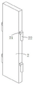
Fig. 1 is a schematic perspective view of the present invention.
Fig. 2 is a schematic perspective view of the sub-plate.
Fig. 3 is a schematic perspective view of a screen main board.
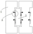
Fig. 4 is a schematic sectional structure view of the secondary plate and the screen main plate.
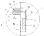
Fig. 5 is a schematic structural diagram of a in fig. 4.
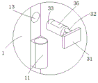
Fig. 6 is a schematic structural view of the top plate after being rotated to a transverse arrangement.
Fig. 7 is a schematic perspective view of the mounting block separated from the screen main board.
Fig. 8 is a schematic structural diagram of B in fig. 7.
Detailed Description
The following describes embodiments of the present invention with reference to the drawings.
As shown in attached figures 1 and 3, the splicing type indoor screen convenient for maintenance comprises a screen main board 1, an auxiliary board 2 and a limiting mechanism 3.
As shown in fig. 1, 2 and 3, the screen main board 1 is provided with a plurality of blocks, the plurality of screen main boards 1 are arranged on the ground in a rectangular array manner, positioning blocks 11 are respectively arranged on opposite sides between adjacent screen main boards 1, positioning holes 12 are respectively penetrated through the positioning blocks 11, the plurality of auxiliary boards 2 are respectively arranged between the adjacent screen main boards 1, the side faces of both sides of the auxiliary board 2 are symmetrically provided with connecting blocks 21, the connecting blocks 21 are provided with positioning pins 22, the positioning pins 22 are respectively and detachably arranged in the positioning holes 12, when in operation, the positioning pins 22 are inserted into the positioning holes 12 from top to bottom to realize the connection of the screen main boards 1 and the auxiliary boards 2, the regularly arranged screen main boards 1 can be connected together through the auxiliary boards 2, and the screen main boards 1 and the auxiliary boards 2 can rotate, so that the screen main boards 1 can be folded and adjusted according to the field size, and the practicability of the screen is improved.
As shown in fig. 3, 4 and 5, the limiting mechanisms 3 are provided with a plurality of limiting mechanisms 3, the limiting mechanisms 3 are respectively disposed on the side surfaces of the screen main board 1, the limiting mechanisms 3 correspond to the positioning blocks 11, the height of the limiting mechanisms 3 is higher than that of the positioning blocks 11, the limiting mechanisms 3 include a top plate 31 and a mounting block 33, the mounting block 33 is connected to the side surface of the screen main board 1, the surface of the mounting block 33 is provided with an inward recessed sliding groove 331, one side of the top plate 31 close to the mounting block 33 is provided with a top rod 32, the top rod 32 is slidably embedded in the sliding groove 331, after the positioning pin 22 is inserted into the positioning hole 12 from top to bottom, the top plate 31 is abutted against the side surface of the secondary board 2, at this time, the bottom end of the top plate 31 is abutted against the top end of the connecting block 21, the limiting effect of the top plate 31 on the connecting block 21 and the positioning pin 22 is utilized to prevent the positioning pin 22 from being separated from the positioning hole 12 in the using process, so as to enhance the connecting stability of the screen main board 1 and the secondary board 2, and to prevent the screen main board 1 and the secondary board 2 from being loosened and separated in the using process. When a certain screen main board 1 or auxiliary board 2 is damaged, the auxiliary board 2 and the positioning pin 22 can be moved upwards to be separated from the screen main board 1 and the positioning hole 12 only by moving away the top board 31 on the connecting block 21 and the positioning pin 22, so that the screen main board 1 or the auxiliary board 2 can be replaced in time and independently, and the positioning pin 22, the connecting block 21, the top board 31, the ejector rod 32, the positioning block 11, the mounting block 33 and the like can be made of materials the same as the screen main board 1 or the auxiliary board 2, so that the uniformity of the screen is enhanced, and the visual effect and the integral aesthetic degree of the screen are improved. And the front and back two side surfaces of the top plate 31 are level with the front and back surfaces of the auxiliary plate 2, so as to avoid being obtrusive, and ensure that the whole screen is smoother and more beautiful.
As shown in fig. 4 and 5, a connecting groove 321 is provided in one end of the top bar 32 close to the mounting block 33, a spring 34 is provided between the connecting groove 321 and the sliding groove 331, in the process of moving the secondary plate 2 and the positioning pin 22 downward to insert the positioning pin 22 into the positioning hole 12, the positioning pin 22 pushes the top plate 31 on the screen main plate 1 to both sides, so that the top plate 31 drives the top bar 32 to move along the sliding groove 331 to close to the mounting block 33, at this time, the top plate 31 compresses the spring 34 to give way for the positioning pin 22, so that the positioning pin 22 can be smoothly inserted into the positioning hole 12, after the positioning pin 22 is completely inserted into the positioning hole 12, the top plate 31 is reset under the elastic restoring force of the spring 34 to push against the side surface of the secondary plate 2 and the top end of the connecting block 21, thereby preventing the positioning pin 22 from being separated from the positioning hole 12 in the using process, enhancing the connection stability of the screen main plate 1 and the secondary plate 2, and preventing the main plate 1 and the secondary plate 2 from being loosened and separated in the using process. And because the diameter size of the locating pin 22 is smaller than the diameter size of the locating hole 12, when a walking person collides the screen main board 1 carelessly, the screen main board 1 deflects, so that the locating pin 22 and the locating hole 12 move relatively, at the moment, the auxiliary board 2 pushes the top board 31, so that the top board 31 moves the compression spring 34, and the compression deformation of the spring 34 can buffer and absorb the impact force applied to the screen main board 1 and the auxiliary board 2, thereby reducing the risk that the screen main board 1 and the auxiliary board 2 are stressed to generate large deflection, and simultaneously reducing the risk that the screen main board 1 is stressed to topple over, thereby ensuring the integrity of the screen main board 1 and the auxiliary board 2, and prolonging the service life of the screen main board 1 and the auxiliary board 2.
As shown in fig. 6, 7 and 8, the side surface of the screen main board 1 is provided with a mounting groove 13, the mounting block 33 is rotatably disposed in the mounting groove 13, and the top plate 31 is of a rectangular structure, when the screen main board 1 or the secondary board 2 needs to be replaced separately, so that the secondary board 2 is separated from the screen main board 1, the ejector rod 32 and the top plate 31 can be held to rotate, and the top plate 31 on the mounting block 33 is rotated to be transversely disposed, at this time, the front and rear side surfaces of the top plate 31 both extend out of the front and rear surfaces of the secondary board 2, and then the top plate 31 can be manually pushed to both sides, so that the top plate 31 is away from the secondary board 2 and the positioning pin 22, so as to facilitate the separation of the secondary board 2 and the screen main board 1, wherein the rotation of the top plate 31 can facilitate the pushing of the top plate 31 to accelerate the dismounting efficiency of the secondary board 2 and the screen main board 1, and when the top plate 31 is vertically disposed, the front and rear side surfaces of the top plate 31 are flush with the front and rear surfaces of the secondary board 2, so as to avoid being abrupt, and make the whole smoother and more beautiful. Further, the mounting block 33 is detachably embedded in the mounting groove 13, specifically, a first magnetic block 35 is arranged on the inner wall of the mounting groove 13, a second magnetic block 36 is arranged on the surface of the mounting block 33, the second magnetic block 36 magnetically attracts the first magnetic block 35, and when the first magnetic block 35 is superposed and corresponds to the second magnetic block 36, the top plate 31 is vertically arranged on the side surface of the screen main plate 1, and the risk of rotation of the top plate 31 and the mounting block 33 in the using process is reduced by utilizing the magnetic attraction between the second magnetic block 36 and the first magnetic block 35, so that the front side surface and the rear side surface of the top plate 31 can be stably leveled with the front surface and the rear surface of the subplate 2, the whole screen is more flat and beautiful, if the limiting mechanism 3 is damaged in the using process, the top rod 32 and the top plate 31 can be held, the mounting block 33 can be pulled out of the mounting groove 13 by overcoming the magnetic attraction, the convenience is brought for individual replacement and quick limiting mechanism 3, and the service life of the screen is prolonged.
During assembly, the auxiliary plate 2 and the positioning pin 22 are moved downwards to be embedded into the positioning hole 12 of the screen main plate 1, and in the process of moving downwards of the auxiliary plate 2 and the positioning pin 22, the positioning pin 22 pushes the top plate 31 on the screen main plate 1 towards two sides, so that the top plate 31 drives the ejector rod 32 to move along the sliding groove 331 to be close to the mounting block 33, at this time, the top plate 31 compresses the spring 34 to give way for the positioning pin 22, so that the positioning pin 22 can be smoothly inserted into the positioning hole 12, after the positioning pin 22 is completely inserted into the positioning hole 12, the top plate 31 is reset under the elastic restoring force of the spring 34 to prop against the side surface of the auxiliary plate 2 and the top end of the connecting block 21, so that the positioning pin 22 is prevented from being separated from the positioning hole 12 in the use process, the connection stability of the screen main plate 1 and the auxiliary plate 2 is enhanced, and the screen main plate 1 and the auxiliary plate 2 are prevented from being loosened and separated in the use process. And because the diameter size of the locating pin 22 is smaller than the diameter size of the locating hole 12, when a walking person collides the screen main board 1 carelessly, the screen main board 1 deflects, so that the locating pin 22 and the locating hole 12 move relatively, at the moment, the auxiliary board 2 pushes the top board 31, so that the top board 31 moves the compression spring 34, and the compression deformation of the spring 34 can buffer and absorb the impact force applied to the screen main board 1 and the auxiliary board 2, thereby reducing the risk that the screen main board 1 and the auxiliary board 2 are stressed to generate large deflection, and simultaneously reducing the risk that the screen main board 1 is stressed to topple over, thereby ensuring the integrity of the screen main board 1 and the auxiliary board 2, and prolonging the service life of the screen main board 1 and the auxiliary board 2. When a certain screen main board 1 or auxiliary board 2 is damaged and needs to be replaced, the ejector rod 32 and the top board 31 can be held to rotate, the top board 31 on the mounting block 33 is rotated to be transversely arranged, at the moment, the front side surface and the rear side surface of the top board 31 both extend out of the front surface and the rear surface of the auxiliary board 2, then the top board 31 can be pushed and pressed towards the two sides manually, the top board 31 is far away from the auxiliary board 2 and the positioning pins 22, so that the auxiliary board 2 and the screen main board 1 can be separated conveniently, wherein the top board 31 can be rotated to be beneficial to pushing and pressing the top board 31, and the dismounting efficiency and the replacing efficiency of the auxiliary board 2 and the screen main board 1 are accelerated.
A splicing method of a splicing type indoor screen convenient to maintain is characterized by comprising the following steps:
firstly, during assembly, the auxiliary plate 2 and the positioning pin 22 are moved downwards to be embedded into the positioning hole 12 of the screen main plate 1, and the positioning pin 22 pushes the top plate 31 on the screen main plate 1 to two sides in the process of moving the auxiliary plate 2 and the positioning pin 22 downwards;
secondly, the top plate 31 drives the top rod 32 to move along the sliding groove 331 and approach the mounting block 33, and at this time, the top plate 31 compresses the spring 34 to give way for the positioning pin 22, so that the positioning pin 22 can be smoothly inserted into the positioning hole 12;
thirdly, after the positioning pin 22 is completely inserted into the positioning hole 12, the top plate 31 is reset under the action of the elastic restoring force of the spring 34 and props against the side surface of the secondary plate 2 and the top end of the connecting block 21, so that the positioning pin 22 is prevented from being separated from the positioning hole 12 in the using process, the connection stability of the screen main plate 1 and the secondary plate 2 is enhanced, and the screen main plate 1 and the secondary plate 2 are prevented from being loosened and separated in the using process;
fourthly, because the diameter size of the positioning pin 22 is smaller than that of the positioning hole 12, when a walking person collides with the screen main board 1 carelessly, the screen main board 1 deflects to enable the positioning pin 22 and the positioning hole 12 to move relatively, at the moment, the auxiliary board 2 pushes the top board 31 to enable the top board 31 to move the compression spring 34, and the compression deformation of the spring 34 can buffer and absorb the impact force on the screen main board 1 and the auxiliary board 2, so that the risk of large deflection caused by the stress on the screen main board 1 and the auxiliary board 2 is reduced, and the risk of toppling over of the screen main board 1 caused by the stress can be reduced, thereby ensuring the integrity of the screen main board 1 and the auxiliary board 2, and prolonging the service life of the screen main board 1 and the auxiliary board 2.
The above description is only an embodiment of the present invention, but the design concept of the present invention is not limited thereto, and any insubstantial modifications made by using the design concept should fall within the scope of infringing the present invention.
Claims (5)
1. The utility model provides an indoor screen of concatenation formula convenient to maintenance which characterized in that, including:
the screen main boards are provided with a plurality of blocks, the screen main boards are arranged on the ground in a rectangular array mode, positioning blocks are arranged on the opposite side surfaces between the adjacent screen main boards, and positioning holes are penetrated through the positioning blocks;
the auxiliary plate is provided with a plurality of auxiliary plates which are respectively arranged between the adjacent screen main plates, the side surfaces of the two sides of each auxiliary plate are symmetrically provided with connecting blocks, positioning pins are arranged on the connecting blocks, the positioning pins are respectively detachably arranged in the positioning holes, and the diameter of each positioning pin is smaller than that of each positioning hole;
the limiting mechanism is provided with a plurality of limiting mechanisms, the limiting mechanisms are respectively arranged on the side faces of the screen main board, the limiting mechanisms correspond to the positioning blocks, the limiting mechanisms are located at positions higher than the positioning blocks, each limiting mechanism comprises a top plate and an installation block, the installation blocks are connected to the side faces of the screen main board, the surfaces of the installation blocks are provided with inwards-recessed sliding grooves, one side, close to the installation blocks, of each top plate is provided with an ejector rod, the ejector rods are embedded in the sliding grooves in a sliding mode and are used for abutting against the side faces of the auxiliary boards, when the top plates abut against the auxiliary boards, the bottom ends of the top plates are tightly attached to the top ends of the connecting blocks, the front side faces and the rear side faces of the top plates are flush with the front surface and the rear surface of the auxiliary boards, one end, close to the installation blocks, of each ejector rod is internally provided with a connecting groove, a spring is arranged between each connecting groove and each sliding groove, and when the top plates move to be close to the installation blocks, the springs are compressed by the top plates.
2. The splicing type indoor screen convenient for maintenance as claimed in claim 1, wherein: the side surface of the screen main plate is provided with a mounting groove, the mounting block is rotatably arranged in the mounting groove, the top plate is of a cuboid structure, when the mounting block drives the top plate to rotate to the transverse arrangement of the top plate, the front side surface and the rear side surface of the top plate both extend out of the front surface and the rear surface of the auxiliary plate, and when the top plate is vertically arranged, the front side surface and the rear side surface of the top plate are level with the front surface and the rear surface of the auxiliary plate.
3. A splicing type indoor screen convenient for maintenance as claimed in claim 2, wherein: the installation block is detachably embedded in the installation groove.
4. A splicing type indoor screen convenient for maintenance as claimed in claim 3, wherein: the inner wall of the mounting groove is provided with a first magnetic block, the surface of the mounting block is provided with a second magnetic block, the second magnetic block and the first magnetic block are attracted magnetically, and when the first magnetic block and the second magnetic block are superposed and correspond to each other, the top plate is vertically arranged on the side face of the screen main plate.
5. The method for splicing an indoor screen which is convenient to maintain as claimed in any one of claims 1 to 4, is characterized by comprising the following steps:
firstly, downwards moving an auxiliary plate and a positioning pin to be embedded into a positioning hole of a screen main plate, and pushing a top plate on the screen main plate to two sides by the positioning pin in the downwards moving process of the auxiliary plate and the positioning pin;
secondly, the top plate drives the ejector rod to move along the sliding groove and close to the mounting block, and the top plate compresses the spring at the moment;
thirdly, after the positioning pin is completely inserted into the positioning hole, the top plate resets under the action of the elastic restoring force of the spring and props against the side surface of the auxiliary plate and the top end of the connecting block for positioning;
fourthly, because the diameter size of the positioning pin is smaller than that of the positioning hole, when a walking person collides with the screen main board carelessly, the screen main board deflects to enable the positioning pin and the positioning hole to move relatively, the auxiliary board pushes the top board to enable the top board to move the compression spring, and the compression deformation of the spring can buffer and absorb the impact force on the screen main board and the auxiliary board.
Priority Applications (1)
| Application Number | Priority Date | Filing Date | Title |
|---|---|---|---|
| CN202111124653.7A CN113729456B (en) | 2021-09-25 | 2021-09-25 | Spliced indoor screen convenient to maintain and splicing method thereof |
Applications Claiming Priority (1)
| Application Number | Priority Date | Filing Date | Title |
|---|---|---|---|
| CN202111124653.7A CN113729456B (en) | 2021-09-25 | 2021-09-25 | Spliced indoor screen convenient to maintain and splicing method thereof |
Publications (2)
| Publication Number | Publication Date |
|---|---|
| CN113729456A CN113729456A (en) | 2021-12-03 |
| CN113729456B true CN113729456B (en) | 2023-02-28 |
Family
ID=78740957
Family Applications (1)
| Application Number | Title | Priority Date | Filing Date |
|---|---|---|---|
| CN202111124653.7A Active CN113729456B (en) | 2021-09-25 | 2021-09-25 | Spliced indoor screen convenient to maintain and splicing method thereof |
Country Status (1)
| Country | Link |
|---|---|
| CN (1) | CN113729456B (en) |
Citations (7)
| Publication number | Priority date | Publication date | Assignee | Title |
|---|---|---|---|---|
| US6390173B1 (en) * | 1997-11-26 | 2002-05-21 | Paul J. Story, Jr. | Method of making a screen frame |
| JP2003119936A (en) * | 2001-10-12 | 2003-04-23 | Kokuyo Co Ltd | Screen |
| CN208281302U (en) * | 2018-02-12 | 2018-12-25 | Hni香港有限公司 | A kind of screen connection weights-hoist |
| CN210342368U (en) * | 2019-06-11 | 2020-04-17 | 广东森景建设有限公司 | Movable combined decorative curtain wall |
| CN211229004U (en) * | 2019-10-30 | 2020-08-11 | 鹿景园林建设集团有限公司 | Wall body module convenient to make construction recovery usefulness |
| CN111828783A (en) * | 2020-06-19 | 2020-10-27 | 杭州恒领科技有限公司 | Automobile exhaust remote alarm system based on Internet of vehicles |
| CN212478217U (en) * | 2020-05-08 | 2021-02-05 | 深圳市洹源建设有限公司 | Bilateral joint formula equipment curtain wall construction of architectural decoration glass curtain wall |
Family Cites Families (1)
| Publication number | Priority date | Publication date | Assignee | Title |
|---|---|---|---|---|
| EP2449599B1 (en) * | 2009-07-02 | 2018-08-15 | SolarCity Corporation | Apparatus for leveling photovoltaic arrays |
-
2021
- 2021-09-25 CN CN202111124653.7A patent/CN113729456B/en active Active
Patent Citations (7)
| Publication number | Priority date | Publication date | Assignee | Title |
|---|---|---|---|---|
| US6390173B1 (en) * | 1997-11-26 | 2002-05-21 | Paul J. Story, Jr. | Method of making a screen frame |
| JP2003119936A (en) * | 2001-10-12 | 2003-04-23 | Kokuyo Co Ltd | Screen |
| CN208281302U (en) * | 2018-02-12 | 2018-12-25 | Hni香港有限公司 | A kind of screen connection weights-hoist |
| CN210342368U (en) * | 2019-06-11 | 2020-04-17 | 广东森景建设有限公司 | Movable combined decorative curtain wall |
| CN211229004U (en) * | 2019-10-30 | 2020-08-11 | 鹿景园林建设集团有限公司 | Wall body module convenient to make construction recovery usefulness |
| CN212478217U (en) * | 2020-05-08 | 2021-02-05 | 深圳市洹源建设有限公司 | Bilateral joint formula equipment curtain wall construction of architectural decoration glass curtain wall |
| CN111828783A (en) * | 2020-06-19 | 2020-10-27 | 杭州恒领科技有限公司 | Automobile exhaust remote alarm system based on Internet of vehicles |
Also Published As
| Publication number | Publication date |
|---|---|
| CN113729456A (en) | 2021-12-03 |
Similar Documents
| Publication | Publication Date | Title |
|---|---|---|
| CN208184148U (en) | A kind of modular flooring with elastic card connector | |
| CN113729456B (en) | Spliced indoor screen convenient to maintain and splicing method thereof | |
| CN216276640U (en) | 3D prints assembled mounting structure of wooden design wall | |
| CN213897506U (en) | Supporting beam for assembled steel structure building | |
| WO2021128681A1 (en) | Magnetic building block | |
| CN211795395U (en) | Stool capable of being packaged in flat plate and convenient to disassemble and assemble | |
| CN206458678U (en) | A kind of plate support of glass partition | |
| CN207613505U (en) | A kind of bed side of wood bed | |
| CN219762741U (en) | Extension type spliced table | |
| CN220795936U (en) | Self-help number calling machine | |
| CN205053363U (en) | Embedded portable buckle device | |
| CN215253878U (en) | Light steel keel gypsum board suspended ceiling | |
| CN218571700U (en) | Desktop mounting structure of outdoor table | |
| CN109998269A (en) | Conference table with display board | |
| CN215094287U (en) | Adjustable support for assembling wood box | |
| CN218343146U (en) | Movable white board | |
| CN209807849U (en) | Interior decoration screen | |
| CN216871705U (en) | Outdoor combined mutual inductor | |
| CN217081002U (en) | Adjustable panel for assembling furniture | |
| CN219213437U (en) | Recoverable interior decoration splice plate | |
| CN111287361B (en) | Aluminum plate curtain wall structure | |
| CN214037762U (en) | High-voltage energy-saving equipment | |
| CN210930160U (en) | Pin-connected panel conference table convenient to transport | |
| CN216340602U (en) | Splice plate for building construction | |
| CN220001134U (en) | Office table capable of being used on two sides |
Legal Events
| Date | Code | Title | Description |
|---|---|---|---|
| PB01 | Publication | ||
| PB01 | Publication | ||
| SE01 | Entry into force of request for substantive examination | ||
| SE01 | Entry into force of request for substantive examination | ||
| GR01 | Patent grant | ||
| GR01 | Patent grant |