CN113726065A - Integrated shell motor range extender with rear auxiliary support - Google Patents
Integrated shell motor range extender with rear auxiliary support Download PDFInfo
- Publication number
- CN113726065A CN113726065A CN202110900006.4A CN202110900006A CN113726065A CN 113726065 A CN113726065 A CN 113726065A CN 202110900006 A CN202110900006 A CN 202110900006A CN 113726065 A CN113726065 A CN 113726065A
- Authority
- CN
- China
- Prior art keywords
- integrated
- auxiliary support
- shell
- integrated shell
- fixedly connected
- Prior art date
- Legal status (The legal status is an assumption and is not a legal conclusion. Google has not performed a legal analysis and makes no representation as to the accuracy of the status listed.)
- Pending
Links
- 239000004606 Fillers/Extenders Substances 0.000 title claims abstract description 21
- 230000005540 biological transmission Effects 0.000 claims description 3
- 238000000034 method Methods 0.000 claims description 2
- 239000007858 starting material Substances 0.000 abstract description 11
- 230000010354 integration Effects 0.000 abstract description 3
- 230000006872 improvement Effects 0.000 description 4
- 230000009467 reduction Effects 0.000 description 3
- 208000019901 Anxiety disease Diseases 0.000 description 2
- 230000004075 alteration Effects 0.000 description 2
- 230000036506 anxiety Effects 0.000 description 2
- 238000010586 diagram Methods 0.000 description 2
- 238000012986 modification Methods 0.000 description 2
- 230000004048 modification Effects 0.000 description 2
- 230000009471 action Effects 0.000 description 1
- 230000000694 effects Effects 0.000 description 1
- 230000005611 electricity Effects 0.000 description 1
- 238000004134 energy conservation Methods 0.000 description 1
- 238000005516 engineering process Methods 0.000 description 1
- 230000007613 environmental effect Effects 0.000 description 1
- 238000004904 shortening Methods 0.000 description 1
Images

Classifications
-
- H—ELECTRICITY
- H02—GENERATION; CONVERSION OR DISTRIBUTION OF ELECTRIC POWER
- H02K—DYNAMO-ELECTRIC MACHINES
- H02K5/00—Casings; Enclosures; Supports
- H02K5/04—Casings or enclosures characterised by the shape, form or construction thereof
-
- B—PERFORMING OPERATIONS; TRANSPORTING
- B60—VEHICLES IN GENERAL
- B60L—PROPULSION OF ELECTRICALLY-PROPELLED VEHICLES; SUPPLYING ELECTRIC POWER FOR AUXILIARY EQUIPMENT OF ELECTRICALLY-PROPELLED VEHICLES; ELECTRODYNAMIC BRAKE SYSTEMS FOR VEHICLES IN GENERAL; MAGNETIC SUSPENSION OR LEVITATION FOR VEHICLES; MONITORING OPERATING VARIABLES OF ELECTRICALLY-PROPELLED VEHICLES; ELECTRIC SAFETY DEVICES FOR ELECTRICALLY-PROPELLED VEHICLES
- B60L50/00—Electric propulsion with power supplied within the vehicle
- B60L50/50—Electric propulsion with power supplied within the vehicle using propulsion power supplied by batteries or fuel cells
- B60L50/60—Electric propulsion with power supplied within the vehicle using propulsion power supplied by batteries or fuel cells using power supplied by batteries
- B60L50/61—Electric propulsion with power supplied within the vehicle using propulsion power supplied by batteries or fuel cells using power supplied by batteries by batteries charged by engine-driven generators, e.g. series hybrid electric vehicles
- B60L50/62—Electric propulsion with power supplied within the vehicle using propulsion power supplied by batteries or fuel cells using power supplied by batteries by batteries charged by engine-driven generators, e.g. series hybrid electric vehicles charged by low-power generators primarily intended to support the batteries, e.g. range extenders
-
- F—MECHANICAL ENGINEERING; LIGHTING; HEATING; WEAPONS; BLASTING
- F02—COMBUSTION ENGINES; HOT-GAS OR COMBUSTION-PRODUCT ENGINE PLANTS
- F02B—INTERNAL-COMBUSTION PISTON ENGINES; COMBUSTION ENGINES IN GENERAL
- F02B63/00—Adaptations of engines for driving pumps, hand-held tools or electric generators; Portable combinations of engines with engine-driven devices
- F02B63/04—Adaptations of engines for driving pumps, hand-held tools or electric generators; Portable combinations of engines with engine-driven devices for electric generators
-
- H—ELECTRICITY
- H02—GENERATION; CONVERSION OR DISTRIBUTION OF ELECTRIC POWER
- H02K—DYNAMO-ELECTRIC MACHINES
- H02K1/00—Details of the magnetic circuit
- H02K1/06—Details of the magnetic circuit characterised by the shape, form or construction
- H02K1/22—Rotating parts of the magnetic circuit
- H02K1/28—Means for mounting or fastening rotating magnetic parts on to, or to, the rotor structures
- H02K1/30—Means for mounting or fastening rotating magnetic parts on to, or to, the rotor structures using intermediate parts, e.g. spiders
-
- H—ELECTRICITY
- H02—GENERATION; CONVERSION OR DISTRIBUTION OF ELECTRIC POWER
- H02K—DYNAMO-ELECTRIC MACHINES
- H02K11/00—Structural association of dynamo-electric machines with electric components or with devices for shielding, monitoring or protection
- H02K11/20—Structural association of dynamo-electric machines with electric components or with devices for shielding, monitoring or protection for measuring, monitoring, testing, protecting or switching
- H02K11/21—Devices for sensing speed or position, or actuated thereby
- H02K11/215—Magnetic effect devices, e.g. Hall-effect or magneto-resistive elements
-
- H—ELECTRICITY
- H02—GENERATION; CONVERSION OR DISTRIBUTION OF ELECTRIC POWER
- H02K—DYNAMO-ELECTRIC MACHINES
- H02K7/00—Arrangements for handling mechanical energy structurally associated with dynamo-electric machines, e.g. structural association with mechanical driving motors or auxiliary dynamo-electric machines
- H02K7/02—Additional mass for increasing inertia, e.g. flywheels
- H02K7/025—Additional mass for increasing inertia, e.g. flywheels for power storage
-
- H—ELECTRICITY
- H02—GENERATION; CONVERSION OR DISTRIBUTION OF ELECTRIC POWER
- H02K—DYNAMO-ELECTRIC MACHINES
- H02K7/00—Arrangements for handling mechanical energy structurally associated with dynamo-electric machines, e.g. structural association with mechanical driving motors or auxiliary dynamo-electric machines
- H02K7/18—Structural association of electric generators with mechanical driving motors, e.g. with turbines
- H02K7/1807—Rotary generators
-
- Y—GENERAL TAGGING OF NEW TECHNOLOGICAL DEVELOPMENTS; GENERAL TAGGING OF CROSS-SECTIONAL TECHNOLOGIES SPANNING OVER SEVERAL SECTIONS OF THE IPC; TECHNICAL SUBJECTS COVERED BY FORMER USPC CROSS-REFERENCE ART COLLECTIONS [XRACs] AND DIGESTS
- Y02—TECHNOLOGIES OR APPLICATIONS FOR MITIGATION OR ADAPTATION AGAINST CLIMATE CHANGE
- Y02E—REDUCTION OF GREENHOUSE GAS [GHG] EMISSIONS, RELATED TO ENERGY GENERATION, TRANSMISSION OR DISTRIBUTION
- Y02E60/00—Enabling technologies; Technologies with a potential or indirect contribution to GHG emissions mitigation
- Y02E60/16—Mechanical energy storage, e.g. flywheels or pressurised fluids
-
- Y—GENERAL TAGGING OF NEW TECHNOLOGICAL DEVELOPMENTS; GENERAL TAGGING OF CROSS-SECTIONAL TECHNOLOGIES SPANNING OVER SEVERAL SECTIONS OF THE IPC; TECHNICAL SUBJECTS COVERED BY FORMER USPC CROSS-REFERENCE ART COLLECTIONS [XRACs] AND DIGESTS
- Y02—TECHNOLOGIES OR APPLICATIONS FOR MITIGATION OR ADAPTATION AGAINST CLIMATE CHANGE
- Y02T—CLIMATE CHANGE MITIGATION TECHNOLOGIES RELATED TO TRANSPORTATION
- Y02T10/00—Road transport of goods or passengers
- Y02T10/60—Other road transportation technologies with climate change mitigation effect
- Y02T10/62—Hybrid vehicles
-
- Y—GENERAL TAGGING OF NEW TECHNOLOGICAL DEVELOPMENTS; GENERAL TAGGING OF CROSS-SECTIONAL TECHNOLOGIES SPANNING OVER SEVERAL SECTIONS OF THE IPC; TECHNICAL SUBJECTS COVERED BY FORMER USPC CROSS-REFERENCE ART COLLECTIONS [XRACs] AND DIGESTS
- Y02—TECHNOLOGIES OR APPLICATIONS FOR MITIGATION OR ADAPTATION AGAINST CLIMATE CHANGE
- Y02T—CLIMATE CHANGE MITIGATION TECHNOLOGIES RELATED TO TRANSPORTATION
- Y02T10/00—Road transport of goods or passengers
- Y02T10/60—Other road transportation technologies with climate change mitigation effect
- Y02T10/64—Electric machine technologies in electromobility
-
- Y—GENERAL TAGGING OF NEW TECHNOLOGICAL DEVELOPMENTS; GENERAL TAGGING OF CROSS-SECTIONAL TECHNOLOGIES SPANNING OVER SEVERAL SECTIONS OF THE IPC; TECHNICAL SUBJECTS COVERED BY FORMER USPC CROSS-REFERENCE ART COLLECTIONS [XRACs] AND DIGESTS
- Y02—TECHNOLOGIES OR APPLICATIONS FOR MITIGATION OR ADAPTATION AGAINST CLIMATE CHANGE
- Y02T—CLIMATE CHANGE MITIGATION TECHNOLOGIES RELATED TO TRANSPORTATION
- Y02T10/00—Road transport of goods or passengers
- Y02T10/60—Other road transportation technologies with climate change mitigation effect
- Y02T10/70—Energy storage systems for electromobility, e.g. batteries
Abstract
The invention provides an integrated shell motor range extender with a rear auxiliary support, which comprises: the engine is provided with a crankshaft; the crankshaft is rigidly and fixedly connected with the generator; the generator includes: the integrated motor comprises an integrated shell, a stator assembly, a rotor assembly, a rotary transformer, a cover plate, an auxiliary support shaft and a bearing; the integrated shell is fixedly connected with the cover plate through a first bolt, the stator assembly is fixedly arranged in the integrated shell and fixedly connected with the cover plate, and the rotor assembly is coaxially arranged in the stator assembly; according to the integrated shell motor range extender with the rear auxiliary support, the integrated shell is an integrated structure of the flywheel shell and the motor shell, the length of the motor can be shortened through integration, the overall structure is more compact, the starter mounting hole can be formed in the integrated shell, and the integrated shell motor range extender with or without the starter can be flexibly selected according to requirements.
Description
Technical Field
The invention belongs to the technical field of engines, and particularly relates to an integrated shell motor range extender with a rear auxiliary support.
Background
Energy conservation and environmental protection are the permanent subjects in the field of automobiles, and it is well known that a pure electric automobile cannot meet long-distance travel due to the influence of factors such as low specific energy and high price of the conventional power battery, and people have mileage anxiety on the pure electric automobile. The range extender can effectively solve the problem of mileage anxiety of the pure electric vehicle and becomes the development trend of new energy vehicles. The range extender is generally composed of an engine + a generator. The crankshaft of the engine is connected with the motor through an electromagnetic clutch, namely the motor is directly connected to the engine through the torsion reduction, although the torsion reduction is integrated into the rotor assembly, the length of the rotor assembly is still superior, and the cost of the torsion reduction is increased; secondly, the stability and reliability of the rotor assembly are not sufficient.
For example, the chinese utility model patent with publication number CN208664976U discloses a range extender for an electric vehicle with integrated motor, which is used as a technology of a range extender of the previous generation, directly cancels a flywheel, realizes length shortening by reducing parts, but also brings disadvantages; meanwhile, there is a problem that reliability and stability of the rotor assembly become poor under a long-time working and running environment.
Disclosure of Invention
The invention aims to provide an integrated shell motor range extender with a rear auxiliary support, and aims to solve the problems of optimizing the structures of a flywheel shell and a motor shell of the motor range extender and carrying out auxiliary support on a rotor assembly of the motor range extender.
In order to achieve the technical purpose and achieve the technical effect, the invention is realized by the following technical scheme:
the invention provides an integrated shell motor range extender with a rear auxiliary support, which comprises: the engine is provided with a crankshaft; the crankshaft is rigidly and fixedly connected with the generator; the generator includes: the integrated motor comprises an integrated shell, a stator assembly, a rotor assembly, a rotary transformer, a cover plate, an auxiliary support shaft and a bearing; the integrated shell is fixedly connected with the cover plate through a first bolt, the stator assembly is fixedly arranged in the integrated shell and fixedly connected with the cover plate, and the rotor assembly is coaxially arranged in the stator assembly; the rotor assembly comprises a motor rotor and a rotor support, the large end of the auxiliary support shaft is fixedly arranged on the inner wall of the rotor support, the small end of the auxiliary support shaft is fixed with the outer ring of the bearing, the inner ring of the bearing is fixedly connected with the positioning shaft on the cover plate, and the rotary transformer is arranged on the auxiliary support shaft; the engine is fixedly connected with the integrated shell through a second bolt, and the crankshaft is fixedly connected with the rotor support through a third bolt.
As a further improvement of the invention, the method also comprises the following steps: and the starting gear ring is in transmission connection with the rotor support.
As a further improvement of the invention, the integrated shell is provided with a first mounting hole.
The invention has the advantages that:
according to the integrated shell motor range extender with the rear auxiliary support, the integrated shell is an integrated structure of the flywheel shell and the motor shell, the length of the motor can be shortened through integration, the overall structure is more compact, the starter mounting hole can be formed in the integrated shell, and the integrated shell motor range extender with or without the starter can be flexibly selected according to requirements.
Drawings
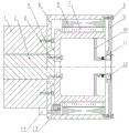
Fig. 1 is a schematic structural diagram of an integrated shell motor range extender with a rear auxiliary support according to the present invention.
FIG. 2 is a schematic view of a rotor assembly according to the present invention;
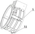
fig. 3 is a schematic structural diagram of the integrated housing according to the present invention.
In the figure: 1-engine, 2-crankshaft, 3-second bolt, 4-third bolt, 5-integrated shell, 51-first mounting hole, 6-stator component, 7-rotor component, 71-motor rotor, 72-rotor bracket, 8-first bolt, 9-cover plate, 10-auxiliary support shaft, 11-rotary transformer, 12-bearing, 13-starting gear ring and 14-starter.
Detailed Description
In order to make the objects, technical solutions and advantages of the present invention more apparent, the present invention is further described in detail by embodiments with reference to the accompanying drawings. It should be understood that the specific embodiments described herein are merely illustrative of the invention and are not intended to limit the invention.
An embodiment of the present invention provides an integrated casing motor range extender with a rear auxiliary support, as shown in fig. 1, including: the engine 1, the engine 1 is equipped with the crankshaft 2; the crankshaft 2 is rigidly and fixedly connected with the generator for transmitting power; the generator includes: the integrated shell 5, the stator assembly 6, the rotor assembly 7, the rotary transformer 11, the cover plate 9, the auxiliary support shaft 10 and the bearing 12; the integrated shell 5 is an integrated structure of a flywheel shell and a motor shell, the length of the motor can be shortened through integration, the overall structure is more compact, the integrated shell 5 is fixedly connected with a cover plate 9 through a first bolt 8, the stator assembly 6 is fixedly arranged in the integrated shell 5 and is fixedly connected with the cover plate 9, and the rotor assembly 7 is coaxially arranged in the stator assembly 6; as shown in fig. 2, the rotor assembly 7 includes a motor rotor 71 and a rotor bracket 72, and the rotor bracket 72 is an integrated structure of a flywheel and a bracket, so as to improve the reliability and transmission efficiency of the system; the large end of the auxiliary support shaft 10 is fixedly arranged on the inner wall of the rotor bracket 72, the small end of the auxiliary support shaft 10 is fixed with the outer ring of the bearing 12, and the outer ring of the bearing 12 rotates along with the rotor bracket 72 and the auxiliary support shaft 10; the inner ring of the bearing 12 is fixedly connected with a positioning shaft (not shown in the figure) on the cover plate 9, and the rotary transformer 11 is arranged on the auxiliary supporting shaft 10; the engine 1 is fixedly connected with the integrated shell 5 through a second bolt 3, and the crankshaft 2 is fixedly connected with the rotor bracket 72 through a third bolt 4; through the structural connection, kinetic energy is output by the crankshaft 2 of the engine 1 and is transmitted to the rotor support 72 rigidly connected with the crankshaft 2, and the rotor assembly 7 and the stator assembly 6 generate electricity under the electromagnetic action to output electric energy.
In one embodiment, continuing to refer to fig. 1, a starter ring gear 13 may also be provided, the starter ring gear 13 being drivingly connected to the rotor support 72; a starter 14 required for starting the starting gear ring 13 is configured, and the starter 14 is started to drive the starting gear ring 13 on the rotor assembly 7, so that the system is started; and the use condition can also be indicated whether to use the function of the starter and select whether the system is provided with the starter 14, so that the cost of the whole machine is optimal.
In some embodiments, as shown in fig. 3, the integrated housing 5 is provided with a first mounting hole 51 for mounting a support system.
Reference in the specification to "some embodiments," "one embodiment," or "an embodiment," etc., means that a particular feature, structure, or characteristic described in connection with the embodiment is included in at least one embodiment. Thus, the appearances of the phrases "in some embodiments," "in one embodiment," or "in an embodiment," or the like, in various places throughout this specification are not necessarily referring to the same embodiment. Furthermore, the particular features, structures, or characteristics may be combined in any suitable manner in one or more embodiments. Additionally, the various elements of the drawings of the present application are merely schematic illustrations and are not drawn to scale.
Having thus described several aspects of at least one embodiment of this invention, it is to be appreciated various alterations, modifications, and improvements will readily occur to those skilled in the art. Such alterations, modifications, and improvements are intended to be within the spirit and scope of the invention.
Claims (3)
1. An integrated housing motor range extender with rear auxiliary support, comprising: the engine is provided with a crankshaft; the crankshaft is rigidly and fixedly connected with the generator; the method is characterized in that:
the generator includes: the integrated motor comprises an integrated shell, a stator assembly, a rotor assembly, a rotary transformer, a cover plate, an auxiliary support shaft and a bearing; the integrated shell is fixedly connected with the cover plate through a first bolt, the stator assembly is fixedly arranged in the integrated shell and fixedly connected with the cover plate, and the rotor assembly is coaxially arranged in the stator assembly; the rotor assembly comprises a motor rotor and a rotor support, the large end of the auxiliary support shaft is fixedly arranged on the inner wall of the rotor support, the small end of the auxiliary support shaft is fixed with the outer ring of the bearing, the inner ring of the bearing is fixedly connected with the positioning shaft on the cover plate, and the rotary transformer is arranged on the auxiliary support shaft;
the engine is fixedly connected with the integrated shell through a second bolt, and the crankshaft is fixedly connected with the rotor support through a third bolt.
2. The integrated housing motor range extender with rear auxiliary support of claim 1 further comprising: and the starting gear ring is in transmission connection with the rotor support.
3. The integrated housing motor range extender with rear auxiliary support of claim 1 or 2, wherein: and a first mounting hole is formed in the integrated shell.
Priority Applications (1)
| Application Number | Priority Date | Filing Date | Title |
|---|---|---|---|
| CN202110900006.4A CN113726065A (en) | 2021-08-06 | 2021-08-06 | Integrated shell motor range extender with rear auxiliary support |
Applications Claiming Priority (1)
| Application Number | Priority Date | Filing Date | Title |
|---|---|---|---|
| CN202110900006.4A CN113726065A (en) | 2021-08-06 | 2021-08-06 | Integrated shell motor range extender with rear auxiliary support |
Publications (1)
| Publication Number | Publication Date |
|---|---|
| CN113726065A true CN113726065A (en) | 2021-11-30 |
Family
ID=78675010
Family Applications (1)
| Application Number | Title | Priority Date | Filing Date |
|---|---|---|---|
| CN202110900006.4A Pending CN113726065A (en) | 2021-08-06 | 2021-08-06 | Integrated shell motor range extender with rear auxiliary support |
Country Status (1)
| Country | Link |
|---|---|
| CN (1) | CN113726065A (en) |
Citations (6)
| Publication number | Priority date | Publication date | Assignee | Title |
|---|---|---|---|---|
| CN102223033A (en) * | 2011-05-27 | 2011-10-19 | 山东理工大学 | Generator for range extender of electric vehicle |
| CN105896855A (en) * | 2016-04-08 | 2016-08-24 | 东南大学 | Stator permanent magnet-type double-mechanical port motor for extended-range electric vehicle and power assembly |
| CN108995542A (en) * | 2018-09-06 | 2018-12-14 | 广西玉柴机器股份有限公司 | Motor integrated electric automobile distance increasing unit |
| CN109412328A (en) * | 2018-11-02 | 2019-03-01 | 宁波安信数控技术有限公司 | A kind of automobile travel increasing apparatus permanent magnet generator |
| CN208702594U (en) * | 2018-09-06 | 2019-04-05 | 广西玉柴机器股份有限公司 | The integrated motor structure of tape starting machine |
| CN210518010U (en) * | 2019-05-05 | 2020-05-12 | 浙江吉利控股集团有限公司 | Range extender generator and electric automobile |
-
2021
- 2021-08-06 CN CN202110900006.4A patent/CN113726065A/en active Pending
Patent Citations (6)
| Publication number | Priority date | Publication date | Assignee | Title |
|---|---|---|---|---|
| CN102223033A (en) * | 2011-05-27 | 2011-10-19 | 山东理工大学 | Generator for range extender of electric vehicle |
| CN105896855A (en) * | 2016-04-08 | 2016-08-24 | 东南大学 | Stator permanent magnet-type double-mechanical port motor for extended-range electric vehicle and power assembly |
| CN108995542A (en) * | 2018-09-06 | 2018-12-14 | 广西玉柴机器股份有限公司 | Motor integrated electric automobile distance increasing unit |
| CN208702594U (en) * | 2018-09-06 | 2019-04-05 | 广西玉柴机器股份有限公司 | The integrated motor structure of tape starting machine |
| CN109412328A (en) * | 2018-11-02 | 2019-03-01 | 宁波安信数控技术有限公司 | A kind of automobile travel increasing apparatus permanent magnet generator |
| CN210518010U (en) * | 2019-05-05 | 2020-05-12 | 浙江吉利控股集团有限公司 | Range extender generator and electric automobile |
Similar Documents
| Publication | Publication Date | Title |
|---|---|---|
| EP3778280B1 (en) | Engine and electric motor assembly, and vehicle driving device | |
| CN105927294A (en) | Waste gas turbine power generation device | |
| CN210518010U (en) | Range extender generator and electric automobile | |
| CN109026487B (en) | Integrated motor structure with starter | |
| CN113726065A (en) | Integrated shell motor range extender with rear auxiliary support | |
| CN216122073U (en) | Range extender structure with starting gear ring and flywheel shell connecting plate | |
| CN216122001U (en) | Integrated shell and rear-end output range extender structure | |
| CN114744826A (en) | External rotor generator for range extender | |
| CN2783608Y (en) | Flywheel motor | |
| CN109412337B (en) | System structure of range extender | |
| CN208272781U (en) | A kind of composite structure of crankshaft-flywheel and generator | |
| CN216121972U (en) | Range extender structure with balance block and isolated motor cavity | |
| CN201581985U (en) | Transitional connection structure of engine flywheel housing and generator of hybrid electric vehicle | |
| CN216122119U (en) | Range extender structure with rear support and stator temperature measurement | |
| CN216121973U (en) | Range extender structure with integrated support and high-precision rotor | |
| CN216122003U (en) | Range extender structure with rear-end output and independent motor cavity | |
| CN216077320U (en) | Range extender structure with rear-end output and balancing weight | |
| CN216122066U (en) | Range extender motor structure | |
| CN216086345U (en) | Range extender motor structure with shell supported | |
| CN217643045U (en) | External rotor generator for range extender | |
| CN217643044U (en) | External rotor generator for range extender | |
| CN113756943A (en) | Integrated shell range extender structure with stator temperature measurement function | |
| CN216121977U (en) | Structure for range extender | |
| CN216122051U (en) | Junction box integrated motor with rear support | |
| CN216121987U (en) | Range extender structure with three-phase line fixing support |
Legal Events
| Date | Code | Title | Description |
|---|---|---|---|
| PB01 | Publication | ||
| PB01 | Publication | ||
| SE01 | Entry into force of request for substantive examination | ||
| SE01 | Entry into force of request for substantive examination | ||
| RJ01 | Rejection of invention patent application after publication |
Application publication date: 20211130 |
|
| RJ01 | Rejection of invention patent application after publication |