CN113711281A - Monitoring system, monitoring method, and program - Google Patents
Monitoring system, monitoring method, and program Download PDFInfo
- Publication number
- CN113711281A CN113711281A CN201980095133.2A CN201980095133A CN113711281A CN 113711281 A CN113711281 A CN 113711281A CN 201980095133 A CN201980095133 A CN 201980095133A CN 113711281 A CN113711281 A CN 113711281A
- Authority
- CN
- China
- Prior art keywords
- information
- terminal
- position information
- life circle
- circle
- Prior art date
- Legal status (The legal status is an assumption and is not a legal conclusion. Google has not performed a legal analysis and makes no representation as to the accuracy of the status listed.)
- Pending
Links
- 238000012544 monitoring process Methods 0.000 title claims abstract description 109
- 238000000034 method Methods 0.000 title claims description 69
- 230000006870 function Effects 0.000 claims description 26
- 238000009825 accumulation Methods 0.000 claims description 4
- 238000012937 correction Methods 0.000 claims description 2
- 230000001012 protector Effects 0.000 abstract description 68
- 238000004891 communication Methods 0.000 description 44
- 238000010586 diagram Methods 0.000 description 33
- 230000005540 biological transmission Effects 0.000 description 12
- 230000007958 sleep Effects 0.000 description 9
- 238000012545 processing Methods 0.000 description 8
- 230000009471 action Effects 0.000 description 7
- 238000005192 partition Methods 0.000 description 7
- 230000001133 acceleration Effects 0.000 description 6
- 230000008569 process Effects 0.000 description 6
- 230000008859 change Effects 0.000 description 5
- 230000001413 cellular effect Effects 0.000 description 3
- 230000003247 decreasing effect Effects 0.000 description 3
- 230000007423 decrease Effects 0.000 description 2
- 238000012905 input function Methods 0.000 description 2
- 230000004048 modification Effects 0.000 description 2
- 230000000474 nursing effect Effects 0.000 description 2
- XLYOFNOQVPJJNP-UHFFFAOYSA-N water Substances O XLYOFNOQVPJJNP-UHFFFAOYSA-N 0.000 description 2
- HBBGRARXTFLTSG-UHFFFAOYSA-N Lithium ion Chemical compound [Li+] HBBGRARXTFLTSG-UHFFFAOYSA-N 0.000 description 1
- 230000002301 combined effect Effects 0.000 description 1
- 239000000470 constituent Substances 0.000 description 1
- 229910001416 lithium ion Inorganic materials 0.000 description 1
- 238000012986 modification Methods 0.000 description 1
- 210000001747 pupil Anatomy 0.000 description 1
- 230000009467 reduction Effects 0.000 description 1
- 239000007787 solid Substances 0.000 description 1
- 230000008685 targeting Effects 0.000 description 1
- 230000002618 waking effect Effects 0.000 description 1
Images


Classifications
-
- G—PHYSICS
- G08—SIGNALLING
- G08B—SIGNALLING OR CALLING SYSTEMS; ORDER TELEGRAPHS; ALARM SYSTEMS
- G08B21/00—Alarms responsive to a single specified undesired or abnormal condition and not otherwise provided for
- G08B21/02—Alarms for ensuring the safety of persons
- G08B21/0202—Child monitoring systems using a transmitter-receiver system carried by the parent and the child
- G08B21/0294—Display details on parent unit
-
- H—ELECTRICITY
- H04—ELECTRIC COMMUNICATION TECHNIQUE
- H04W—WIRELESS COMMUNICATION NETWORKS
- H04W4/00—Services specially adapted for wireless communication networks; Facilities therefor
- H04W4/02—Services making use of location information
- H04W4/029—Location-based management or tracking services
-
- G—PHYSICS
- G06—COMPUTING; CALCULATING OR COUNTING
- G06Q—INFORMATION AND COMMUNICATION TECHNOLOGY [ICT] SPECIALLY ADAPTED FOR ADMINISTRATIVE, COMMERCIAL, FINANCIAL, MANAGERIAL OR SUPERVISORY PURPOSES; SYSTEMS OR METHODS SPECIALLY ADAPTED FOR ADMINISTRATIVE, COMMERCIAL, FINANCIAL, MANAGERIAL OR SUPERVISORY PURPOSES, NOT OTHERWISE PROVIDED FOR
- G06Q50/00—Information and communication technology [ICT] specially adapted for implementation of business processes of specific business sectors, e.g. utilities or tourism
- G06Q50/10—Services
-
- G—PHYSICS
- G08—SIGNALLING
- G08B—SIGNALLING OR CALLING SYSTEMS; ORDER TELEGRAPHS; ALARM SYSTEMS
- G08B21/00—Alarms responsive to a single specified undesired or abnormal condition and not otherwise provided for
- G08B21/02—Alarms for ensuring the safety of persons
- G08B21/0202—Child monitoring systems using a transmitter-receiver system carried by the parent and the child
- G08B21/0233—System arrangements with pre-alarms, e.g. when a first distance is exceeded
-
- G—PHYSICS
- G08—SIGNALLING
- G08B—SIGNALLING OR CALLING SYSTEMS; ORDER TELEGRAPHS; ALARM SYSTEMS
- G08B21/00—Alarms responsive to a single specified undesired or abnormal condition and not otherwise provided for
- G08B21/02—Alarms for ensuring the safety of persons
- G08B21/0202—Child monitoring systems using a transmitter-receiver system carried by the parent and the child
- G08B21/0272—System arrangements wherein the object is to detect exact location of child or item using triangulation other than GPS
-
- H—ELECTRICITY
- H04—ELECTRIC COMMUNICATION TECHNIQUE
- H04W—WIRELESS COMMUNICATION NETWORKS
- H04W4/00—Services specially adapted for wireless communication networks; Facilities therefor
- H04W4/02—Services making use of location information
- H04W4/021—Services related to particular areas, e.g. point of interest [POI] services, venue services or geofences
-
- H—ELECTRICITY
- H04—ELECTRIC COMMUNICATION TECHNIQUE
- H04W—WIRELESS COMMUNICATION NETWORKS
- H04W4/00—Services specially adapted for wireless communication networks; Facilities therefor
- H04W4/02—Services making use of location information
- H04W4/025—Services making use of location information using location based information parameters
- H04W4/027—Services making use of location information using location based information parameters using movement velocity, acceleration information
Landscapes
- Engineering & Computer Science (AREA)
- Business, Economics & Management (AREA)
- Health & Medical Sciences (AREA)
- General Health & Medical Sciences (AREA)
- Computer Networks & Wireless Communication (AREA)
- Signal Processing (AREA)
- Child & Adolescent Psychology (AREA)
- Physics & Mathematics (AREA)
- General Physics & Mathematics (AREA)
- Emergency Management (AREA)
- Tourism & Hospitality (AREA)
- Human Resources & Organizations (AREA)
- Economics (AREA)
- Marketing (AREA)
- Primary Health Care (AREA)
- Strategic Management (AREA)
- General Business, Economics & Management (AREA)
- Theoretical Computer Science (AREA)
- Radar, Positioning & Navigation (AREA)
- Alarm Systems (AREA)
- Telephonic Communication Services (AREA)
- Management, Administration, Business Operations System, And Electronic Commerce (AREA)
- Emergency Alarm Devices (AREA)
- Telephone Function (AREA)
Abstract
A monitoring system (10) includes: an information accumulation program (32) that accumulates positional information of a user terminal determined based on information uploaded from a user terminal (100) carried by a person under guardianship; a life circle determination program (33) for determining a life circle of the person under guardianship based on the position information accumulated in the predetermined period of time in the accumulated position information; a determination program (37) for determining the positional relationship between the position of the user terminal determined based on the positional information of the user terminal and the life circle; and an alarm notification program (28) for notifying the judgment result to the protector terminal (209).
Description
Technical Field
The present invention relates to a monitoring system, a monitoring method, and a program having a monitoring function suitable for monitoring children or elderly people who wander, for example.
Background
In the case where a child becomes a pupil and often a person moves more, the protector is most concerned about ensuring the safety of the child. In addition, the most concern is still to ensure the safety of the elderly people who have a wandering habit, such as families or nursing facilities.
Therefore, a monitoring system is put to practical use, in which a guardian such as a guardian, a family, or a staff in a nursing facility grasps a location of a subject (hereinafter also referred to as a "guardian") to be monitored such as a child or a wandering elderly in real time (see, for example, https:// dekiru. net/alarm/15964 (24/10/2017)).
Disclosure of Invention
By using such a monitoring system, the guardian can grasp not only the location of the monitored person in real time but also the movement locus by tracking the location in time series.
Thus, for example, the protector can grasp whether the child moves along a correct route for learning, whether the child is within a normal action range, that is, within a life circle, when playing in a usual park, and can grasp that the child is out of the normal action range, that is, out of the life circle.
However, the guardian is not necessarily always able to observe the location of the monitored person. Therefore, even if the person under guardianship gets out of the life circle, the person under guardianship cannot be immediately grasped, and may be noticed after a considerable time has elapsed. Alternatively, even in a case where the guardian is constantly observing the location of the monitored person, if the guardian does not grasp the life circle of the monitored person, there is a possibility that the monitored person is not noticed to be out of the life circle.
The present invention has been made in view of the above circumstances, and an object thereof is to provide a monitoring system, a monitoring method, and a program that can determine a life circle to be used for a monitored person and notify a guardian of a positional relationship between the monitored person and the life circle.
In order to achieve the above object, the present invention employs the following means.
That is, a monitoring system according to a first aspect of the present invention includes: an information accumulation unit that accumulates position information of a first terminal determined based on information uploaded from the first terminal carried by a person under guardianship; a life circle determination unit that determines a life circle of the person under guardianship based on the positional information accumulated for a predetermined period of time among the accumulated positional information; a determination unit that determines a positional relationship between the position of the first terminal and the life circle, the positional relationship being determined based on the positional information of the first terminal; and a notification unit configured to notify a second terminal designated in advance of a determination result of the determination unit.
Further, according to the monitoring system of the first aspect, in the monitoring system of the second aspect of the present invention, the life circle determination unit determines the life circle based on a section belonging to the predetermined number of times or more of the positional information accumulated in the predetermined period in each section in the map divided into the plurality of sections in advance.
Further, according to the monitoring system of the first aspect, in the monitoring system of the third aspect of the present invention, the living coil determining unit determines an area including each position corresponding to the position information accumulated for a predetermined period as the living coil.
Further, in addition to the monitoring system according to the third aspect, in the monitoring system according to the fourth aspect of the present invention, the shape of the region is a convex shape, a circular shape, or a rectangular shape.
In the monitoring system according to the fifth aspect of the present invention, the life circle determining unit enlarges or reduces the determined life circle based on a predetermined criterion.
According to the monitoring system of the second aspect, in the monitoring system of the sixth aspect of the present invention, the predetermined period is the past 30 days, and the predetermined number of times is two.
According to the monitoring system of any one of the first to sixth aspects, in the monitoring system of the seventh aspect of the present invention, the life circle determination unit is configured to determine the life circle based on the position information accumulated under the predetermined condition, among the position information accumulated over the predetermined period.
According to the monitoring system of the seventh aspect of the present invention, in the monitoring system of the eighth aspect of the present invention, the position information accumulated under the predetermined condition is any one of position information accumulated on weekdays, position information accumulated on weekends and holidays, and position information accumulated on a specific day of the week.
According to the monitoring system of the seventh or eighth aspect, in the monitoring system of the ninth aspect of the present invention, the position information accumulated in accordance with the predetermined condition is position information accumulated in a specific time period.
A monitoring system according to a tenth aspect of the present invention is the monitoring system according to any one of the first through ninth aspects, further including: a map information creation unit that creates map information in which a life circle has been specified on a map; and a transmission unit that transmits the created map information to the second terminal.
The monitoring system according to any one of the first to tenth aspects of the present invention is the monitoring system according to an eleventh aspect of the present invention, further comprising a life circle correction unit configured to correct the determined life circle in accordance with an instruction from the second terminal.
According to the monitoring system of any one of the first to tenth aspects, in the monitoring system of the twelfth aspect of the present invention, the notification unit notifies the determination result when the determination unit determines that the position of the first terminal is outside the living circle.
A monitoring system according to a thirteenth aspect of the present invention includes: a receiving unit that receives information specifying a life circle of a person under guardianship; an information accumulation unit that accumulates position information of a first terminal determined based on information uploaded from the first terminal carried by a person under guardianship; a determination unit that determines a positional relationship between the position of the first terminal and the life circle, the positional relationship being determined based on the positional information of the first terminal; and a notification unit configured to notify a second terminal designated in advance of a determination result of the determination unit.
A monitoring method according to a fourteenth aspect of the present invention is a monitoring method implemented by a processor, including: a step in which a processor stores, in a storage device, position information of a first terminal determined based on information uploaded from the first terminal carried by a person under guardianship; a step in which the processor determines a life circle of the person under guardianship based on the positional information stored in the storage device for a predetermined period of time; a step in which the processor determines the positional relationship between the position of the first terminal and the life circle, which is determined based on the position information of the first terminal; and a step in which the processor notifies a pre-designated second terminal of the result of the determination.
A program according to a fifteenth aspect of the present invention is for causing a processor to realize the following functions: a function of accumulating, in a storage device, position information of a first terminal determined based on information uploaded from the first terminal carried by a person under guardianship; a function of determining a life circle of the person under guardianship based on the position information stored in the storage device within a predetermined period; a function of determining a positional relationship between the position of the first terminal determined based on the position information of the first terminal and the life circle; and a step function of notifying the result of the determination to a second terminal designated in advance.
According to the monitoring system, the monitoring method, and the program of the present invention, by adopting the above-described means, it is possible to determine a life circle for a person under guardianship. In addition, even when the person under guardianship gets out of the life circle, the person under guardianship can detect the situation and notify the person under guardianship.
Drawings
Fig. 1 is a conceptual diagram for explaining a concept of a monitoring system to which a monitoring method according to an embodiment of the present invention is applied.
Fig. 2 is a schematic diagram showing an example of a functional configuration of the user terminal.
Fig. 3 is a block diagram showing an example of a configuration of a monitoring system to which the monitoring method according to the embodiment of the present invention is applied.
Fig. 4 is a data configuration diagram showing an example of the user registration DB.
Fig. 5 is a data configuration diagram showing an example of the upload information DB.
Fig. 6 is a diagram for explaining an example of a first determination method of a life circle.
Fig. 7 is a diagram for explaining another example of the first determination method of the life circle.
Fig. 8 is a diagram for explaining an example of a second determination method of a life circle.
Fig. 9 is a diagram for explaining an example of the third determination method of the life circle.
Fig. 10 is a diagram for explaining an example of a fourth determination method of a life circle.
Fig. 11 is a diagram for explaining an example of a fifth determination method of a life circle.
Fig. 12 is a diagram for explaining an example of a sixth determination method for a life circle.
Fig. 13 is a schematic diagram showing an example of the setting screen.
Fig. 14 is a schematic view illustrating a part of a straight line defining the outer periphery of a living circle.
Fig. 15 is a schematic diagram showing an example of display on the display screen of the patron terminal for setting a predetermined reference.
Fig. 16 is map information for explaining a method of setting a life circle by the life circle correction program.
Fig. 17 is a conceptual diagram showing an example of map information showing a positional relationship between a life circle and a current position of a user terminal.
Fig. 18 is a schematic diagram showing an example of map information showing a movement trajectory of the user terminal.
Fig. 19 is a flowchart showing a flow of processing related to determination of a life circle and determination of a positional relationship between a user terminal and the life circle.
Detailed Description
Fig. 1 is a conceptual diagram for explaining a concept of a monitoring system to which a monitoring method according to an embodiment of the present invention is applied.
The monitoring system 10 grasps the location of the user terminal 100 based on information uploaded from the terminal 100 (hereinafter, referred to as "user terminal 100") carried by a person under guardianship (e.g., a person under guardianship such as a child or an elderly person), determines the life circle of the person under guardianship based on the history of the location of the user terminal 100, and notifies the terminal 200 (hereinafter, referred to as "protector terminal 200") of the guardian (e.g., a protector or supervisor of the person under guardianship).
Fig. 2 is a schematic diagram showing an example of a functional configuration of the user terminal.
The user terminal 100 includes: a SIM card 110; a transmitting/receiving function 120 capable of communicating with the monitoring system 10 via the base station 60 by a cellular system such as 3G, LTE (registered trademark), 4G, or 5G; a GPS function 130 to acquire GPS information; a WiFi function 140 that acquires MAC addresses of neighboring WiFi routers together with information indicating the reception intensity (RSSI) of radio waves received from the WiFi routers; an acceleration sensor 150 that measures the acceleration of the user terminal 100; and a rechargeable battery 160 such as a lithium ion battery that supplies electric power to the user terminal 100. Since all of these apply well-known techniques, a more detailed description is avoided here.
The user terminal 100 is not limited to directly communicating with the base station 60 by the transmission/reception function 120, and may indirectly communicate with the base station 60 via the WiFi router 61, as shown by the dotted line in fig. 1. In this case, the WiFi router 61 can be realized by a smartphone, for example.
The user terminal 100 may communicate with the monitoring system 10 by using a communication method other than the cellular method, such as LPWA (Low Power Wide Area). In this case, the SIM card 110 is not required in the user terminal 100. In addition, the base station 60 is replaced with a gateway. In this way, the user terminal 60 serves as a base station or a gateway according to the communication method, but hereinafter, as an example, a method in which the user terminal 100 communicates with the monitoring system 10 by a cellular method, that is, via the base station 60 will be described.
The user terminal 100 is lightweight and has a small size so that there is no burden even if a child or an old person carries it, and a unique identification number is preset for each user terminal 100.
To start using the monitoring system 10, first, the monitoring system 10 needs to register the user terminal 100 with the user. The user registration is performed by transmitting the identification number a of the user terminal 100 from the smart phone or PC, i.e., the protector terminal 200, to the monitoring system 10 via the communication network 70 such as the internet. The patron terminal 200.
Accordingly, the monitoring system 10 recognizes the user terminal 100 having the identification number a as the user terminal 100 of the monitoring target (the monitored target), and recognizes the mail address of the protector terminal 200 for transmitting the identification number a as the address b of the protector terminal 200 (hereinafter, also referred to as "protector address b"). In this way, when the user terminal 100 and the guardian terminal 200 are recognized by the monitoring system 10, the user registration is completed.
After the user registration, if the acceleration sensor 150 detects an acceleration equal to or greater than a predetermined value, in other words, if the user terminal 100 is moving, the user terminal 100 wakes up and acquires GPS information at intervals of, for example, every 1.5 minutes set by default by the GPS function 130. The GPS information includes not only the position information but also a time stamp indicating the time of positioning.
The user terminal 100 also uploads the acquired GPS information to the monitoring system 10 together with the identification number a of the user terminal 100 using the transmitting and receiving function 120. At this time, the transmission/reception function 120 may acquire the remaining battery level information from the battery 160, add the remaining battery level information, and upload the remaining battery level information to the monitoring system 10.
However, there are also cases where the user terminal 100 is located in a place where the GPS function 130 cannot acquire GPS information. In such a case, the user terminal 100 acquires MAC addresses of a plurality of WiFi routers in the periphery together with the reception intensity information of the radio wave from each WiFi router by the WiFi function 140. The reception intensity information also includes a time stamp indicating the time when the radio wave is transmitted from the WiFi router.
Instead of the GPS information, the user terminal 100 uploads the acquired MAC addresses of the WiFi routers and the reception intensity information of the radio waves from the WiFi routers together with the identification number a of the user terminal 100 from the transmission/reception function 120 to the monitoring system 10. The MAC address of the WiFi router and the reception intensity information of the radio wave from the WiFi router are used for positioning by the positioning server 40 as described later.
In addition, when the user terminal 100 is located in a location where the GPS function 130 cannot acquire GPS information, the user terminal 100 may receive the radio wave from the base station 60 by the transmission/reception function 120, and may upload the reception intensity information of the radio wave from the base station 60, together with the identification number a of the user terminal 100 and a time stamp indicating the time when the radio wave is received from the base station 60, from the transmission/reception function 120 to the monitoring system 10 via the base station 60 instead of the GPS information. The reception intensity information of the radio wave from the base station 60 is also used for positioning by the positioning server 40 as described later.
In addition, the user terminal 100 may selectively upload not only the MAC address of the WiFi router and the reception intensity information of the radio wave from the WiFi router, but also both the reception intensity information of the radio wave from the base station 60 and the time stamp to the monitoring system 10 instead of the GPS information.
Further, even in the case where GPS information can be acquired, the user terminal 100 may upload, in addition to the GPS information, the MAC address of the WiFi router and the reception intensity information of the electric wave from the WiFi router, and the reception intensity information of the electric wave from the base station 60 and the time stamp to the monitoring system 10.
Thus, the monitoring system 10 can use, in the positioning of the user terminal 100, not only the position information determined based on the GPS information, but also either the position information determined by the positioning server 40 based on the MAC address of the WiFi router and the reception intensity information of the radio wave from the WiFi router, or the position information determined by the positioning server 40 based on the radio wave intensity of the radio wave from the base station 60.
On the other hand, as long as the acceleration sensor 150 does not detect the acceleration of the predetermined value or more, in other words, as long as the user terminal 100 is not moving, the user terminal 100 does not perform acquisition of the GPS information, reception of the radio wave from the WiFi router, and reception of the radio wave from the base station 60, and does not upload the information to the monitoring system 10. In this way, when the user terminal 100 does not move, the user terminal 100 sleeps. This saves the electric power of battery 160.
Further, no operation button exists in the user terminal 100. All setting operations (for example, setting and changing of an interval for uploading) on the user terminal 100 are performed remotely via the monitoring system 10 by an instruction from the guardian terminal 200. Therefore, even if the user terminal 100 is not operated by the person under guardianship, the user terminal 100 automatically wakes up/sleeps, and at the time of waking up, information is uploaded to the monitoring system 10 at set intervals.
Fig. 3 is a block diagram showing an example of a configuration of a monitoring system to which the monitoring method according to the embodiment of the present invention is applied.
The monitoring system 10 includes: a CPU 14, a communication unit 16, a storage device 20, and a memory 30, which are connected to each other via a bus 12.
The CPU 14 is a computer that controls the internal operation of the monitoring system 10 in accordance with various programs 31 to 39 stored in the memory 30.
The communication unit 16 can receive information uploaded from the user terminal 100 via the base station 60. The positioning server 40 and the protector terminal 200 can communicate with each other via a communication network 70 such as the internet.
The storage device 20 stores a user registration database 22 (hereinafter, referred to as "user registration DB" 22) that manages user registration information (identification number a and guardian address b) transmitted from the guardian terminal 200, and an upload information database 24 (hereinafter, referred to as "upload information DB" 24) that accumulates information uploaded from the user terminal 100 and position information determined by the positioning server 40, using, for example, an SSD (Solid State Drive) or an HDD (Hard Disk Drive).
The registration management program 31 performs the aforementioned processing for user registration. The user registration is performed by transmitting the identification number a of the user terminal 100 from the guardian terminal 200, for example, a smartphone or PC, to the monitoring system 10 via the communication network 70 such as the internet. Thereby, the transmitted identification number a is received by the communication unit 16, and the mail address used for the protector terminal 200 to transmit the identification number a is recognized by the communication unit 16.
Fig. 4 is a data configuration diagram showing an example of the user registration DB.
The user registration DB22 contains an identification number a, a guardian address b, and life circle position information h as data items. As will be described later, the life circle position information h is determined by the life circle determination program 33 and written. Although not shown in fig. 4, other information such as the address of the protection owner, the year, month, and day of the use start of the user terminal 100, and the like may be added as the data item.
The registration management program 31 writes the identification number a received by the communication unit 16 in the user registration DB 22. In addition, the mail address of the identified protector terminal 200 is written as the protector address b to the user registration DB 22. Thereby, the user registration processing is completed.
When the user registration process is completed, the monitoring system 10 can receive information uploaded from the user terminal 100 having the identification number a. The information that can be uploaded can include: the identification number a, GPS information, the MAC address of the WiFi router, reception intensity information of the radio wave received by the user terminal 100 from the WiFi router, a time stamp indicating the reception time, reception intensity information of the radio wave received by the user terminal 100 from the base station 60, remaining battery amount information, and the like.
Further, the user terminal 100 may not be able to receive any of GPS information, radio waves from the WiFi router, and radio waves from the base station 60. Therefore, for example, in the case where the user terminal 100 is not capable of receiving GPS information, the uploaded information does not include GPS information. On the other hand, in the case where the user terminal 100 cannot receive the electric wave from the WiFi router, the uploaded information does not include the MAC address of the WiFi router and the reception intensity information of the electric wave from the WiFi router. In addition, when the user terminal 100 cannot receive the radio wave from the base station 60, the uploaded information does not include the reception intensity information of the radio wave from the base station 60 and the time stamp indicating the reception time.
The information uploaded from the user terminal 100 at the set interval is received by the communication unit 16. As will be described later, the interval can be arbitrarily set and changed by the setting program 36 in accordance with an instruction from the protector terminal 200.
The information accumulation program 32 writes the corresponding information to each data item specified by the upload information DB24 based on the uploaded information.
Fig. 5 is a data configuration diagram showing an example of the upload information DB.
The upload information DB24 includes, as data items, a time stamp c, an identification number a, GPS position information d, WiFi position information e, base station position information f, battery remaining amount information g, and the like. While not shown in fig. 5, the MAC address of the WiFi router, the reception intensity of the radio wave from the base station 60, and the like may be added as data items as appropriate.
When the uploaded information includes the identification information a and the GPS information, the information accumulation program 32 accumulates the identification number a and the GPS information as the identification number a and the GPS position information d in the upload information DB 24. In addition, the time stamp included in the GPS information is stored as the time stamp c in the transmission information DB 24.
On the other hand, when the uploaded information includes the MAC address of the WiFi router and the reception intensity information of the radio wave from the WiFi router, the information accumulation program 32 writes the time stamp included in the reception intensity information as the time stamp c into the upload information DB24, and outputs the MAC address and the reception intensity information from the communication unit 16 to the positioning server 40 via the communication network 70.
When the uploaded information includes the reception intensity information of the radio wave from the base station 60 and the time stamp, the information accumulation program 32 writes the time stamp as the time stamp c in the upload information DB24, and outputs the reception intensity information of the radio wave from the base station 60 to the positioning server 40 via the communication network 70.
When the MAC address and the reception strength information are transmitted from the communication unit 16, the positioning server 40 determines the position of the user terminal 100 based on these pieces of information, and returns the corresponding position information (for example, latitude and longitude information) to the communication unit 16 as WiFi position information e via the communication network 70.
When the communication unit 16 transmits the reception intensity information of the radio wave from the base station 60, the positioning server 40 determines the position of the user terminal 100 based on the information, and returns the corresponding position information (for example, latitude and longitude information) to the communication unit 16 as the base station position information f via the communication network 70.
The monitoring system 10 can determine the position of the user terminal 100 even in a place where the GPS signal cannot be acquired, such as a platform of a subway, by using the positioning server 40. Such a positioning server 40 can be implemented using a known technique such as geoLocation provided by Google corporation, and therefore a more detailed description is avoided.
When the WiFi position information e and/or the base station position information f are returned from the positioning server 40 to the communication unit 16, the information accumulation program 32 accumulates the WiFi position information e and/or the base station position information f in the transmission information DB24 in association with the corresponding time stamps.
In this way, each time information is uploaded from the user terminal 100, at least one of the location information d, e, and f of the user terminal 100 is stored in the upload information DB24 in association with the time stamp c.
In this way, since the monitoring system 10 collectively stores the location information of each user terminal 100 in the upload information DB24, each user terminal 100 only needs to have a minimum necessary memory capacity, and the cost of the user terminal 100 can be reduced.
The life circle determination program 33 determines a life circle, which is a normal action range of the person under guardianship, based on the time stamp c, with respect to the position information d, e, and f stored for a predetermined period among the position information d, e, and f stored in the upload information DB 24. The predetermined period is set to a default value such as the past 30 days, for example, but as will be described later, the predetermined period can be set and changed to an arbitrary period by performing necessary input from the protector terminal 200 using the setting program 36.
The life circle determination program 33 can also determine a life circle more precisely by using the position information d, e, f accumulated under the predetermined condition among the position information d, e, f accumulated during the predetermined period.
By setting the predetermined condition to the weekday, the life circle of the weekday can be determined based on the time stamp c with only the position information d, e, and f accumulated on the weekday as objects. Further, by setting the predetermined conditions to weekends and holidays, it is possible to determine the life circle of the weekend and holiday based on the time stamp c by targeting only the position information d, e, f accumulated on the weekend and holiday. Then, the following is the case: by setting the predetermined condition to a specific day of the week (for example, friday), it is possible to determine the life circle for the specific day of the week with only the position information d, e, f accumulated on the specific day of the week as the target based on the time stamp c.
Further, as the predetermined condition, a specific time zone may be set. Thus, based on the time stamp c, in addition to the setting of the day of the week described above, it is possible to more finely determine the life circle as a life circle in the morning of weekdays (for example, from 6 pm to 10 pm), a life circle in the daytime of weekdays (for example, from 10 pm to 5 pm), or a life circle in the evening of weekdays (for example, from 5 pm to 11 pm). As the predetermined condition, only the time zone may be set without setting the day of the week.
The normal action range is not generally determined all the time, and the weekday, the weekend, the holiday, the morning, the noon, the evening, and the like are greatly different, and the life circle determination program 33 can determine various life circles based on a predetermined period, a predetermined condition, and further a predetermined criterion described later.
The predetermined period, the predetermined condition, and the predetermined reference can also be set and changed by inputting necessary data from the protector terminal 200 using the setting program 36, as will be described later.
A specific example of the process for determining a life circle performed by the life circle determining program 33 will be described with reference to the drawings. In the following example, a case will be described in which a life circle is determined based on positional information d, e, and f accumulated over the past 30 days as a predetermined period. However, as described above, when predetermined conditions are set as well as the day of the week or the time zone, the same processing is performed for the life circle determination, with only the positional information to be considered being different.
The life circle determining program 33 targets only the positional information d, e, and f stored in a predetermined period (for example, the past 30 days) among the positional information d, e, and f of the specific user terminal 100 stored in the upload information DB 24.
The life circle determining program 33 can determine a life circle by various methods as described below using any one of the position information d, e, and f stored in the predetermined period.
When 2 or more of the GPS position information d, the WiFi position information e, and the base station position information f are stored for the same or regarded as the same time stamp c, the life circle determination program 33 uses either one piece of position information or one piece of position information determined by an appropriate weighting from a plurality of pieces of position information.
Fig. 6 is a diagram for explaining an example of a first determination method of a life circle.
In the first determination method, a life circle is determined using a map divided into a plurality of sections in advance.
The map illustrated in fig. 6 is a well-known UTM mesh map, and is divided into a plurality of square partitions having a size corresponding to 100 meters in length and width, for example.
The life circle determination program 33 determines a section to which the position information accumulated in each section of the map within a predetermined period belongs, a predetermined number of times (for example, twice) or more, as a life circle.
For example, in the map illustrated in fig. 6, the plot points P21 to P30 correspond to the position information accumulated in the predetermined period, respectively, the segment L3T3 includes the plot points P21, P22, and P24, the segment L3T2 includes the plot points P28, P29, and P30, and the segment L4T2 includes the plot points P25, P26, and P27.
That is, since the positional information accumulated in the predetermined period belongs to the partition L3T3, the partition L3T2, and the partition L4T2 twice or more, the life circle determination program 33 determines the region in which the partition L3T3, the partition L3T2, and the partition L4T2 are combined as the life circle K.
On the other hand, the segment L3T4 includes only the plot point P23, and the position information accumulated in the predetermined period belongs to the segment L3T4 only once, for example, and therefore is not regarded as the life circle K.
When the life circle determination program 33 determines a life circle by the first determination method, the map to be used is not necessarily limited to a map divided into squares as in the UTM grid map, but may be a map divided into arbitrary shapes, for example, a life circle may be determined using a map divided for each dwelling as in the dwelling division map. This will be described with reference to fig. 7.
Fig. 7 is a diagram for explaining another example of the first determination method of the life circle.
It should be understood that in the residence section diagram shown in fig. 7, only 1-5 buns are briefly displayed in sections for the sake of illustration.
In the map illustrated in fig. 7, the plot points P21 to P30 correspond to the position information accumulated in the predetermined period, respectively, and the 3-point illustrated in fig. 7 includes plot points P21 to P24, and the 5-point includes plot points P25 to P30.
That is, since the positional information belongs to 3-terns and 5-terns, for example, twice or more, the life circle determining program 33 determines the region in which the 3-terns and 5-terns are combined as the life circle K.
The life circle determination program 33 can also determine the life circle K by the following second determination method.
Fig. 8 is a diagram for explaining an example of the second determination method of the life circle.
In the second determination method, as shown in fig. 6 and 7, the circle of life K can be determined using a map divided into sections, but as shown in fig. 8, the circle of life K can be determined using a map not divided into sections.
For example, in the map illustrated in fig. 8, the plot points P21 to P30 correspond to the position information accumulated in a predetermined period.
In the second determination method, as illustrated in fig. 8, the life circle determination program 33 can determine a minimum convex region including all the plot points P21 to P30 displayed on the map as the life circle K.
The life circle determination program 33 may determine the life circle K by a third determination method described below.
Fig. 9 is a diagram for explaining an example of the third determination method of the life circle.
Even in the third determination method, as shown in fig. 6 and 7, the circle of life K can be determined using a map divided into sections, but as shown in fig. 9, the circle of life K can be determined using a map not divided into sections.
For example, in the map illustrated in fig. 9, the plot points P21 to P30 correspond to the position information accumulated in a predetermined period.
In the third determination method, as illustrated in fig. 9, the life circle determination program 33 can determine the minimum circular area including all the plot points P21 to P30 displayed on the map as the life circle K.
Further, the life circle determining program 33 may determine the life circle K by a fourth determining method described below.
Fig. 10 is a diagram for explaining an example of a fourth determination method of a life circle.
Even with the fourth determination method, the circle of life K can be determined using the map divided into the sections as shown in fig. 6 and 7, but the circle of life K can also be determined using the map not divided into the sections as shown in fig. 10.
For example, in the map illustrated in fig. 10, the plot points P21 to P30 correspond to the position information accumulated in a predetermined period.
In the fourth determination method, as illustrated in fig. 10, the life circle determination program 33 can determine an area indicated by a minimum rectangle including all the plot points P21 to P30 displayed on the map as the life circle K.
The life circle determination program 33 may determine the life circle K by a fifth determination method described below.
Fig. 11 is a diagram for explaining an example of a fifth determination method of a life circle.
Even with the fifth determination method, the circle of life K can be determined using the map divided into the sections as shown in fig. 6 and 7, but the circle of life K can be determined using the map not divided into the sections as shown in fig. 11.
For example, in the map illustrated in fig. 11, the plotted points indicated by the water droplet marks correspond to the position information accumulated in the predetermined period.
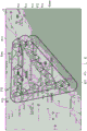
In the fifth determination method, as illustrated in fig. 11, the life circle determination program 33 determines the minimum area including all the plot points displayed on the map as the life circle K. Therefore, several plot points P11 to P15 located at the outermost portion of the living circle K are selected from the displayed plot points, and an area formed by connecting adjacent plot points by a straight line L is determined as the living circle K, with only the selected plot points being targeted.
The life circle determination program 33 may determine the life circle K by a sixth determination method described below.
Fig. 12 is a diagram for explaining an example of a sixth determination method for a life circle.
In the sixth determination method, the life circle determination program 33 determines the life circle K using the route of the road or the railway. Therefore, it is necessary to use a map including information on a road or a railway route. If the information of the road or the railway route is included, the life circle K can be determined using a map divided into sections as shown in fig. 6 and 7 or using a map not divided into sections.
In the map illustrated in fig. 12, the plotted points indicated by the water droplet marks correspond to the position information accumulated in the predetermined period.
In the sixth determination method, the life circle determination program 33 determines a life circle K as an area formed by connecting adjacent plot points along a road or a railway, with respect to all the plot points displayed on the map. Therefore, the line α connecting adjacent plotted points is not limited to the straight line L as shown in fig. 11, and may be a straight line or plotted points along a road or a railway route, as shown in fig. 12, for example.
The method of determining the living circle K described above is merely an example, and the living circle K may be determined by modifying a part of any one of the determination methods, or may be determined by combining a plurality of determination methods, or may be determined by using another determination method.
For example, if a circle having a certain radius around each plot point is drawn and the circle is divided into a plurality of divisions and other plot points are present in a given division circle, the distance between the plot points is equal to or less than the radius thereof, and therefore the division circle can be determined as a living circle.
The life circle determination program 33 writes the position information defining the life circle K thus determined as life circle position information h of the identification number a matching the user registration DB 22.
The map information creation program 34 creates map information in which the life circle K has been determined on the map, based on the life circle position information h written in the user registration DB 22. When a request is made from the protector terminal 200, the map information is transmitted from the communication unit 16 to the protector terminal 200 via the communication network 70.
The protector can cause the map information transmitted to the protector terminal 200 to be displayed from the display screen of the protector terminal 200. Thus, the protector can visually recognize the life circle K of the person under guardianship.
When the protector considers that the life circle K thus determined is not appropriate and wants to be corrected, the life circle K can be corrected by using the setting program 36.
When activated, the setting program 36 causes the setting screen M shown in fig. 13 to be displayed on the display screen of the protector terminal 200 of the request source.
Fig. 13 is a schematic diagram showing an example of the setting screen.
The setting screen M shown in fig. 13 shows, as an example, items for inputting the interval i, the predetermined period t, the predetermined condition u (weekday u1, weekend and holiday u2, day of week u3, time zone u4), the predetermined reference v (radius v1, length v2, radius v3), the battery remaining amount option x, and the forced sleep option y.
The protector can set the interval i, the predetermined period t, the predetermined condition u (weekday u1, weekend and holiday u2, day of week u3, time period u4), the predetermined reference v (radius v1, length v2, radius r3), the battery remaining amount option x, the forced sleep option y, and the like for the monitoring system 10 by inputting a numerical value from the setting screen M or selecting a desired content from previously prepared options using the input function of the protector terminal 200.
The setting contents of the interval i, the remaining battery level option x, and the forced sleep option y are transmitted from the monitoring system 10 to the user terminal 100 via the communication unit 16, received by the transmission/reception function 120 of the user terminal 100, and set in the user terminal 100.
In addition, in the setting screen M, various settings can be further made on the monitoring system 10 by adding necessary items as appropriate in addition to the items illustrated in fig. 13.
By setting on the setting screen M, the monitoring system 10 can determine a plurality of life circles K as described below.
Generally, lifestyle varies on weekdays, weekends, and holidays. Therefore, the monitoring system 10 can determine the life circle for each predetermined condition u such as the life circle of the average day, the life circle of the weekend and the holiday day, the life circle of a specific day of the week, the life circle of a specific time zone, and the like.
For example, if the button of the weekday u1 is set to on, the life circle determination program 33 determines the life circle K for the weekday to be determined only for the position information uploaded to the upload information DB24 on the weekday within the predetermined period t. Similarly, if the buttons on the weekend and the holiday u2 are set to on, the life circle determination program 33 can determine the life circle K for weekdays only for the position information uploaded to the upload information DB24 on the weekend and the holiday within the predetermined period t. Further, by setting the button u31 of the specific day u3 of the week to on and also specifying a desired day of the week (for example, "tuesday") in the input field u32 by selection or input, the life circle K for the tuesday is determined with only the position information uploaded to the upload information DB24 on the tuesday within the predetermined period t as a target. Further, the buttons for the weekday u1, the buttons for the weekend and holiday u2, and the designation of a particular day u3 of the week cannot be set to on at the same time.
The time period u4 may be set independently or in combination with any one of the weekday u1, the weekend and holiday u2, and the specific day u3 of the week. For example, if "tuesday" is specified in the input field u32, the time period u4 is also specified by selection or input as "10: 00' to "17: 00 ″, the life circle determination program 33 can set only 10: 00 to 17: the position information uploaded to the upload information DB24 during the 00 o' clock is used as a target to determine the life circle K.
In this way, if the protector specifies a desired condition in the predetermined condition u on the setting screen M, the setting program 36 reduces the position information to be set in order to determine the life circle K, and the life circle determining program 33 determines the life circle K with the reduced position information as a target, so that the life circle K can be set more finely based on the time condition.
In addition, the monitoring system 10 can enlarge or reduce the determined life circle K. This function will be explained below.
In general, the range of action of children widens as they grow. Conversely, the range of action of the elderly becomes narrower with age. Therefore, in the case where the monitored person is a child, the protector may wish to enlarge the life circle K to be decided by the life circle decision program 33 in coordination with the growth of the child. On the other hand, in the case where the person under guardianship is an elderly person, on the contrary, it may be desirable to narrow the life circle K determined by the life circle determination program 33.
To cope with such a situation, the monitoring system 10 is provided with a life circle K that can be enlarged or reduced temporarily determined by the life circle determination program 33 in accordance with a request from the protector terminal 200. This can be achieved by setting values in the predetermined reference v column (radius v1, length v2, radius v3) of the setting screen M displayed by the setting program 36. A specific example will be described with reference to fig. 9, 10, and 11.
Fig. 9 shows a life circle K defined by a smallest circle.
When the circular live circle K illustrated in fig. 9 is enlarged or reduced, the designation input is performed such that "+ □ □" (for example, "+ 100" when the radius is increased by 100M) and "- □ □" (for example, "-100" when the radius is decreased by 100M) when the radius v1 field of the predetermined reference v in the setting screen M is increased by the radius of the current live circle K. When a designation input is made, the setting program 36 causes the life ring determination program 33 to change the size of the circular life ring K into a concentric shape in accordance with the designation input. Thus, the life circle determining program 33 can determine the life circle K again by enlarging or reducing the circular life circle K. Fig. 9 illustrates a life circle Kmax that is determined by enlarging the life circle K, together with the life circle K before the determination.
Fig. 10 shows a life circle K defined by a minimum rectangle.
In the case of enlarging or reducing the rectangular life circle K illustrated in fig. 10, the designation input is made for the following case: in the case where the length v2 column of the predetermined reference v on the setting screen M enlarges the current life circle K to the outside by "+ □ □" (for example, "+ 100" when the current life circle K is enlarged to the outside by 100M), and "□ □" (for example, "-100" when the current life circle K is reduced to the inside by 100M). When a specification input is made, the setting program 36 changes the size of the rectangular life ring K in accordance with the specification input to the life ring determination program 33. Thus, the life circle determining program 33 can determine the life circle K again by enlarging or reducing the rectangular life circle K. Fig. 10 illustrates a life circle Kmax that is determined by enlarging the life circle K, together with the life circle K before the determination.
Fig. 11 shows a life circle K of an arbitrary shape defined as a minimum area containing all position information.
When the living circle K of an arbitrary shape is enlarged or reduced, a designation input is made for the following cases: in the case where the current life circle K is enlarged to the outside in the column of the radius v3 of the predetermined reference v on the setting screen M, "+ □ □" (for example, "+ 100" when the current life circle K is enlarged to the outside by 100M), and "- □ □" (for example, "-100" when the current life circle K is reduced to the inside by 100M). When a specification input is made, the setting program 36 changes the size of the living circle K of an arbitrary shape in accordance with the specification input by executing the following processing on the living circle determination program 33.
Specifically, the circle R is moved along a straight line L defining the outer periphery of the living circle K, thereby determining an enlarged living circle Kmax or a reduced living circle Kmin. This will be described generally with reference to fig. 14.
Fig. 14 is a schematic view illustrating a part of a straight line defining the outer periphery of the living ring.
In fig. 14, a straight line L1 connecting the plot point P1 and the plot point P2, and a straight line L2 connecting the plot point P2 and the plot point P3 are part of a straight line L defining the outer periphery of the living circle K.
Here, when a circle R1 having a radius v3 and centered on the plotted point P1 is drawn and the center of the circle R1 is moved to the adjacent plotted point P2 along the straight line L1 as indicated by the arrow Q1, the outer periphery of the circle R1 moves from the plotted point P1 to the plotted point P2 while drawing the locus indicated by the straight line Lmax and the straight line Lmin. Similarly, when a circle R2 having a radius v3 and centered on the plotted point P2 is drawn and the center of the circle R2 is moved to the adjacent plotted point P3 along the straight line L2 as shown by the arrow Q2, the outer periphery of the circle R2 moves from the plotted point P2 to the plotted point P3 while drawing the locus indicated by the straight line Lmax and the straight line Lmin.
By defining the outer periphery of the living circle Kmax by the straight line Lmax obtained in this way, the enlarged living circle Kmax can be determined for the living circle K having an arbitrary shape. Further, by defining the outer periphery of the living circle Kmin with the straight line Lmin, the reduced living circle Kmin can be determined for a living circle K having an arbitrary shape.
In this way, the life ring determination program 33 can determine the life ring K again by enlarging or reducing the size of the life ring K regardless of the shape of the life ring K. Fig. 11 illustrates a life circle Kmax enlarged and a life circle Kmin reduced by such a re-determination, together with a life circle K before re-determination.
In addition, although the above description has been given of the example in which the amount of enlargement or reduction is specified by inputting numerical values in each column of the radius v1, the length v2, and the radius v3 of the predetermined reference v on the setting screen M, the values of the radius v1, the length v2, and the radius v3 of the predetermined reference v may be specified by another method instead of inputting numerical values. This will be described with reference to fig. 15.
Fig. 15 is a schematic diagram showing an example of display on the display screen of the patron terminal for setting a predetermined reference.
Fig. 15 shows an example of a state in which when the setting program 36 is activated, a setting screen used as a substitute for the setting screen M is displayed on the display screen of the guardian terminal 200. On this display screen, a map display unit M1, a slider display unit M2, and a setting determination unit M3 are displayed.
The map display unit M1 displays a circle-shaped life circle K illustrated in fig. 9.
The slider N for setting the value of the radius v1 of the predetermined reference v is displayed on the slider display unit M2.
The guardian can specify the value of the radius v1 by moving the slider N using an input function (e.g., a touch panel function) of the guardian terminal 200, and transmit the value of the radius v1 to the monitoring system 10 by pressing the setting button of the setting determination part M3.
The circle of life K is determined again by the circle of life determination program 33 based on the transmitted value of the radius v1, and the enlarged circle of life Kmax or the reduced circle of life Kmin is displayed on the map display unit M1.
In addition, although the example in which the value of the radius v1 is input by the slider N has been described in fig. 15, similarly, the value of the length v2 or the radius v3 can be input by the slider N.
In this way, the protector can input the conditions for deciding the life circle K.
In addition, the monitoring system 10 provides a life circle modification program 35 for enabling the protector to arbitrarily set the life circle K.
Fig. 16 is map information for explaining a method of setting a life circle by the life circle correction program.
When the protector operates the protector terminal 200 to start the life circle correction program 35, as illustrated in fig. 16, map information S indicating plot points corresponding to the position information to be set as the target for determining the life circle K is displayed from the protector terminal 200.
The protector can specify the ranges B1 to B8 of the live circle K by tracing the map information S with fingers on the display screen. In this case, the protector can designate the ranges B1 to B8 of the life circle K with reference to the displayed plot points, and can arbitrarily designate the ranges B1 to B8 of the life circle K regardless of the displayed plot points.
Then, the protector transmits the map information S in which the ranges B1 to B8 of the life circle K are thus designated, from the protector terminal 200 to the monitoring system 10.
The map information S specifying the ranges B1 to B8 is received by the communication unit 16. The communication unit 16 also recognizes the guardian address b of the sender's guardian terminal 200.
Upon receiving the map information S specifying the ranges B1 to B8 via the communication unit 16, the life circle correction program 35 refers to the user registration DB22, and updates the life circle position information h of the identified protector address B to the life circle position information determined by the specified ranges B1 to B8, thereby updating the user registration DB 22.
In this way, the protector can arbitrarily determine the life circle K by the life circle correction program 35.
After determining the life circle K (including the enlarged life circle Kmax and the reduced life circle Kmin) as described above, the determination program 37 determines the positional relationship between the position of the user terminal 100 and the life circle K, for example, whether the position of the user terminal 100 is inside or outside the life circle K, based on the position information d, e, and f of the user terminal 100 determined based on the information uploaded from the user terminal 100.
Therefore, every time new information is uploaded from the user terminal 100 and new information (the time stamp c, the identification information a, the GPS position information d, the WiFi position information e, the base station position information f, the battery remaining amount information g, and the like) is written into the upload information DB24, the determination program 37 refers to the user registration DB22 and acquires the living area position information h of the user terminal 100 of the corresponding identification number a from the upload information DB 24. Then, by comparing at least one of the GPS position information d, the WiFi position information e, and the base station position information f written in the upload information DB24 with the life circle position information h, it is determined whether the position of the user terminal 100 is inside or outside the life circle K.
When 2 or more of the GPS position information d, the WiFi position information e, and the base station position information f are stored for the same or regarded as the same time stamp c, the determination program 37 compares any one or one of the pieces of position information determined by an appropriate weighting from the plurality of pieces of position information with the living circle position information h, thereby determining whether the position of the user terminal 100 is inside or outside the living circle K.
When the determination program 37 determines that the position of the user terminal 100 is outside the living circle K, the alarm notification program 38 notifies the guardian terminal 200 of an alarm by sound or display. Thus, the protector can quickly and reliably grasp that the person under guardianship is out of the life ring K.
In addition, according to this, when there is a request for displaying the current position of the user terminal 100 from the protector terminal 200, the map information creation program 34 creates the map information S on which the living circle K and the current position H of the user terminal 100 are displayed, as illustrated in fig. 17, and transmits it to the protector terminal 200 via the communication unit 16.
Fig. 17 is a conceptual diagram showing an example of map information showing a positional relationship between a life circle and a current position of a user terminal.
Further, regardless of the determination result of the determination program 37, the map information creation program 34 can create map information S indicating the position H of the user terminal 100 at any current and past time and time period in accordance with a request from the protector terminal 200 and transmit it to the protector terminal 200 via the communication section 16. Thus, the protector terminal 200 can confirm the movement locus of the user terminal 100 for a certain period (for example, a certain day) on the map (plot point P21 → P22 → … → P30) in addition to the current position of the user terminal 100. Fig. 18 shows this example.
Fig. 18 is a schematic diagram showing an example of map information showing a movement trajectory of the user terminal.
The protector can confirm the movement locus of the user terminal 100 for a certain period (for example, a certain day) by displaying the map information S illustrated in fig. 18 on the display screen of the protector terminal 200 (plot point P21 → P22 → … → P30).
In this way, the monitoring system 10 has a function of setting the life circle K of the person under guardianship and notifying the guardian that the position of the user terminal 100 is outside the life circle K.
The monitoring system 10 further includes a remaining battery level option x and a forced sleep option y as option functions.
The remaining battery level option x is provided by the remaining battery level grasping program 39.
The remaining battery level grasping program 39 refers to the upload information DB24 to acquire remaining battery level information g. Then, it is determined whether or not the remaining battery level of the user terminal 100 has decreased by a predetermined amount (for example, 20% remaining) set in advance based on the remaining battery level information g.
In the case where the remaining battery level option x field of the setting screen M shown in fig. 13 is set to notify x1 when the remaining battery level decreases, if the remaining battery level grasping program 39 determines that the remaining battery level has decreased by a predetermined amount, the warning notification program 38 refers to the user registration DB22 to identify the guardian address b of the corresponding identification number a, and notifies the guardian terminal 200 of messages such as "decrease in remaining battery level" and "charge request".
The protector can recognize that the battery remaining amount of the user terminal 100 is small by the message transmitted to the protector terminal 200. Accordingly, when the battery 160 of the user terminal 100 can be charged on the spot, the protector can charge the battery 160 of the user terminal 100. In addition, when the immediate charging cannot be performed on the spot, the setting program 36 is started from the protector terminal 200 to suppress the consumption amount of the battery 160, and the setting screen M may instruct the extension interval i (for example, from 1.5 minutes to 3 minutes) to extend the operation time of the user terminal 100. Alternatively, the time period y2 for forcibly causing the user terminal 100 to sleep may be set from the forced sleep option y column. Thus, in order to suppress the consumption of the battery 160 of the user terminal 100, for example, the period during which the monitored person is in school is set to the time period y2 in which the user terminal 100 is forcibly put to sleep.
On the other hand, when the battery 160 is sufficiently charged, the remaining battery level grasping program 39 recognizes that the remaining battery level is sufficient because the remaining battery level information g of the upper transmission information DB24 reflects the remaining battery level information of the battery 160 when the information is uploaded from the user terminal 100. In addition, when the remaining battery level option x field of the setting screen M specifies that x2 is to be notified when charging of the battery 160 is completed, the alarm notification program 38 notifies the guardian terminal 200 of a message "charging of the battery is completed" in the user terminal 100.
Next, an operation example of a monitoring system to which the monitoring method according to the embodiment of the present invention configured as described above is applied will be described.
To start using the user terminal 100, first, it is necessary to perform user registration by transmitting the identification number a of the user terminal 100 to the monitoring system 10. The user registration is performed by transmitting the identification number a of the user terminal 100 from the guardian terminal 200, which is a smartphone or PC, to the monitoring system 10 via the communication network 70 such as the internet, for example.
The transmitted identification number a is received by the communication unit 16, and the mail address of the protector terminal 200 is identified as the protector address b by the communication unit 16. The identification number a and the identified protector address b received by the communication unit 16 are written into the user registration DB22 by the registration management program 31. Thereby, the user registration process is completed.
When the user registration process is completed, information such as an identification number, GPS information, a MAC address of a WiFi router, reception intensity information of a radio wave from the base station 60, and remaining battery capacity information can be uploaded from the user terminal 100 to the monitoring system 10 at a set interval i of, for example, 1.5 minutes. The interval i can be set by inputting a desired value from the protector terminal 200 on the setting screen M displayed by the setting program 36.
The information uploaded from the user terminal 100 is received by the communication unit 16, and the information accumulation program 32 writes the corresponding information to each data item in the transmission information DB 24.
When the uploaded information includes the MAC address of the WiFi router, the reception intensity information of the radio wave from the WiFi router, and the reception intensity information of the radio wave from the base station 60, the information accumulation program 32 outputs these pieces of information from the communication unit 16 to the positioning server 40 via the communication network 70.
When the MAC address of the WiFi router and the reception intensity information of the radio wave from the WiFi router are transmitted from the communication unit 16, the positioning server 40 determines the position of the user terminal 100 based on these information, and returns the corresponding position information (for example, latitude and longitude information) as WiFi position information e to the communication unit 16 via the communication network 70.
In the positioning server 40, when the communication unit 16 transmits the reception intensity information of the radio wave from the base station 60, the position of the user terminal 100 is determined based on the information, and the corresponding position information (for example, latitude and longitude information) is returned to the communication unit 16 as the base station position information f via the communication network 70.
The WiFi position information e and/or the base station position information f returned from the positioning server 40 are stored in the transmission information DB24 in association with the corresponding time stamp c by the information storage program 32.
In this way, each time information is uploaded from the user terminal 100, at least one of the location information d, e, and f of the user terminal 100 is stored in the upload information DB24 in association with the time stamp c.
Based on the positional information thus accumulated in the upload information DB24, the circle of life K is determined by the circle of life determination program 33, and based on the determined circle of life K, the positional relationship between the user terminal 100 and the circle of life K is determined by the determination program 37.
Fig. 19 is a flowchart showing a flow of processing related to determination of a life circle and determination of a positional relationship between a user terminal and the life circle.
First, of the position information d, e, and f stored in association with the identification number a of the user terminal 100 and stored in the predetermined period t set as the past 30 days based on the time stamp c, the position information d, e, and f is extracted from the upload information DB24 (S1).
Then, the life circle is determined with the position information extracted in step S1 as the target (S2). In this case, when a plurality of types of position information (for example, at least two of the position information d, the position information e, and the position information f) are associated with the same or regarded as the same timestamp c, one piece of position information or one piece of position information determined by an appropriate weighting from the plurality of pieces of position information is targeted.
The specific method of determining the life circle is not limited, and the life circle K is determined by combining the sections belonging to the predetermined number of times (for example, twice) or more of the position information accumulated in the predetermined period among the plurality of sections on the map, as described with reference to fig. 6 or 7, for example.
Alternatively, as described with reference to fig. 8, a minimum convex region including all the plot points P21 to P30 displayed on the map is determined as the living circle K.
Alternatively, as described with reference to fig. 9, the area indicated by the minimum circle including all the plot points P21 to P30 displayed on the map is determined as the living coil K.
Alternatively, as described with reference to fig. 10, the area indicated by the minimum rectangle including all the plot points P21 to P30 displayed on the map is determined as the living coil K.
Alternatively, as described with reference to fig. 11, representative plot points P11 to P15 located at the outermost portion of the living circle K are selected, and only the selected plot points P11 to P15 are set as targets, and adjacent plot points are connected by a straight line or a path along a road or a railway, so that a region including all the plot points inside is determined as the living circle K.
These determination methods of the life circle K are merely examples, and some of the foregoing methods may be modified, combined as appropriate, or other algorithms may be followed.
The monitoring system 10 can determine a plurality of life circles for each predetermined condition, such as a life circle for weekday u1, a life circle for weekend and holiday u2, a life circle for a specific day u3 in one week, and a life circle for a specific time period u 4.
When the life circle K is determined in this way, the position information defining the life circle K is written as the life circle position information h of the identification number a matching the user registration DB 22.
Thereafter, the life circle position information h registered by the user is acquired from the user registration DB22 by the map information creation program 34 in accordance with the identification number a thus matched, and the map information S in which the life circle K has been specified on the map is created on the basis of the acquired life circle position information h and transmitted to the protector terminal 200 via the communication section 16 in accordance with a request from the protector terminal 200 (S3).
The map information S transmitted to the protector terminal 200 is displayed from the display screen of the protector terminal 200 (S4). Thus, the protector can visually recognize the life circle K of the person under guardianship.
The protector can also change the life circle K by observing the map information S. In the case where there is no change (S5: YES), the life circle K is determined (S7). On the other hand, when the protector wants to change the life circle K (S5: no), the protector can change the life circle K by inputting values for the predetermined period t, the predetermined condition u, and the predetermined reference v from the setting screen M of fig. 13, or by designating the life circle K displayed on the display screen of the protector terminal 200 by finger tracing on the display screen as shown in fig. 15 (S6).
Thereafter, the life circle position information h of the user registration DB22 is updated according to the changed life circle K, and the process returns to step S3.
When the life circle K is finally determined by repeating the processing of steps S3 to S6 (S7), the determination program 37 compares the position information of the user terminal 100 with the life circle position information h to determine whether the position of the user terminal 100 is inside or outside the life circle K each time new information (the time stamp c, the identification information a, the GPS position information d, the WiFi position information e, the base station position information f, the battery remaining amount information g, and the like) is written into the upload information DB24 (S8).
As a result of this determination, the map information creating program 34 creates map information S on which the life circle K and the current position H of the user terminal 100 are displayed as illustrated in fig. 17, and transmits the map information S to the patron terminal 200 via the communication unit 16. Thus, the protector can grasp the current position of the monitored person.
If it is determined that the position of the user terminal 100 is outside the living circle K as a result of the determination (yes in S9), the alarm notification program 38 notifies the guardian terminal 200 of an alarm by sound or display (S10). Thus, the protector can quickly and reliably recognize that the monitored person is out of the life circle K and take a necessary countermeasure (S11).
On the other hand, when it is determined that the position of the user terminal 100 is inside the living circle K (no in S9), the process returns to step S8, and the following processing is continued.
As described above, according to the monitoring system 10 to which the monitoring method according to the embodiment of the present invention is applied, the appropriate life circle K for the person under guardianship can be determined by the above-described operation. The monitoring system 10 can provide a function for the protector to arbitrarily set the predetermined period t, the predetermined condition u, and the predetermined reference v for determining the living circle K. Further, when the position of the user terminal 100 is out of the life circle K, the guardian can detect the situation and notify the user through an alarm or the like, so that the guardian can reliably grasp that the person under guardianship moves out of the normal range of action in almost real time.
The present invention is not limited to the above-described embodiments, and various modifications can be made in the implementation stage without departing from the gist thereof. In addition, the respective embodiments may be combined and implemented as appropriate as possible, and in this case, the combined effect is obtained. Further, the embodiments described above include inventions in various stages, and various inventions can be extracted by appropriate combinations of a plurality of disclosed constituent elements.
Claims (15)
1. A monitoring system is provided with:
an information accumulation unit that accumulates position information of a first terminal carried by a person under guardianship, the position information being determined based on information uploaded from the first terminal;
a life circle determination unit configured to determine a life circle of the person under guardianship based on the position information stored for a predetermined period of time among the stored position information;
a determination unit configured to determine a positional relationship between the position of the first terminal determined based on the position information of the first terminal and the life circle; and
and a notification unit configured to notify a second terminal designated in advance of a determination result of the determination unit.
2. The monitoring system of claim 1,
the life circle determination unit determines the life circle based on a section to which the position information accumulated in the predetermined period belongs a predetermined number of times or more among the sections in the map divided into a plurality of sections in advance.
3. The monitoring system of claim 1,
the life circle determining unit determines, as the life circle, an area including each position corresponding to the position information accumulated in the predetermined period.
4. The monitoring system of claim 3,
the shape of the region is convex, circular or rectangular.
5. The monitoring system of any one of claims 2 to 4,
the life circle determination unit enlarges or reduces the determined life circle based on a predetermined criterion.
6. The monitoring system of claim 2,
the prescribed period is the past 30 days, and the prescribed number of times is two.
7. The monitoring system of any one of claims 1 to 6,
the life circle determining unit determines the life circle based on the position information accumulated under a predetermined condition among the position information accumulated during the predetermined period.
8. The monitoring system of claim 7,
the position information accumulated under the predetermined condition is any one of position information accumulated on weekdays, position information accumulated on weekends and holidays, and position information accumulated on a specific day of the week.
9. The monitoring system according to claim 7 or 8,
the position information accumulated according to the predetermined condition is position information accumulated in a specific time zone.
10. The monitoring system according to any one of claims 1 to 9, further comprising:
a map information creation unit that creates map information in which the life circle has been specified on a map; and
and a transmitting part for transmitting the created map information to the second terminal.
11. The monitoring system of any one of claims 1 to 10,
the mobile terminal further includes a life circle correction unit that corrects the determined life circle in accordance with an instruction from the second terminal.
12. The monitoring system of any one of claims 1 to 11,
the notification unit notifies the determination result when the determination unit determines that the position of the first terminal is outside the living circle.
13. A monitoring system is provided with:
a receiving unit that receives information specifying a life circle of a person under guardianship;
an information accumulation unit that accumulates position information of a first terminal carried by the person under guardianship, the position information being determined based on information uploaded from the first terminal;
a determination unit configured to determine a positional relationship between the position of the first terminal determined based on the position information of the first terminal and the life circle; and
and a notification unit configured to notify a second terminal designated in advance of a determination result of the determination unit.
14. A monitoring method implemented by a processor, comprising:
a step in which the processor stores, in a storage device, position information of a first terminal carried by a person under guardianship, the position information being determined based on information uploaded from the first terminal;
a step in which the processor determines a life circle of the person under guardianship based on positional information stored for a predetermined period of time among the positional information stored in the storage device;
a step in which the processor determines a positional relationship between the position of the first terminal determined based on the position information of the first terminal and the life circle; and
and a step in which the processor notifies a pre-designated second terminal of the result of the determination.
15. A program for causing a processor to realize functions of:
a function of accumulating, in a storage device, position information of a first terminal carried by a person under guardianship, the position information being determined based on information uploaded from the first terminal;
a function of determining a life circle of the monitored person based on positional information accumulated for a predetermined period of time among the positional information accumulated in the storage device;
a function of determining a positional relationship between the position of the first terminal determined based on the position information of the first terminal and the life circle; and
and a step function of notifying a result of the determination to a second terminal designated in advance.
Applications Claiming Priority (1)
| Application Number | Priority Date | Filing Date | Title |
|---|---|---|---|
| PCT/JP2019/014550 WO2020202449A1 (en) | 2019-04-01 | 2019-04-01 | Monitoring system, monitoring method, and program |
Publications (1)
| Publication Number | Publication Date |
|---|---|
| CN113711281A true CN113711281A (en) | 2021-11-26 |
Family
ID=72666198
Family Applications (1)
| Application Number | Title | Priority Date | Filing Date |
|---|---|---|---|
| CN201980095133.2A Pending CN113711281A (en) | 2019-04-01 | 2019-04-01 | Monitoring system, monitoring method, and program |
Country Status (5)
| Country | Link |
|---|---|
| US (2) | US11954992B2 (en) |
| EP (1) | EP3951735A4 (en) |
| JP (3) | JP7381114B2 (en) |
| CN (1) | CN113711281A (en) |
| WO (1) | WO2020202449A1 (en) |
Families Citing this family (1)
| Publication number | Priority date | Publication date | Assignee | Title |
|---|---|---|---|---|
| CN115273395B (en) * | 2022-05-31 | 2024-03-12 | 歌尔股份有限公司 | Monitoring method, device, equipment, system and storage medium |
Citations (7)
| Publication number | Priority date | Publication date | Assignee | Title |
|---|---|---|---|---|
| JP2002269653A (en) * | 2001-03-07 | 2002-09-20 | Omron Corp | Monitoring device and method |
| JP2009053171A (en) * | 2007-08-29 | 2009-03-12 | Panasonic Corp | Display system, display method, and program |
| CN101754435A (en) * | 2010-01-22 | 2010-06-23 | 北京邮电大学 | Terminal location method applicable to wireless local area network (WLAN) |
| CN102291674A (en) * | 2011-07-25 | 2011-12-21 | 盛乐信息技术(上海)有限公司 | Wireless positioning method and system based on wireless fidelity (Wi-Fi) |
| JP2013105457A (en) * | 2011-11-16 | 2013-05-30 | Zenrin Datacom Co Ltd | Daily living area setting system, daily living area setting method and daily living area setting program |
| WO2018133290A1 (en) * | 2017-01-20 | 2018-07-26 | 泉州奇鹭物联网科技有限公司 | Intelligent tracking and positioning method and system, server, and positioning terminal |
| CN108650630A (en) * | 2018-05-08 | 2018-10-12 | 深圳市零度智控科技有限公司 | Communicating and positioning method, positioning terminal, communications localization system and readable storage medium storing program for executing |
Family Cites Families (19)
| Publication number | Priority date | Publication date | Assignee | Title |
|---|---|---|---|---|
| JP4820723B2 (en) * | 2006-09-12 | 2011-11-24 | 富士通株式会社 | Communication control system |
| JP2012221267A (en) | 2011-04-11 | 2012-11-12 | Genetec Corp | Location conformation method |
| US20130225196A1 (en) | 2012-02-27 | 2013-08-29 | Bryan J. James | Geo-Fence Generation and Updating Based on Device Movement Patterns |
| JP5851328B2 (en) | 2012-04-27 | 2016-02-03 | 京セラ株式会社 | Mobile communication device, communication method, and communication program |
| JP6154906B2 (en) | 2012-10-19 | 2017-06-28 | マカフィー, インコーポレイテッド | Safety and emergency services |
| US9123244B2 (en) | 2013-03-15 | 2015-09-01 | Denso International America, Inc. | Vehicle tracking of personal devices with response system |
| JP5910549B2 (en) | 2013-03-15 | 2016-04-27 | 富士通株式会社 | Monitoring device, monitoring system, and monitoring method |
| JP2014186402A (en) * | 2013-03-21 | 2014-10-02 | Toshiba Corp | Life watching support device |
| US9485206B2 (en) | 2013-12-19 | 2016-11-01 | Websafety, Inc. | Devices and methods for improving web safety and deterrence of cyberbullying |
| US9875638B2 (en) | 2014-10-28 | 2018-01-23 | Numerex Corp. | Method and system for generating geofences for managing offender movement |
| US20190213860A1 (en) * | 2014-11-25 | 2019-07-11 | Fynd Technologies, Inc. | Geolocation bracelet, system, and methods |
| US10397751B2 (en) * | 2014-11-25 | 2019-08-27 | Fynd Technologies, Inc. | Geolocation bracelet, system, and methods |
| WO2016152427A1 (en) * | 2015-03-26 | 2016-09-29 | コニカミノルタ株式会社 | Display device and display method for monitored-person monitoring system, and monitored-person monitoring system |
| EP3319058A4 (en) * | 2015-06-30 | 2018-06-27 | Fujitsu Limited | Anomaly detection method, anomaly detection program, and information processing device |
| JP2017045252A (en) * | 2015-08-26 | 2017-03-02 | パイオニア株式会社 | Information processor, information processing method, information processing program and recording medium |
| JP6188981B1 (en) | 2017-02-28 | 2017-08-30 | 株式会社ラエン | Search system |
| WO2018193808A1 (en) * | 2017-04-21 | 2018-10-25 | ソニー株式会社 | Information processing device, information processing method, and program |
| JP6912271B2 (en) | 2017-05-17 | 2021-08-04 | 株式会社Nttドコモ | Device location management system and device location management server |
| JP6541189B2 (en) | 2017-06-20 | 2019-07-10 | 寛昌 澤和 | Transmitter and search system |
-
2019
- 2019-04-01 WO PCT/JP2019/014550 patent/WO2020202449A1/en unknown
- 2019-04-01 JP JP2021511815A patent/JP7381114B2/en active Active
- 2019-04-01 CN CN201980095133.2A patent/CN113711281A/en active Pending
- 2019-04-01 EP EP19922947.7A patent/EP3951735A4/en active Pending
-
2021
- 2021-09-27 US US17/486,263 patent/US11954992B2/en active Active
-
2023
- 2023-10-26 JP JP2023184289A patent/JP7442905B2/en active Active
-
2024
- 2024-01-30 JP JP2024011895A patent/JP7553163B2/en active Active
- 2024-02-23 US US18/586,288 patent/US20240257624A1/en active Pending
Patent Citations (7)
| Publication number | Priority date | Publication date | Assignee | Title |
|---|---|---|---|---|
| JP2002269653A (en) * | 2001-03-07 | 2002-09-20 | Omron Corp | Monitoring device and method |
| JP2009053171A (en) * | 2007-08-29 | 2009-03-12 | Panasonic Corp | Display system, display method, and program |
| CN101754435A (en) * | 2010-01-22 | 2010-06-23 | 北京邮电大学 | Terminal location method applicable to wireless local area network (WLAN) |
| CN102291674A (en) * | 2011-07-25 | 2011-12-21 | 盛乐信息技术(上海)有限公司 | Wireless positioning method and system based on wireless fidelity (Wi-Fi) |
| JP2013105457A (en) * | 2011-11-16 | 2013-05-30 | Zenrin Datacom Co Ltd | Daily living area setting system, daily living area setting method and daily living area setting program |
| WO2018133290A1 (en) * | 2017-01-20 | 2018-07-26 | 泉州奇鹭物联网科技有限公司 | Intelligent tracking and positioning method and system, server, and positioning terminal |
| CN108650630A (en) * | 2018-05-08 | 2018-10-12 | 深圳市零度智控科技有限公司 | Communicating and positioning method, positioning terminal, communications localization system and readable storage medium storing program for executing |
Also Published As
| Publication number | Publication date |
|---|---|
| JPWO2020202449A1 (en) | 2021-12-23 |
| US11954992B2 (en) | 2024-04-09 |
| US20220012997A1 (en) | 2022-01-13 |
| US20240257624A1 (en) | 2024-08-01 |
| JP7553163B2 (en) | 2024-09-18 |
| JP7442905B2 (en) | 2024-03-05 |
| JP7381114B2 (en) | 2023-11-15 |
| EP3951735A4 (en) | 2022-11-09 |
| JP2024038507A (en) | 2024-03-19 |
| JP2024010119A (en) | 2024-01-23 |
| EP3951735A1 (en) | 2022-02-09 |
| WO2020202449A1 (en) | 2020-10-08 |
Similar Documents
| Publication | Publication Date | Title |
|---|---|---|
| CN105874857B (en) | The method and apparatus collected for wireless network data | |
| US10785723B2 (en) | Power management of an IoT tracker | |
| CN106454720A (en) | Method of managing geo-fence and electronic device thereof | |
| EP3657088A1 (en) | Air conditioning control device, air conditioning system, air conditioning control method, and program | |
| JP6660098B2 (en) | Semantic labeling apparatus and method | |
| CN105225415A (en) | Geographic location monitoring method and geographic position monitoring equipment | |
| CN108960785A (en) | A kind of information cuing method and device | |
| US10805900B2 (en) | Method and device for deriving location | |
| CN110505568B (en) | Power control method and device of wearable device and wearable device | |
| JP2012529873A (en) | Context-based interaction model for mobile devices | |
| CN105282758A (en) | Self-adaptive dynamic construction method of WIFI indoor positioning system fingerprint database | |
| CN110677488B (en) | Event planning method and device for Internet of things system, storage medium and electronic device | |
| JP7553163B2 (en) | MONITORING SYSTEM, MONITORING METHOD, AND PROGRAM | |
| CN106303919A (en) | Use service providing method and the electronic equipment thereof of beacon | |
| CN107071722A (en) | Disconnecting calling is prevented by behavior prediction | |
| CN109587326B (en) | Prompting method and device of mobile terminal, storage medium and computer equipment | |
| CN109067915A (en) | The methods, devices and systems of location based service are provided | |
| CN107734185A (en) | Indicating mode switching method, device, computer installation and computer-readable recording medium | |
| CN108171470A (en) | A kind of based reminding method and device | |
| WO2018196225A1 (en) | Position reporting method and apparatus, and intelligent apparatus for pets | |
| CN106873988A (en) | A kind of alarm clock automatic adjusting method, device and mobile terminal | |
| US20200015452A1 (en) | System and method for animal corralling and tracking | |
| US10049558B2 (en) | Information processing system, terminal, information processing method, information processing method of terminal, and program | |
| EP3214863A1 (en) | Orientation method, device and system | |
| CN109413586B (en) | Low-power-consumption positioning method and device |
Legal Events
| Date | Code | Title | Description |
|---|---|---|---|
| PB01 | Publication | ||
| PB01 | Publication | ||
| SE01 | Entry into force of request for substantive examination | ||
| SE01 | Entry into force of request for substantive examination |