CN113697719B - Machine of lifting based on high-efficient balanced lifting - Google Patents
Machine of lifting based on high-efficient balanced lifting Download PDFInfo
- Publication number
- CN113697719B CN113697719B CN202111253418.XA CN202111253418A CN113697719B CN 113697719 B CN113697719 B CN 113697719B CN 202111253418 A CN202111253418 A CN 202111253418A CN 113697719 B CN113697719 B CN 113697719B
- Authority
- CN
- China
- Prior art keywords
- lifting
- screw rod
- plate
- rod
- fixed
- Prior art date
- Legal status (The legal status is an assumption and is not a legal conclusion. Google has not performed a legal analysis and makes no representation as to the accuracy of the status listed.)
- Active
Links
Images


Classifications
-
- B—PERFORMING OPERATIONS; TRANSPORTING
- B66—HOISTING; LIFTING; HAULING
- B66F—HOISTING, LIFTING, HAULING OR PUSHING, NOT OTHERWISE PROVIDED FOR, e.g. DEVICES WHICH APPLY A LIFTING OR PUSHING FORCE DIRECTLY TO THE SURFACE OF A LOAD
- B66F7/00—Lifting frames, e.g. for lifting vehicles; Platform lifts
- B66F7/28—Constructional details, e.g. end stops, pivoting supporting members, sliding runners adjustable to load dimensions
-
- B—PERFORMING OPERATIONS; TRANSPORTING
- B66—HOISTING; LIFTING; HAULING
- B66F—HOISTING, LIFTING, HAULING OR PUSHING, NOT OTHERWISE PROVIDED FOR, e.g. DEVICES WHICH APPLY A LIFTING OR PUSHING FORCE DIRECTLY TO THE SURFACE OF A LOAD
- B66F7/00—Lifting frames, e.g. for lifting vehicles; Platform lifts
- B66F7/10—Lifting frames, e.g. for lifting vehicles; Platform lifts with platforms supported directly by jacks
- B66F7/16—Lifting frames, e.g. for lifting vehicles; Platform lifts with platforms supported directly by jacks by one or more hydraulic or pneumatic jacks
-
- F—MECHANICAL ENGINEERING; LIGHTING; HEATING; WEAPONS; BLASTING
- F16—ENGINEERING ELEMENTS AND UNITS; GENERAL MEASURES FOR PRODUCING AND MAINTAINING EFFECTIVE FUNCTIONING OF MACHINES OR INSTALLATIONS; THERMAL INSULATION IN GENERAL
- F16F—SPRINGS; SHOCK-ABSORBERS; MEANS FOR DAMPING VIBRATION
- F16F15/00—Suppression of vibrations in systems; Means or arrangements for avoiding or reducing out-of-balance forces, e.g. due to motion
- F16F15/02—Suppression of vibrations of non-rotating, e.g. reciprocating systems; Suppression of vibrations of rotating systems by use of members not moving with the rotating systems
- F16F15/022—Suppression of vibrations of non-rotating, e.g. reciprocating systems; Suppression of vibrations of rotating systems by use of members not moving with the rotating systems using dampers and springs in combination
-
- F—MECHANICAL ENGINEERING; LIGHTING; HEATING; WEAPONS; BLASTING
- F16—ENGINEERING ELEMENTS AND UNITS; GENERAL MEASURES FOR PRODUCING AND MAINTAINING EFFECTIVE FUNCTIONING OF MACHINES OR INSTALLATIONS; THERMAL INSULATION IN GENERAL
- F16F—SPRINGS; SHOCK-ABSORBERS; MEANS FOR DAMPING VIBRATION
- F16F15/00—Suppression of vibrations in systems; Means or arrangements for avoiding or reducing out-of-balance forces, e.g. due to motion
- F16F15/02—Suppression of vibrations of non-rotating, e.g. reciprocating systems; Suppression of vibrations of rotating systems by use of members not moving with the rotating systems
- F16F15/023—Suppression of vibrations of non-rotating, e.g. reciprocating systems; Suppression of vibrations of rotating systems by use of members not moving with the rotating systems using fluid means
-
- F—MECHANICAL ENGINEERING; LIGHTING; HEATING; WEAPONS; BLASTING
- F16—ENGINEERING ELEMENTS AND UNITS; GENERAL MEASURES FOR PRODUCING AND MAINTAINING EFFECTIVE FUNCTIONING OF MACHINES OR INSTALLATIONS; THERMAL INSULATION IN GENERAL
- F16F—SPRINGS; SHOCK-ABSORBERS; MEANS FOR DAMPING VIBRATION
- F16F2230/00—Purpose; Design features
- F16F2230/0011—Balancing, e.g. counterbalancing to produce static balance
-
- F—MECHANICAL ENGINEERING; LIGHTING; HEATING; WEAPONS; BLASTING
- F16—ENGINEERING ELEMENTS AND UNITS; GENERAL MEASURES FOR PRODUCING AND MAINTAINING EFFECTIVE FUNCTIONING OF MACHINES OR INSTALLATIONS; THERMAL INSULATION IN GENERAL
- F16F—SPRINGS; SHOCK-ABSORBERS; MEANS FOR DAMPING VIBRATION
- F16F2230/00—Purpose; Design features
- F16F2230/14—Ball joints; Spherical support elements
Landscapes
- Engineering & Computer Science (AREA)
- General Engineering & Computer Science (AREA)
- Mechanical Engineering (AREA)
- Physics & Mathematics (AREA)
- Acoustics & Sound (AREA)
- Aviation & Aerospace Engineering (AREA)
- Life Sciences & Earth Sciences (AREA)
- Geology (AREA)
- Structural Engineering (AREA)
- Vibration Prevention Devices (AREA)
Abstract
The invention discloses a lifter based on efficient balance lifting, which comprises a lifter body, wherein the front side and the back side of the lifter body are movably connected with sealing plates, the lifter body comprises a lifting device, a balance device is arranged in the lifting device, a screw rod is movably connected to the inner surface of the balance device, and a stabilizing device is arranged outside the screw rod. This machine of lifting based on high-efficient balanced lifting, through setting up the organism, when equipment uses, it is fixed with external ground contact with stabilising arrangement's lower surface, treat to fix good stabilising arrangement after, install the screw rod in proper order, balancing unit and elevating gear, under elevating gear's effect, roof up-and-down motion to this transportation of realizing article, hydraulic pressure goes up and down to reduce mechanical transmission's vibrations, treat that the roof moves the assigned position after, the screw rod lock dies, equipment remains static, traditional pure mechanical transport has been solved, the great problem of vibration range.
Description
Technical Field
The invention relates to the technical field of elevators, in particular to a lifter based on efficient balanced lifting.
Background
An elevator, a lifting mechanical device or apparatus for a platform or semi-enclosed platform for carrying people or goods on a vertical up-down passage, is an integral body composed of the platform, devices for operating the platform, a motor, a cable and other auxiliary devices, and has higher efficiency compared with a ladder.
Traditional jacking equipment adopts pure mechanical worm gear transmission more, and when equipment used, vibrations are great, receives equipment structure restriction, and elevating gear can only carry out the operation on perpendicular ground, and the stability of equipment is relatively poor.
Disclosure of Invention
Technical problem to be solved
Aiming at the defects of the prior art, the invention provides a lifter based on efficient balanced lifting, and solves the problems of poor stability, large vibration and limited use environment of the traditional mechanical transmission lifter.
(II) technical scheme
In order to achieve the purpose, the invention is realized by the following technical scheme: a lifting machine based on efficient balance lifting comprises a machine body, wherein sealing plates are movably connected to the front side and the back side of the machine body, the machine body comprises a lifting device, a balance device is arranged inside the lifting device, a screw rod is movably connected to the inner surface of the balance device, a stabilizing device is arranged outside the screw rod, and the stabilizing device is located at the bottom of the balance device;
the lifting device comprises a top plate, the outer surfaces of the left side and the right side of the top plate are rotatably connected with inclined plates, the lower surface of the top plate is rotatably connected with a connecting rod, the bottom end of the connecting rod is movably connected with a damping ring, the left side and the right side of the damping ring are provided with arc-shaped plates, the upper surfaces of the arc-shaped plates are movably connected with the lower surface of the top plate, the lower surface of the arc-shaped plates is movably connected with a bottom plate, and the top of the bottom plate is provided with a connecting pipe.
Preferably, the outer surface of the top end of the connecting pipe is fixedly connected with the inner surface of the arc-shaped plate, the top end of the connecting pipe penetrates through the inner surface of the arc-shaped plate and extends to the inside of the arc-shaped plate, a clamping groove is formed in the wall of the lower surface of the bottom plate, the outer surface of the bottom plate is fixedly connected with the inner surface of the sealing plate, and the inner surface of the sealing plate is slidably connected with the outer surface of the top plate.
Preferably, stabilising arrangement includes the fixed disk, the last fixed surface of fixed disk is connected with locking device, locking device's left side is provided with the sleeve, telescopic internal surface threaded connection has the regulation pole, the top fixedly connected with bulb of adjusting the pole, bulb fixed mounting is in the top of adjusting the pole and telescopic bottom, the surface of the bulb of sleeve bottom and the internal surface sliding connection of fixed disk, the surface of the bulb on regulation pole top is connected with the lower surface rotation of bottom plate.
Preferably, the locking mechanism comprises a bolt, a stop block is fixedly connected to the outer surface of the bolt, an elastic sheet is movably connected to the inner surface of the bolt, a hanging rod is fixedly connected to the upper surface of the elastic sheet, an insertion rod is rotatably connected to the outer surface of the hanging rod, the outer surfaces of the insertion rod and the top end of the hanging rod are in sliding connection with the inner surface of the bolt, and an air hole is formed in the wall of the bolt.
Preferably, the balancing unit includes the dustcoat, the internal surface fixed connection of dustcoat has the telescopic link, the surface of telescopic link rotates and is connected with the movable rod, the bottom of movable rod rotates and is connected with the bracing piece, the right-hand member of bracing piece rotates and is connected with splint, the left surface of splint and the right-hand member fixed connection of telescopic link, the surface swing joint of telescopic link has compression spring.
Preferably, the bracing piece symmetry is installed at compression spring's top and bottom, compression spring's right-hand member and the left surface fixed connection of splint, the surface on splint right side contacts with the surface of screw rod, the left end of bracing piece and the internal surface sliding connection of dustcoat.
Preferably, the lower surface of the bolt is fixedly connected with the upper surface of the fixed disc, the air holes are symmetrically formed in two sides of the vertical rod, the outer surfaces of the top ends of the vertical rod and the inserted rod are connected with the inner surface of the clamping groove in a sliding mode, the inner surface of the clamping groove is connected with the outer surface of the bolt in a sliding mode, and the outer surface of the stop block is in contact extrusion with the inner surface of the clamping groove.
Preferably, a gap exists between the inner surface of the fixed disk and the outer surface of the inner surface of the screw rod, the bottom end of the screw rod is connected with an external motor, and the lower surface of the fixed disk is fixedly connected with the external ground.
Preferably, the lower surface of the top plate is rotatably connected with the top end of the screw rod, the outer surface of the screw rod is rotatably connected with the inner surface of the bottom plate, the lower surface of the damping ring is in contact with the upper surface of the bottom plate, and the upper surface of the bottom plate is fixedly connected with the lower surface of the balancing device.
(III) advantageous effects
The invention provides a lifter based on efficient balanced lifting. The method has the following beneficial effects:
(one), this machine of lifting based on high-efficient balanced lifting, through setting up the organism, when equipment uses, it is fixed with external ground contact with stabilising arrangement's lower surface, treat to fix stabilising arrangement after, install the screw rod in proper order, balancing unit and elevating gear, under elevating gear's effect, roof up-and-down motion to this transportation of realizing article, hydraulic pressure goes up and down to reduce mechanical transmission's vibrations, treat that the roof moves to the assigned position after, the screw rod lock dies, equipment keeps static, traditional pure mechanical transportation has been solved, the great problem of vibration range.
(II), this machine of lifting based on high-efficient balanced lifting, through setting up elevating gear, when equipment uses, article move to the upper surface of roof from the swash plate, inject hydraulic oil to the inside of arc through the connecting pipe this moment, the oil pressure forces roof and bottom plate distance increase, the crooked radian of arc reduces, otherwise, the roof descends, at this in-process, the surface of roof and arc remains sealed the laminating throughout with the internal surface of closing plate, ensure that equipment can not take place to reveal when using, traditional hydraulic pressure transmission has been solved, the problem that equipment revealed easily.
(III), this machine of lifting based on high-efficient balanced lifting, through setting up the damping ring, when the roof upward movement, equipment is at the ascending increase of height of vertical direction, the focus of equipment is along screw rod rebound, because the damping ring is in unsettled state, and its outer space is filled up by hydraulic oil, the damping ring at this moment receives the perpendicular ascending resultant force of connecting rod, the ascending buoyancy of hydraulic oil and perpendicular decurrent gravity combined action, keep static on the vertical direction, the focus of equipment descends along with the unsettled of damping ring, along with the work of equipment, the vibrations that external world or equipment self produced are transmitted to the damping ring, the internal energy that the vibrations produced turns into damping ring wobbling kinetic energy, improve the stability of equipment through consuming energy and reducing the focus, traditional jacking equipment has been solved because high, the problem that easily topples.
(IV), this machine of lifting based on high-efficient balanced lifting, through setting up stabilising arrangement, when equipment uses, because traditional jacking equipment is many perpendicular with equipment bottom contact surface, when the contact surface is non-horizontal, equipment can take place the slope, at this moment, earlier fixed disk's lower surface and external stationary plane are fixed, the bottom plate can produce certain contained angle with the fixed disk, telescopic bottom and the top of adjusting the pole are under the effect of bulb, relative rotation takes place with bottom plate and fixed disk, the internal surface of fixed disk and the surface contactless of screw rod this moment, adjust the pole through rotating, make locking device card go into the inside of draw-in groove, thereby ensure that elevating gear keeps the level, the problem that traditional jacking equipment can only install at the horizontal plane has been solved.
(five), this machine of lifting based on high-efficient balanced lifting, through setting up locking device, when the upper surface of bolt and draw-in groove contact, along with deepening of bolt, the surface of dog extrudees with the internal surface contact of draw-in groove, because the cross-section of dog is the wedge, pressure crescent, bolt extrusion shrink, the shell fragment kickup, the volume of its upper surface reduces, because the upper surface of bolt has laminated with the draw-in groove, the gas pocket is closed, high-pressure gas and shell fragment jack-up drop rod and inserted bar upwards, locking device blocks the bottom plate, otherwise, locking device breaks away from, the dismouting of being convenient for of modular design, the stability has also been improved simultaneously, the comparatively difficult problem of traditional elevating gear dismouting has been solved.
(VI), this machine of lifting based on high-efficient balanced lifting, through setting up balancing unit, when the screw rod motion, the surface on splint right side slides with the surface of screw rod, the telescopic link extrudees the left surface of splint under compression spring's effect, compression spring is in the power state of holding, when producing the clearance between screw rod and the splint, compression spring drives splint and continues the laminating screw rod, because the length of bracing piece and movable rod is fixed, the two takes place certain deflection, the left end of bracing piece slides along the internal surface of dustcoat, block the internal surface of dustcoat simultaneously, increase laminating effect, guarantee the leakproofness of equipment and the stability of screw rod, the problem that traditional jacking equipment internal wear rocks and can influence equipment balance and availability factor has been solved.
Drawings
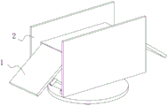
FIG. 1 is a schematic structural view of the present invention as a whole;
FIG. 2 is a cross-sectional view of the present invention;
FIG. 3 is a schematic structural diagram of the lifting device of the present invention;
FIG. 4 is a schematic structural view of the bottom of the base plate of the present invention;
FIG. 5 is a schematic view of the structure of the stabilizing device of the present invention;
FIG. 6 is a schematic view of the locking device of the present invention;
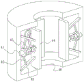
fig. 7 is a schematic structural diagram of the balancing apparatus of the present invention.
In the figure: the device comprises a machine body 1, a sealing plate 2, a lifting device 3, a balancing device 4, a screw rod 5, a stabilizing device 6, a top plate 10, an inclined plate 11, a connecting rod 13, a damping ring 14, an arc plate 15, a connecting pipe 16, a bottom plate 17, a clamping groove 18, a fixed disc 20, a locking device 21, a sleeve 22, an adjusting rod 23, a ball head 24, a bolt 30, a stop block 31, an elastic sheet 32, a hanging rod 33, an inserting rod 34, an air hole 35, an outer cover 40, an expansion link 41, a movable rod 42, a supporting rod 43, a clamping plate 44 and a compression spring 45.
Detailed Description
The technical solutions in the embodiments of the present invention will be clearly and completely described below with reference to the drawings in the embodiments of the present invention, and it is obvious that the described embodiments are only a part of the embodiments of the present invention, and not all of the embodiments. All other embodiments, which can be derived by a person skilled in the art from the embodiments given herein without making any creative effort, shall fall within the protection scope of the present invention.
Referring to fig. 1-7, the present invention provides a technical solution: a lifting machine based on efficient balance lifting comprises a machine body 1, wherein sealing plates 2 are movably connected to the front side and the back side of the machine body 1, the machine body 1 comprises a lifting device 3, a balance device 4 is arranged inside the lifting device 3, a screw rod 5 is movably connected to the inner surface of the balance device 4, a stabilizing device 6 is arranged outside the screw rod 5, and the stabilizing device 6 is located at the bottom of the balance device 4;
through setting up organism 1, when equipment uses, it is fixed with external ground contact with stabilising arrangement 6's lower surface, treat to fix stabilising arrangement 6 back, install screw rod 5 in proper order, balancing unit 4 and elevating gear 3, under elevating gear 3's effect, roof 10 up-and-down motion to this transportation of realization article, hydraulic pressure goes up and down to have reduced mechanical transmission's vibrations, treat that roof 10 moves to the assigned position after, screw rod 5 locks and dies, equipment remains static, traditional pure mechanical transport has been solved, the great problem of vibration range.
Through setting up elevating gear 3, when equipment uses, article move to the upper surface of roof 10 from swash plate 11, inject hydraulic oil to the inside of arc 15 through connecting pipe 16 this moment, the oil pressure forces roof 10 and bottom plate 17 distance increase, the crooked radian of arc 15 reduces, otherwise, roof 10 descends, at this in-process, the surface of roof 10 and arc 15 and the internal surface of closing plate 2 remain sealed laminating throughout, ensure that equipment can not take place to reveal when using, traditional hydraulic pressure transmission has been solved, the problem of equipment easy leakage.
The outer surface on connecting pipe 16 top and the internal surface fixed connection of arc 15, the internal surface of arc 15 is run through on the top of connecting pipe 16 to extend to the inside of arc 15, set up draw-in groove 18 in the wall of bottom plate 17 lower surface, the internal surface fixed connection of the surface of bottom plate 17 and closing plate 2, the internal surface sliding connection of closing plate 2 and surface of roof 10.
Through setting up damping ring 14, when roof 10 moves upwards, the high increase of equipment in the vertical direction, the focus of equipment moves upwards along screw rod 5, because damping ring 14 is in unsettled state, and its outer space is filled up by hydraulic oil, damping ring 14 at this moment receives connecting rod 13 vertical ascending resultant force, the ascending buoyancy of hydraulic oil and the vertical downward gravity combined action, keep static in the vertical direction, the focus of equipment descends along with the unsettled of damping ring 14, along with the work of equipment, the vibrations that external world or equipment self produced are transmitted to damping ring 14, the internal energy that the vibrations produced converts into the kinetic energy of damping ring 14 wobbling, improve the stability of equipment through consuming energy and lowering the focus, the problem that traditional jacking equipment is because the height is too high, easily topples is solved.
The stabilizing device 6 comprises a fixed disc 20, a locking device 21 is fixedly connected to the upper surface of the fixed disc 20, a sleeve 22 is arranged on the left side of the locking device 21, an adjusting rod 23 is connected to the inner surface of the sleeve 22 in a threaded manner, a ball head 24 is fixedly connected to the top end of the adjusting rod 23, the ball head 24 is fixedly mounted at the top end of the adjusting rod 23 and the bottom end of the sleeve 22, the outer surface of the ball head at the bottom end of the sleeve 22 is connected with the inner surface of the fixed disc 20 in a sliding manner, and the outer surface of the ball head at the top end of the adjusting rod 23 is rotatably connected with the lower surface of the bottom plate 17.
Through setting up stabilising arrangement 6, when equipment uses, because traditional jacking equipment is many perpendicular with equipment bottom contact surface, when the contact surface is non-horizontal, equipment can take place the slope, this moment, earlier fixed disk 20's lower surface is fixed with external stationary plane, bottom plate 17 can produce certain contained angle with fixed disk 20, sleeve 22's bottom and the top of adjusting pole 23 are under bulb 24's effect, take place relative rotation with bottom plate 17 and fixed disk 20, the internal surface of fixed disk 20 at this moment and screw rod 5's surface contactless, adjust pole 23 through rotating, make locking device 21 card go into the inside of draw-in groove 18, thereby ensure that elevating gear 3 keeps the level, the problem that traditional jacking equipment can only install at the horizontal plane has been solved.
The locking mechanism 21 comprises a bolt 30, a stop block 31 is fixedly connected to the outer surface of the bolt 30, an elastic sheet 32 is movably connected to the inner surface of the bolt 30, a hanging rod 33 is fixedly connected to the upper surface of the elastic sheet 32, an inserting rod 34 is rotatably connected to the outer surface of the hanging rod 33, the outer surfaces of the top ends of the inserting rod 34 and the hanging rod 33 are in sliding connection with the inner surface of the bolt 30, and an air hole 35 is formed in the wall of the bolt 30.
Through setting up locking device 21, when the upper surface of bolt 30 and draw-in groove 18 contact, along with deepening of bolt 30, the surface of dog 31 extrudees with the internal surface contact of draw-in groove 18, because the cross-section of dog 31 is the wedge, pressure crescent, bolt 30 extrudees the shrink, shell fragment 32 is crooked upwards, the volume of its upper surface reduces, because the upper surface of bolt 30 has laminated with draw-in groove 18, gas pocket 35 closes, high-pressure gas and shell fragment 32 jack-up plumbing 33 and inserted bar 34 upwards, locking device 21 blocks bottom plate 17, on the contrary, locking device 21 breaks away from, the dismouting of being convenient for of modular design, and the stability has also been improved simultaneously, the comparatively difficult problem of traditional elevating gear dismouting has been solved. Balancing unit 4 includes dustcoat 40, and the internal surface fixed connection of dustcoat 40 has telescopic link 41, and telescopic link 41's surface rotates and is connected with movable rod 42, and movable rod 42's bottom rotates and is connected with bracing piece 43, and the right-hand member of bracing piece 43 rotates and is connected with splint 44, the left surface of splint 44 and telescopic link 41's right-hand member fixed connection, telescopic link 41's surface swing joint has compression spring 45.
The supporting rods 43 are symmetrically arranged at the top and the bottom of the compression spring 45, the right end of the compression spring 45 is fixedly connected with the outer surface of the left side of the clamping plate 44, the outer surface of the right side of the clamping plate 44 is contacted with the outer surface of the screw rod 5, and the left end of the supporting rod 43 is slidably connected with the inner surface of the outer cover 40.
Through setting up balancing unit 4, when screw rod 5 moves, the surface on splint 44 right side slides with screw rod 5's surface, telescopic link 41 extrudees the left surface of splint 44 under compression spring 45's effect, compression spring 45 is in the power state of holding, when producing the clearance between screw rod 5 and the splint 44, compression spring 45 drives splint 44 and continues laminating screw rod 5, because bracing piece 43 and movable rod 42's length are fixed, the two takes place certain deflection, the left end of bracing piece 43 slides along the internal surface of dustcoat 40, block the internal surface of dustcoat 40 simultaneously, increase laminating effect, guarantee the leakproofness of equipment and screw rod 5's stability, the problem that traditional jacking equipment internal wear rocks and can influence equipment balance and availability factor is solved.
The lower surface of the bolt 30 is fixedly connected with the upper surface of the fixed disc 20, the air holes 35 are symmetrically formed in two sides of the vertical rod 33, the outer surfaces of the top ends of the vertical rod 33 and the insertion rod 34 are in sliding connection with the inner surface of the clamping groove 18, the inner surface of the clamping groove 18 is in sliding connection with the outer surface of the bolt 30, and the outer surface of the stop block 31 is in contact extrusion with the inner surface of the clamping groove.
A gap is formed between the inner surface of the fixed disc 20 and the outer surface of the inner surface of the screw rod 5, the bottom end of the screw rod 5 is connected with an external motor, and the lower surface of the fixed disc 20 is fixedly connected with the external ground.
The lower surface of the top plate 10 is rotatably connected with the top end of the screw rod 5, the outer surface of the screw rod 5 is rotatably connected with the inner surface of the bottom plate 17, the lower surface of the damping ring 14 is contacted with the upper surface of the bottom plate 17, and the upper surface of the bottom plate 17 is fixedly connected with the lower surface of the balancing device 4.
During the use, the lower surface of stabilising arrangement 6 and external ground contact are fixed, wait to fix stabilising arrangement 6 after, install screw rod 5, balancing unit 4 and elevating gear 3 in proper order, under elevating gear 3's effect, roof 10 up-and-down motion to this transportation of realization article, hydraulic pressure goes up and down to reduce mechanical transmission's vibrations, waits that roof 10 moves to the assigned position after, screw rod 5 locks, and equipment keeps static.
When the device is used, articles move to the upper surface of the top plate 10 from the inclined plate 11, at the moment, hydraulic oil is injected into the arc-shaped plate 15 through the connecting pipe 16, the distance between the top plate 10 and the bottom plate 17 is forced to be increased by the oil pressure, the bending radian of the arc-shaped plate 15 is reduced, otherwise, the top plate 10 descends, and in the process, the outer surfaces of the top plate 10 and the arc-shaped plate 15 are always in sealing fit with the inner surface of the sealing plate 2, so that the device is ensured not to leak when in use.
When the top plate 10 moves upwards, the height of the equipment in the vertical direction is increased, the gravity center of the equipment moves upwards along the screw rod 5, the damping ring 14 is in a suspension state, the outer space of the damping ring is filled with hydraulic oil, the damping ring 14 at the moment is kept static in the vertical direction under the combined action of vertical upwards resultant force of the connecting rod 13, upward buoyancy force of the hydraulic oil and vertical downwards gravity, the gravity center of the equipment descends along with the suspension of the damping ring 14, vibration generated by the outside or the equipment per se is transmitted to the damping ring 14 along with the operation of the equipment, internal energy generated by the vibration is converted into kinetic energy of the swinging of the damping ring 14, and the stability of the equipment is improved by consuming the energy and reducing the gravity center.
When equipment uses, because traditional jacking equipment is many perpendicular with equipment bottom contact surface, when the contact surface is non-horizontal, equipment can take place the slope, at this moment, earlier the lower surface of fixed disk 20 is fixed with external stationary plane, bottom plate 17 can produce certain contained angle with fixed disk 20, the bottom of sleeve 22 and the top of adjusting pole 23 are under bulb 24's effect, take place relative rotation with bottom plate 17 and fixed disk 20, the internal surface of fixed disk 20 at this moment and the surface contactless of screw rod 5, adjust pole 23 through rotating, make locking device 21 card go into the inside of draw-in groove 18, thereby ensure that elevating gear 3 keeps the level.
When the upper surface of the bolt 30 contacts with the slot 18, along with the depth of the bolt 30, the outer surface of the stop block 31 contacts and extrudes with the inner surface of the slot 18, because the section of the stop block 31 is wedge-shaped, the pressure is gradually increased, the bolt 30 extrudes and contracts, the elastic sheet 32 bends upwards, the volume of the upper surface of the stop block is reduced, because the upper surface of the bolt 30 is attached to the slot 18, the air hole 35 is closed, the high-pressure gas and the elastic sheet 32 jack up the hanging rod 33 and the inserting rod 34 upwards, the locking device 21 locks the bottom plate 17, otherwise, the locking device 21 is separated, the modularized design facilitates the disassembly and assembly, and meanwhile, the stability is also improved.
When the screw rod 5 moves, the outer surface on the right side of the clamping plate 44 slides with the outer surface of the screw rod 5, the telescopic rod 41 extrudes the outer surface on the left side of the clamping plate 44 under the action of the compression spring 45, the compression spring 45 is in a force accumulation state, when a gap is generated between the screw rod 5 and the clamping plate 44, the compression spring 45 drives the clamping plate 44 to continuously attach to the screw rod 5, the supporting rod 43 and the movable rod 42 are fixed in length and deflect to a certain degree, the left end of the supporting rod 43 slides along the inner surface of the outer cover 40, the inner surface of the outer cover 40 is clamped at the same time, the attaching effect is increased, and the sealing performance of the equipment and the stability of the screw rod 5 are ensured.
It is noted that, herein, relational terms such as first and second, and the like may be used solely to distinguish one entity or action from another entity or action without necessarily requiring or implying any actual such relationship or order between such entities or actions. Also, the terms "comprises," "comprising," or any other variation thereof, are intended to cover a non-exclusive inclusion, such that a process, method, article, or apparatus that comprises a list of elements does not include only those elements but may include other elements not expressly listed or inherent to such process, method, article, or apparatus. The term "comprising", without further limitation, means that the element so defined is not excluded from the group consisting of additional identical elements in the process, method, article, or apparatus that comprises the element.
Although embodiments of the present invention have been shown and described, it will be appreciated by those skilled in the art that changes, modifications, substitutions and alterations can be made in these embodiments without departing from the principles and spirit of the invention, the scope of which is defined in the appended claims and their equivalents.
Claims (8)
1. The utility model provides a machine of lifting based on high-efficient balanced lifting, includes organism (1), its characterized in that: the front and the back of the machine body (1) are movably connected with sealing plates (2), the machine body (1) comprises a lifting device (3), a balancing device (4) is arranged inside the lifting device (3), a screw rod (5) is movably connected to the inner surface of the balancing device (4), a stabilizing device (6) is arranged outside the screw rod (5), and the stabilizing device (6) is positioned at the bottom of the balancing device (4);
the lifting device (3) comprises a top plate (10), the outer surfaces of the left side and the right side of the top plate (10) are rotatably connected with inclined plates (11), the lower surface of the top plate (10) is rotatably connected with a connecting rod (13), the bottom end of the connecting rod (13) is movably connected with a damping ring (14), the left side and the right side of the damping ring (14) are provided with arc plates (15), the upper surface of each arc plate (15) is movably connected with the lower surface of the top plate (10), the lower surface of each arc plate (15) is movably connected with a bottom plate (17), and the top of each bottom plate (17) is provided with a connecting pipe (16);
the outer surface on the top end of the connecting pipe (16) is fixedly connected with the inner surface of the arc-shaped plate (15), the top end of the connecting pipe (16) penetrates through the inner surface of the arc-shaped plate (15) and extends to the inside of the arc-shaped plate (15), a clamping groove (18) is formed in the wall of the lower surface of the bottom plate (17), the outer surface of the bottom plate (17) is fixedly connected with the inner surface of the sealing plate (2), and the inner surface of the sealing plate (2) is connected with the outer surface of the top plate (10) in a sliding mode.
2. The efficient balance lifting based lifting machine as claimed in claim 1, wherein: stabilising arrangement (6) are including fixed disk (20), the last fixed surface of fixed disk (20) is connected with locking device (21), the left side of locking device (21) is provided with sleeve (22), the internal surface threaded connection of sleeve (22) has regulation pole (23), the top fixedly connected with bulb (24) of adjusting pole (23), bulb (24) fixed mounting is in the top of adjusting pole (23) and the bottom of sleeve (22), the surface of the bulb of sleeve (22) bottom and the internal surface sliding connection of fixed disk (20), the surface of the bulb of adjusting pole (23) top is connected with the lower surface rotation of bottom plate (17).
3. The efficient balance lifting based lifting machine as claimed in claim 2, wherein: locking device (21) includes bolt (30), the external fixed surface of bolt (30) is connected with dog (31), the internal surface swing joint of bolt (30) has shell fragment (32), the last fixed surface of shell fragment (32) is connected with down-hanging rod (33), the surface of down-hanging rod (33) rotates and is connected with inserted bar (34), the surface on inserted bar (34) and down-hanging rod (33) top and the internal surface sliding connection of bolt (30), open in the wall of bolt (30) and be equipped with gas pocket (35).
4. The efficient balance lifting based lifting machine as claimed in claim 1, wherein: balancing unit (4) include dustcoat (40), the internal surface fixedly connected with telescopic link (41) of dustcoat (40), the surface of telescopic link (41) rotates and is connected with movable rod (42), the bottom of movable rod (42) rotates and is connected with bracing piece (43), the right-hand member of bracing piece (43) rotates and is connected with splint (44), the left surface of splint (44) and the right-hand member fixed connection of telescopic link (41), the surface swing joint of telescopic link (41) has compression spring (45).
5. The efficient balance lifting based lifting machine as claimed in claim 4, wherein: bracing piece (43) symmetry is installed at the top and the bottom of compression spring (45), the right-hand member of compression spring (45) and the left surface fixed connection of splint (44), the surface on splint (44) right side contacts with the surface of screw rod (5), the left end of bracing piece (43) and the internal surface sliding connection of dustcoat (40).
6. The efficient balance lifting based lifting machine as claimed in claim 3, wherein: the lower surface of bolt (30) is connected with the upper surface fixed of fixed disk (20), the both sides of hanging down pole (33) are seted up to gas pocket (35) symmetry, the surface on hanging down pole (33) and inserted bar (34) top and the internal surface sliding connection of draw-in groove (18), the internal surface of draw-in groove (18) and the surface sliding connection of bolt (30), the surface of dog (31) and the internal surface contact extrusion of draw-in groove.
7. The efficient balance lifting based lifting machine as claimed in claim 2, wherein: a gap exists between the inner surface of the fixed disc (20) and the outer surface of the screw rod (5), the bottom end of the screw rod (5) is connected with an external motor, and the lower surface of the fixed disc (20) is fixedly connected with the external ground.
8. The efficient balance lifting based lifting machine as claimed in claim 1, wherein: the lower surface of roof (10) is rotated with the top of screw rod (5) and is connected, the surface of screw rod (5) is rotated with the internal surface of bottom plate (17) and is connected, the lower surface of damping ring (14) contacts with the upper surface of bottom plate (17), the upper surface of bottom plate (17) and the lower surface fixed connection of balancing unit (4).
Priority Applications (1)
| Application Number | Priority Date | Filing Date | Title |
|---|---|---|---|
| CN202111253418.XA CN113697719B (en) | 2021-10-27 | 2021-10-27 | Machine of lifting based on high-efficient balanced lifting |
Applications Claiming Priority (1)
| Application Number | Priority Date | Filing Date | Title |
|---|---|---|---|
| CN202111253418.XA CN113697719B (en) | 2021-10-27 | 2021-10-27 | Machine of lifting based on high-efficient balanced lifting |
Publications (2)
| Publication Number | Publication Date |
|---|---|
| CN113697719A CN113697719A (en) | 2021-11-26 |
| CN113697719B true CN113697719B (en) | 2021-12-28 |
Family
ID=78647062
Family Applications (1)
| Application Number | Title | Priority Date | Filing Date |
|---|---|---|---|
| CN202111253418.XA Active CN113697719B (en) | 2021-10-27 | 2021-10-27 | Machine of lifting based on high-efficient balanced lifting |
Country Status (1)
| Country | Link |
|---|---|
| CN (1) | CN113697719B (en) |
Families Citing this family (1)
| Publication number | Priority date | Publication date | Assignee | Title |
|---|---|---|---|---|
| CN114835053B (en) * | 2022-04-18 | 2022-11-01 | 大汉科技股份有限公司 | Building automatic lifting machine |
Citations (4)
| Publication number | Priority date | Publication date | Assignee | Title |
|---|---|---|---|---|
| SU521215A1 (en) * | 1974-02-07 | 1976-07-15 | Предприятие П/Я А-3590 | Screw jack |
| CN101171197A (en) * | 2005-05-12 | 2008-04-30 | 空中客车法国公司 | Sling device for a piece with force compensation and hoisting system comprising the same |
| CN202492337U (en) * | 2012-03-10 | 2012-10-17 | 浙江吉鑫祥叉车制造有限公司 | Outward-swing door of storage battery counter balanced forklift |
| CN104495699A (en) * | 2014-12-19 | 2015-04-08 | 浙江德盛铁路器材股份有限公司 | Self-balancing flexible-steering engineering vehicle |
-
2021
- 2021-10-27 CN CN202111253418.XA patent/CN113697719B/en active Active
Patent Citations (4)
| Publication number | Priority date | Publication date | Assignee | Title |
|---|---|---|---|---|
| SU521215A1 (en) * | 1974-02-07 | 1976-07-15 | Предприятие П/Я А-3590 | Screw jack |
| CN101171197A (en) * | 2005-05-12 | 2008-04-30 | 空中客车法国公司 | Sling device for a piece with force compensation and hoisting system comprising the same |
| CN202492337U (en) * | 2012-03-10 | 2012-10-17 | 浙江吉鑫祥叉车制造有限公司 | Outward-swing door of storage battery counter balanced forklift |
| CN104495699A (en) * | 2014-12-19 | 2015-04-08 | 浙江德盛铁路器材股份有限公司 | Self-balancing flexible-steering engineering vehicle |
Also Published As
| Publication number | Publication date |
|---|---|
| CN113697719A (en) | 2021-11-26 |
Similar Documents
| Publication | Publication Date | Title |
|---|---|---|
| CN113697719B (en) | Machine of lifting based on high-efficient balanced lifting | |
| CA2808602A1 (en) | Tower-type double-chain belt pumping unit | |
| CN217977941U (en) | Pipeline strutting arrangement is used in water conservancy and hydropower construction | |
| CN210118040U (en) | Large-scale vacuum chamber ground movable type opening and closing gate structure | |
| CN217974286U (en) | Jacket supporting structure for offshore platform expansion | |
| CN213271873U (en) | Jacking mechanism of module area sorting machine | |
| CN216532128U (en) | Installation device for mobile electrical equipment of ocean platform | |
| CN216640600U (en) | Construction underground structure is built in room | |
| CN201381840Y (en) | Large-size long-stroke heavy-load energy-saving oil pumping unit | |
| CN211080644U (en) | Building reinforcing and damping device | |
| CN215443374U (en) | Anti-seismic steel structure support for building | |
| CN215798225U (en) | Crane installation and maintenance safety platform | |
| CN214219633U (en) | Assembled prestressing force bamboo joint stake | |
| CN211971622U (en) | Lifting mechanism of balance jack for assembling mining equipment | |
| CN114321650A (en) | Load base is used in hydraulic turbine installation | |
| CN101863431A (en) | Stepless mechanical lifting gear | |
| CN202031549U (en) | Pneumatic-balance hydraulic pumping unit for offshore platform | |
| CN113417609B (en) | Vertical oil pumping machine | |
| CN214838289U (en) | Wall-mounted box | |
| CN219993680U (en) | Beam-free hydraulic pumping unit | |
| CN219033208U (en) | Auxiliary supporting device of inclined pile driver and large-inclination-angle inclined pile driver | |
| CN215669048U (en) | Device for preventing construction platform lateral sliding | |
| CN212802268U (en) | Prefabricated column of prefabricated building | |
| CN216403496U (en) | Mounting structure of elevator inverter | |
| CN114232969B (en) | Building construction protection frame |
Legal Events
| Date | Code | Title | Description |
|---|---|---|---|
| PB01 | Publication | ||
| PB01 | Publication | ||
| SE01 | Entry into force of request for substantive examination | ||
| SE01 | Entry into force of request for substantive examination | ||
| GR01 | Patent grant | ||
| GR01 | Patent grant |