CN113687601B - Automatic adjustment method of equipment and intelligent adjustment device applying same - Google Patents
Automatic adjustment method of equipment and intelligent adjustment device applying same Download PDFInfo
- Publication number
- CN113687601B CN113687601B CN202010418228.8A CN202010418228A CN113687601B CN 113687601 B CN113687601 B CN 113687601B CN 202010418228 A CN202010418228 A CN 202010418228A CN 113687601 B CN113687601 B CN 113687601B
- Authority
- CN
- China
- Prior art keywords
- clear
- pane
- intelligent
- pictures
- template
- Prior art date
- Legal status (The legal status is an assumption and is not a legal conclusion. Google has not performed a legal analysis and makes no representation as to the accuracy of the status listed.)
- Active
Links
Images


Classifications
-
- G—PHYSICS
- G06—COMPUTING OR CALCULATING; COUNTING
- G06T—IMAGE DATA PROCESSING OR GENERATION, IN GENERAL
- G06T1/00—General purpose image data processing
- G06T1/0014—Image feed-back for automatic industrial control, e.g. robot with camera
-
- G—PHYSICS
- G05—CONTROLLING; REGULATING
- G05B—CONTROL OR REGULATING SYSTEMS IN GENERAL; FUNCTIONAL ELEMENTS OF SUCH SYSTEMS; MONITORING OR TESTING ARRANGEMENTS FOR SUCH SYSTEMS OR ELEMENTS
- G05B19/00—Programme-control systems
- G05B19/02—Programme-control systems electric
- G05B19/04—Programme control other than numerical control, i.e. in sequence controllers or logic controllers
- G05B19/042—Programme control other than numerical control, i.e. in sequence controllers or logic controllers using digital processors
- G05B19/0426—Programming the control sequence
-
- G—PHYSICS
- G06—COMPUTING OR CALCULATING; COUNTING
- G06T—IMAGE DATA PROCESSING OR GENERATION, IN GENERAL
- G06T7/00—Image analysis
- G06T7/0002—Inspection of images, e.g. flaw detection
- G06T7/0004—Industrial image inspection
-
- G—PHYSICS
- G06—COMPUTING OR CALCULATING; COUNTING
- G06T—IMAGE DATA PROCESSING OR GENERATION, IN GENERAL
- G06T7/00—Image analysis
- G06T7/20—Analysis of motion
-
- G—PHYSICS
- G06—COMPUTING OR CALCULATING; COUNTING
- G06V—IMAGE OR VIDEO RECOGNITION OR UNDERSTANDING
- G06V30/00—Character recognition; Recognising digital ink; Document-oriented image-based pattern recognition
- G06V30/10—Character recognition
- G06V30/14—Image acquisition
-
- G—PHYSICS
- G09—EDUCATION; CRYPTOGRAPHY; DISPLAY; ADVERTISING; SEALS
- G09G—ARRANGEMENTS OR CIRCUITS FOR CONTROL OF INDICATING DEVICES USING STATIC MEANS TO PRESENT VARIABLE INFORMATION
- G09G3/00—Control arrangements or circuits, of interest only in connection with visual indicators other than cathode-ray tubes
- G09G3/006—Electronic inspection or testing of displays and display drivers, e.g. of LED or LCD displays
-
- G—PHYSICS
- G06—COMPUTING OR CALCULATING; COUNTING
- G06T—IMAGE DATA PROCESSING OR GENERATION, IN GENERAL
- G06T2200/00—Indexing scheme for image data processing or generation, in general
- G06T2200/24—Indexing scheme for image data processing or generation, in general involving graphical user interfaces [GUIs]
-
- G—PHYSICS
- G06—COMPUTING OR CALCULATING; COUNTING
- G06T—IMAGE DATA PROCESSING OR GENERATION, IN GENERAL
- G06T2207/00—Indexing scheme for image analysis or image enhancement
- G06T2207/10—Image acquisition modality
- G06T2207/10056—Microscopic image
- G06T2207/10061—Microscopic image from scanning electron microscope
-
- G—PHYSICS
- G06—COMPUTING OR CALCULATING; COUNTING
- G06T—IMAGE DATA PROCESSING OR GENERATION, IN GENERAL
- G06T2207/00—Indexing scheme for image analysis or image enhancement
- G06T2207/30—Subject of image; Context of image processing
- G06T2207/30108—Industrial image inspection
- G06T2207/30148—Semiconductor; IC; Wafer
-
- G—PHYSICS
- G09—EDUCATION; CRYPTOGRAPHY; DISPLAY; ADVERTISING; SEALS
- G09G—ARRANGEMENTS OR CIRCUITS FOR CONTROL OF INDICATING DEVICES USING STATIC MEANS TO PRESENT VARIABLE INFORMATION
- G09G2320/00—Control of display operating conditions
- G09G2320/02—Improving the quality of display appearance
- G09G2320/0247—Flicker reduction other than flicker reduction circuits used for single beam cathode-ray tubes
-
- G—PHYSICS
- G09—EDUCATION; CRYPTOGRAPHY; DISPLAY; ADVERTISING; SEALS
- G09G—ARRANGEMENTS OR CIRCUITS FOR CONTROL OF INDICATING DEVICES USING STATIC MEANS TO PRESENT VARIABLE INFORMATION
- G09G2354/00—Aspects of interface with display user
-
- G—PHYSICS
- G09—EDUCATION; CRYPTOGRAPHY; DISPLAY; ADVERTISING; SEALS
- G09G—ARRANGEMENTS OR CIRCUITS FOR CONTROL OF INDICATING DEVICES USING STATIC MEANS TO PRESENT VARIABLE INFORMATION
- G09G2380/00—Specific applications
Landscapes
- Engineering & Computer Science (AREA)
- Physics & Mathematics (AREA)
- General Physics & Mathematics (AREA)
- Theoretical Computer Science (AREA)
- Computer Vision & Pattern Recognition (AREA)
- Multimedia (AREA)
- Automation & Control Theory (AREA)
- Robotics (AREA)
- Quality & Reliability (AREA)
- Computer Hardware Design (AREA)
- Analysing Materials By The Use Of Radiation (AREA)
- Image Processing (AREA)
- Image Analysis (AREA)
Abstract
Description
技术领域technical field
本发明涉及一种自动控制方法及应用其的电子装置,且特别涉及一种设备的自动调整方法及应用其的智能调整装置。The invention relates to an automatic control method and an electronic device using the same, and in particular to an automatic adjustment method of equipment and an intelligent adjustment device using the same.
背景技术Background technique
随着半导体技术的发展,测量设备与工艺设备的操作也越趋复杂。在测量设备与工艺设备的操作过程中,操作人员必须相当熟悉使用者界面的流程,在操作画面所显示的信息下,进行对应的操作。每一测量设备与工艺设备都需要有操作人员随时待命进行监控,因此必须耗费大量人力来对测量设备与工艺设备进行操作。尤其是在扫描电子显微镜、黄光机台等设备可能会有画面闪灭及晃动的情况,更需要通过人工辨识画面稳定度来确认设备的参数是否校准。With the development of semiconductor technology, the operation of measurement equipment and process equipment is becoming more and more complex. During the operation of measuring equipment and process equipment, operators must be quite familiar with the flow of the user interface, and perform corresponding operations under the information displayed on the operation screen. Every measuring device and process device needs to be monitored by an operator on standby at any time, so a lot of manpower must be consumed to operate the measuring device and process device. Especially in scanning electron microscopes, yellow light machines and other equipment, the screen may flicker and shake, and it is necessary to manually identify the stability of the screen to confirm whether the parameters of the equipment are calibrated.
研究人员正致力发展以软件机器人对测量设备与工艺设备进行操作的技术。然而,软件机器人对于画面稳定度的辨识能力相当不足,而有相当程度的困难度,形成了长久以来的技术瓶颈。Researchers are working to develop techniques for manipulating measurement and process equipment with software robots. However, the ability of software robots to identify the image stability is quite insufficient, and there is a considerable degree of difficulty, which has formed a long-standing technical bottleneck.
发明内容Contents of the invention
本发明涉及一种设备的自动调整方法及应用其的智能调整装置,其利用像素变异数进行分析,使得软件机器人也能够对画面稳定度进行辨识,进而自动调整设备的参数。The invention relates to an automatic adjustment method of equipment and an intelligent adjustment device using the same, which uses pixel variation to analyze, so that software robots can also identify the stability of the picture, and then automatically adjust the parameters of the equipment.
根据本发明的第一方面,提出一种设备的自动调整方法。设备的自动调整方法包括以下步骤。在一起始期间中获得设备的一模板画面。在一窗格中获得数个清晰画面。模板画面及此些清晰画面各具有一像素变异数。模板画面的像素变异数为起始期间中最大者。各个清晰画面的像素变异数大于一临界值。比对各个清晰画面与模板画面,以各别获得一偏移量。计算此些偏移量的一统计值。调整设备的一参数,以降低统计值。According to a first aspect of the present invention, a method for automatic adjustment of equipment is proposed. The automatic adjustment method of the equipment includes the following steps. A template picture of the device is obtained during the initial session. Get several sharp images in one pane. The template frame and the clear frames each have a pixel variance. The number of pixel variations of the template picture is the largest in the initial period. The number of pixel variations of each clear frame is larger than a threshold value. Each clear frame is compared with the template frame to obtain an offset respectively. Compute a statistic of these offsets. Adjust a parameter of the device to reduce the statistical value.
根据本发明的第二方面,提出一种智能调整装置。智能调整装置用以自动调整一设备。智能调整装置包括一通信单元、一画面分析单元及一远端控制单元。通信单元用以远端连线至设备。画面分析单元包括一模板分析器、一清晰度分析器、一偏移量计算器及一统计器。模板分析器用以在一起始期间获得设备的一模板画面。清晰度分析器用以在一窗格中获得数个清晰画面。模板画面及此些清晰画面各具有一像素变异数。模板画面的像素变异数为起始期间中最大者,各个清晰画面的像素变异数大于一临界值。偏移量计算器用以比对各个清晰画面与模板画面,以各别获得一偏移量。统计器用以计算此些偏移量的一统计值。远端控制单元包括一调整器。调整器用以自动调整设备的一参数,以降低统计值。According to the second aspect of the present invention, an intelligent adjustment device is proposed. The intelligent adjustment device is used for automatic adjustment of a device. The intelligent adjustment device includes a communication unit, a picture analysis unit and a remote control unit. The communication unit is used for remote connection to the device. The frame analysis unit includes a template analyzer, a resolution analyzer, an offset calculator and a statistician. The template analyzer is used to obtain a template screen of the device during initialization. The Sharpness Analyzer is used to get several clear pictures in one pane. The template frame and the clear frames each have a pixel variance. The pixel variance of the template frame is the largest in the initial period, and the pixel variance of each clear frame is greater than a critical value. The offset calculator is used for comparing each clear frame with the template frame to obtain an offset respectively. The statistician is used to calculate a statistical value of the offsets. The remote control unit includes an adjuster. The adjuster is used to automatically adjust a parameter of the device to reduce the statistical value.
为了对本发明的上述及其他方面有更佳的了解,下文特举实施例,并配合附图详细说明如下:In order to have a better understanding of the above-mentioned and other aspects of the present invention, the following specific embodiments are described in detail with reference to the accompanying drawings:
附图说明Description of drawings
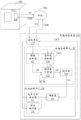
图1绘示根据一实施例的智能调整装置的示意图。FIG. 1 is a schematic diagram of an intelligent adjustment device according to an embodiment.
图2绘示根据一实施例的种设备的自动调整方法的流程图。FIG. 2 is a flowchart of a method for automatically adjusting a device according to an embodiment.
图3示例说明根据一实施例的步骤S110的示意图。FIG. 3 illustrates a schematic diagram of step S110 according to an embodiment.
图4绘示根据一实施例的一模板画面的示意图。FIG. 4 is a schematic diagram of a template screen according to an embodiment.
图5示例说明根据一实施例的步骤S120的示意图。FIG. 5 illustrates a schematic diagram of step S120 according to an embodiment.
图6示例说明步骤S130的示意图。FIG. 6 illustrates a schematic diagram of step S130.
图7示例说明在参数未正确调整时的偏移量的分布图。Figure 7 illustrates a graph of the distribution of offsets when the parameters are not adjusted correctly.
图8示例说明在参数已正确调整时的偏移量的分布图。Figure 8 illustrates a graph of the distribution of offsets when the parameters are correctly tuned.
图9绘示参数设定与平均值的分布曲线。FIG. 9 shows distribution curves of parameter settings and mean values.
图10绘示参数设定与最大值的分布曲线。FIG. 10 shows distribution curves of parameter settings and maximum values.
具体实施方式Detailed ways
请参照图1,其绘示根据一实施例的智能调整装置100的示意图。智能调整装置100例如是一服务器、一丛集计算系统(cluster computing system)、或一计算机。智能调整装置100用以对设备900进行操控。设备900例如是工艺设备或测量设备(例如是临界尺寸扫描电子显微镜)。设备900具有一使用者界面(user interface)910。使用者界面910例如是一触控屏幕。操作人员可以在使用者界面910所显示的操作画面F9上点选指令方块,以对设备900下达调整指令CM9。在本实施例中,智能调整装置100能够对操作画面F9进行远端分析,并依据分析结果直接下达调整指令CM9,而不需要操作人员站在设备900前面操作。Please refer to FIG. 1 , which shows a schematic diagram of an intelligent adjustment device 100 according to an embodiment. The intelligent adjustment device 100 is, for example, a server, a cluster computing system, or a computer. The intelligent adjustment device 100 is used to control the
请参照图1,智能调整装置100包括一通信单元110、一画面分析单元120及一远端控制单元130。通信单元110用以通过网络700远端连线至设备900。通信单元110例如是一无线通信模块、或一有线网络模块。画面分析单元120包括一模板分析器121、一清晰度分析器122、一偏移量计算器123及一统计器124。画面分析单元120用以对画面进行分析,以获得能够代表画面稳定度的统计值SV。远端控制单元130包括一光学文字辨识器131、一图案辨识器132及一调整器133。远端控制单元130用以对设备900进行调整,以提高画面稳定度。画面分析单元120及远端控制单元130例如是一电路、一芯片、一电路板或存储数组程序代码的存储装置。以下搭配一流程图详细说明智能调整装置100的运作方式。Please refer to FIG. 1 , the smart adjustment device 100 includes a
请参照图2,其绘示根据一实施例的种设备900的自动调整方法的流程图。首先,请参照图3及图4,图3示例说明根据一实施例的步骤S110的示意图,图4绘示根据一实施例的一模板画面F0的示意图。在步骤S110中,模板分析器121在一起始期间P0获得设备900的模板画面F0。在一实施例中,起始期间P0为第一秒期间。在起始期间P0例如是取得一开始的25张、或60张画面。此些画面可以是使用者界面910的整个操作画面F9,或者是操作画面F9中的某一个视窗。此视窗所显示的例如是用以校准的图案。在起始期间P0中的每一张画面均具有一像素变异数。模板画面F0的像素变异数为起始期间P0中最大者。一般来说,像素深浅差异越明显时,越能够呈现出清晰的线条。因此,本公开选用像素变异数最大者作为模板画面F0。清晰的模板画面F0可以用来比对出后续的画面是否有晃动。Please refer to FIG. 2 , which shows a flowchart of an automatic adjustment method of the
接着,请参照图5,其示例说明根据一实施例的步骤S120的示意图。由于画面会有闪灭的情况,因此无法将所有的画面均纳入考量。在步骤S120中,清晰度分析器122在一窗格WD中获得部分的数个清晰画面F1。窗格WD例如是5秒、10秒、20秒的区间。窗格WD不一定为起始的时间,可以是中间的任何时间。窗格WD中的每一画面皆具有像素变异数。像素变异数大于一临界值TH者,定义为清晰画面F1。临界值TH例如为窗格WD的像素变异数的2/3分位数、1/2分位数、1/3分位数或一预定值。画面随着时间连续提取时,窗格WD可以移动,以更新临界值TH并更新清晰画面F1。举例来说,例如是每新增一张画面,窗格WD就被移动一个画面,以纳入新增的画面,并移除一张画面。Next, please refer to FIG. 5 , which illustrates a schematic diagram of step S120 according to an embodiment. Due to the flickering of the screen, not all screens can be taken into consideration. In step S120 , the
接着,请参照图6,其示例说明步骤S130的示意图。在步骤S130中,偏移量计算器123比对各个清晰画面F1与模板画面F0,以各别获得一偏移量OS。在此步骤中,偏移量计算器123定义出清晰画面F1的比对框线B1、及模板画面F0的比对框线B0。比对框线B1与比对框线B0之内的图案近似。比对框线B1与比对框线B0的位移即为偏移量OS。一般来说,若画面稳定度不高,则会使偏移量OS的变异程度很大。Next, please refer to FIG. 6 , which illustrates a schematic diagram of step S130 . In step S130 , the offset
然后,在步骤S140中,统计器124计算这些偏移量OS的一统计值SV。统计值SV例如是平均值或最大值。统计值SV足以代表设备900在此参数设定下的画面稳定度情况。Then, in step S140 , the
接着,在步骤S150中,远端控制单元130的调整器133输出调整指令CM9,来自动调整设备900的参数,以降低统计值SV。请参照图7,其示例说明在参数未正确调整时的偏移量OS的分布图。如图7所示,在未正确调整设备900的参数时,偏移量OS的变化较大。Next, in step S150 , the
请参照图8,其示例说明在参数已正确调整时的偏移量OS的分布图。如图8所示,在正确调整设备900的参数后,偏移量OS的变化明显变小。图8所采的参数设定明显优于图7所采的参数设定。Please refer to FIG. 8 , which illustrates the distribution of the offset OS when the parameters are correctly adjusted. As shown in FIG. 8 , after the parameters of the
请参照图9,其绘示参数设定与平均值的分布曲线。参数设定为刻度a、刻度b时,平均值Eb低于平均值Ea。请参照图10,其绘示参数设定与最大值的分布曲线。参数设定为刻度a、刻度b时,最大值Mb低于最大值Ma。从图9与图10的观察可以得知,最佳的参数设定为平均值(或最大值)的最低点。因此,调整器133在增加参数时,即可判断平均值(或最大值)是否下降。若有,则继续增加参数;若没有,则反向降低参数。同理,调整器133在降低参数时,即可判断平均值(或最大值)是否下降。若有,则继续降低参数;若没有,则反向增加参数。重复上述动作,直到抵达平均值(或最大值)的分布曲线的最低点为止。Please refer to FIG. 9 , which shows distribution curves of parameter settings and average values. When the parameters are set to scale a and scale b, the average value Eb is lower than the average value Ea. Please refer to FIG. 10 , which shows distribution curves of parameter settings and maximum values. When the parameter is set to scale a and scale b, the maximum value Mb is lower than the maximum value Ma. It can be seen from the observations in FIG. 9 and FIG. 10 that the optimal parameter setting is the lowest point of the average value (or maximum value). Therefore, when the
调整器133执行步骤S150时,需要光学文字辨识器131及图案辨识器132的辅助。光学文字辨识器131辨识设备900的使用者界面910的文字。图案辨识器132辨识设备900的使用者界面910的按钮。辨识出使用者界面910的文字或按钮后,调整器133可以输出调整指令CM9去点选使用者界面910上的按钮,以自动调整设备900的参数。When the
根据上述实施例,软件机器人也能够对画面稳定度进行辨识,进而自动调整设备900的参数。According to the above-mentioned embodiment, the software robot can also identify the stability of the image, and then automatically adjust the parameters of the
综上所述,虽然本发明已以实施例公开如上,然其并非用以限定本发明。本发明所属技术领域中的技术人员在不脱离本发明的精神和范围内,当可作各种的更动与润饰。因此,本发明的保护范围当视所附的权利要求所界定者为准。To sum up, although the present invention has been disclosed by the above embodiments, it is not intended to limit the present invention. Those skilled in the art to which the present invention belongs may make various changes and modifications without departing from the spirit and scope of the present invention. Therefore, the scope of protection of the present invention should be defined by the appended claims.
Claims (18)
Priority Applications (2)
| Application Number | Priority Date | Filing Date | Title |
|---|---|---|---|
| CN202010418228.8A CN113687601B (en) | 2020-05-18 | 2020-05-18 | Automatic adjustment method of equipment and intelligent adjustment device applying same |
| US16/906,263 US11403728B2 (en) | 2020-05-18 | 2020-06-19 | Automatic adjusting method for equipment and smart adjusting device using the same |
Applications Claiming Priority (1)
| Application Number | Priority Date | Filing Date | Title |
|---|---|---|---|
| CN202010418228.8A CN113687601B (en) | 2020-05-18 | 2020-05-18 | Automatic adjustment method of equipment and intelligent adjustment device applying same |
Publications (2)
| Publication Number | Publication Date |
|---|---|
| CN113687601A CN113687601A (en) | 2021-11-23 |
| CN113687601B true CN113687601B (en) | 2022-11-29 |
Family
ID=78512660
Family Applications (1)
| Application Number | Title | Priority Date | Filing Date |
|---|---|---|---|
| CN202010418228.8A Active CN113687601B (en) | 2020-05-18 | 2020-05-18 | Automatic adjustment method of equipment and intelligent adjustment device applying same |
Country Status (2)
| Country | Link |
|---|---|
| US (1) | US11403728B2 (en) |
| CN (1) | CN113687601B (en) |
Families Citing this family (3)
| Publication number | Priority date | Publication date | Assignee | Title |
|---|---|---|---|---|
| US11513886B2 (en) * | 2021-03-11 | 2022-11-29 | UiPath, Inc. | System and computer-implemented method for managing robotic process automation (RPA) robots |
| CN114222184B (en) * | 2022-01-27 | 2023-08-15 | 英华达(上海)科技有限公司 | Multimedia playing control method, system, equipment and medium based on motion state |
| KR102810427B1 (en) * | 2022-04-12 | 2025-05-23 | (주)심플랫폼 | A System and Method for Collecting Equipment and Facility Data using RPA |
Citations (2)
| Publication number | Priority date | Publication date | Assignee | Title |
|---|---|---|---|---|
| CN1365231A (en) * | 2001-01-11 | 2002-08-21 | 金宝电子工业股份有限公司 | Method for image horizontal regulation |
| CN110769216A (en) * | 2018-08-28 | 2020-02-07 | 成都极米科技股份有限公司 | Projector hot focus-running judging method and projector |
Family Cites Families (15)
| Publication number | Priority date | Publication date | Assignee | Title |
|---|---|---|---|---|
| US5809171A (en) * | 1996-01-05 | 1998-09-15 | Mcdonnell Douglas Corporation | Image processing method and apparatus for correlating a test image with a template |
| US6959118B2 (en) * | 2001-03-26 | 2005-10-25 | Dynapel Systems, Inc. | Method and system for the estimation and compensation of brightness changes for optical flow calculations |
| CN100477718C (en) * | 2003-09-10 | 2009-04-08 | 精工爱普生株式会社 | Output image data generation device and output image data generation method |
| US7421143B2 (en) * | 2004-06-01 | 2008-09-02 | Xerox Corporation | Systems and methods for optimal dynamic range adjustment of scanned images |
| WO2007042044A1 (en) * | 2005-10-14 | 2007-04-19 | Unisense Fertilitech A/S | Determination of a change in a cell population |
| JP4638800B2 (en) * | 2005-10-27 | 2011-02-23 | 株式会社日立ハイテクノロジーズ | Machine difference management system and method in scanning electron microscope apparatus |
| JP4920268B2 (en) | 2006-02-23 | 2012-04-18 | 株式会社日立ハイテクノロジーズ | Semiconductor process monitoring method and system |
| CN101340513B (en) * | 2007-07-02 | 2010-10-13 | 华硕电脑股份有限公司 | Image processing method and electronic device applying same |
| TW201027459A (en) * | 2009-01-14 | 2010-07-16 | Elan Microelectronics Corp | Inspection method for imaging quality of optical tracking sensor |
| KR101956284B1 (en) * | 2011-06-30 | 2019-03-08 | 엘지전자 주식회사 | Interpolation Method And Prediction method thereof |
| TWI593503B (en) * | 2016-12-26 | 2017-08-01 | Tool image measurement methods | |
| CN106778747A (en) * | 2016-12-28 | 2017-05-31 | 天津普达软件技术有限公司 | A kind of method for detecting packing box spray printing character position offset amount |
| CN107729808B (en) * | 2017-09-08 | 2020-05-01 | 国网山东省电力公司电力科学研究院 | An image intelligent acquisition system and method for unmanned aerial vehicle inspection of transmission lines |
| JP7073961B2 (en) * | 2018-07-24 | 2022-05-24 | コニカミノルタ株式会社 | Dynamic image analyzer, dynamic image analysis method and program |
| CN110996174B (en) * | 2019-12-19 | 2022-04-05 | 深圳市迅雷网络技术有限公司 | A video image quality enhancement method and related equipment |
-
2020
- 2020-05-18 CN CN202010418228.8A patent/CN113687601B/en active Active
- 2020-06-19 US US16/906,263 patent/US11403728B2/en active Active
Patent Citations (2)
| Publication number | Priority date | Publication date | Assignee | Title |
|---|---|---|---|---|
| CN1365231A (en) * | 2001-01-11 | 2002-08-21 | 金宝电子工业股份有限公司 | Method for image horizontal regulation |
| CN110769216A (en) * | 2018-08-28 | 2020-02-07 | 成都极米科技股份有限公司 | Projector hot focus-running judging method and projector |
Also Published As
| Publication number | Publication date |
|---|---|
| US11403728B2 (en) | 2022-08-02 |
| CN113687601A (en) | 2021-11-23 |
| US20210358071A1 (en) | 2021-11-18 |
Similar Documents
| Publication | Publication Date | Title |
|---|---|---|
| CN113687601B (en) | Automatic adjustment method of equipment and intelligent adjustment device applying same | |
| US8867846B2 (en) | Method and device for generating image-processing component data used for image recognition of a component by component measurements | |
| US20210241436A1 (en) | Image Generation System | |
| CN112730251B (en) | Device and method for detecting screen color defects | |
| EP2919167A2 (en) | Image processing device, image processing method, and image processing program | |
| TW201931228A (en) | Automatic equipment management system and method thereof | |
| CN104836968A (en) | Information processing method and electronic device | |
| CN111696106A (en) | Screen quality detection method, device and system of display equipment | |
| CN118023080A (en) | Online intelligent dispensing machine and control system and method thereof | |
| CN112862694B (en) | Screen position correction method, device, computing device and storage medium | |
| US20240420359A1 (en) | Profile detecting method and profile detecting apparatus | |
| TW202213267A (en) | Image quality improvement system and image quality improvement method | |
| CN111831135B (en) | Mouse cursor image detection comparison and feedback state judgment method | |
| CN105959528A (en) | Working scene switching method and apparatus and test device | |
| CN113038240B (en) | Television channel display optimization processing method and device, terminal equipment and storage medium | |
| US11501950B2 (en) | Charged particle beam device | |
| CN119729225B (en) | Brightness adjustment method and scanning device | |
| JP2010038544A (en) | Inspection apparatus and method for uneven application | |
| TW202001457A (en) | Device and method for artificial intelligence controlling manufacturing apparatus | |
| CN120411448B (en) | Element light source adaptive search method, system, device, equipment and medium | |
| US12548133B2 (en) | Inspection device | |
| JP2007049496A (en) | Image processing method and apparatus | |
| CN111258274A (en) | System and method for judging monitoring area according to characteristic area to monitor | |
| CN121070218A (en) | Methods of Automated Operation of WAT Machines | |
| CN121462743A (en) | An automatic calibration method for video and graphics on a foldable glasses-free 3D display screen. |
Legal Events
| Date | Code | Title | Description |
|---|---|---|---|
| PB01 | Publication | ||
| PB01 | Publication | ||
| SE01 | Entry into force of request for substantive examination | ||
| SE01 | Entry into force of request for substantive examination | ||
| GR01 | Patent grant | ||
| GR01 | Patent grant |