CN1136871A - Communication system for communicating with a plurality of selective call receivers and method thereof - Google Patents
Communication system for communicating with a plurality of selective call receivers and method thereof Download PDFInfo
- Publication number
- CN1136871A CN1136871A CN94193156A CN94193156A CN1136871A CN 1136871 A CN1136871 A CN 1136871A CN 94193156 A CN94193156 A CN 94193156A CN 94193156 A CN94193156 A CN 94193156A CN 1136871 A CN1136871 A CN 1136871A
- Authority
- CN
- China
- Prior art keywords
- digitlization
- bits
- signal
- sample values
- window
- Prior art date
- Legal status (The legal status is an assumption and is not a legal conclusion. Google has not performed a legal analysis and makes no representation as to the accuracy of the status listed.)
- Pending
Links
Images


Classifications
-
- H—ELECTRICITY
- H04—ELECTRIC COMMUNICATION TECHNIQUE
- H04W—WIRELESS COMMUNICATION NETWORKS
- H04W88/00—Devices specially adapted for wireless communication networks, e.g. terminals, base stations or access point devices
- H04W88/18—Service support devices; Network management devices
- H04W88/185—Selective call encoders for paging networks, e.g. paging centre devices
- H04W88/187—Selective call encoders for paging networks, e.g. paging centre devices using digital or pulse address codes
Landscapes
- Engineering & Computer Science (AREA)
- Computer Networks & Wireless Communication (AREA)
- Signal Processing (AREA)
- Mobile Radio Communication Systems (AREA)
- Digital Transmission Methods That Use Modulated Carrier Waves (AREA)
Abstract
Description
本发明涉及通信系统,具体涉及与多个选呼接收机通信的通信系统及其方法。The present invention relates to a communication system, in particular to a communication system and method for communicating with multiple selective call receivers.
宽带信道上的通信要求在信号的输入端设置一个通带滤波器。通带滤波器的响应应当精确地接收宽带信号,使鉴频器型解调器适合于有效地解码宽带信号。然而,在接收的信号含有单一宽带信道内的多个窄带信号时,需使用具有调谐到每个频率的响应的多个滤波器解码,这多个滤波器达成了一种造价高的精细的解码技术。Communication over wideband channels requires a passband filter at the input of the signal. The response of the passband filter should accurately receive wideband signals, making discriminator-type demodulators suitable for efficiently decoding wideband signals. However, when the received signal contains multiple narrowband signals within a single wideband channel, decoding is required using multiple filters with responses tuned to each frequency, which achieve a costly and sophisticated decoding technology.
很遗憾,窄带信道上的通信使接收的信号遭遇到两个主要问题,即衰落和频率偏移。在衰落的情况下,由于多径效应使该接收信号的包络和相位随机地变化。如果发送的频率调制(FM)信号具有的带宽小于多路径信道的固有带宽,则由接收信号相位变化产生的随机FM噪声将叠加在希望的调制上。鉴此,在使用常规的鉴频器解调该信号时,随机的FM使一个上边界放在了鉴频器输出端获得的基带信噪比上。再则,对于窄带信号而言,该信噪比的上边界(上限)变低。这种上限导致形成解调的误码率的下限。Unfortunately, communicating on narrowband channels causes the received signal to suffer from two major problems, namely fading and frequency offset. In the event of fading, the envelope and phase of the received signal vary randomly due to multipath effects. If the transmitted frequency modulated (FM) signal has a bandwidth less than the inherent bandwidth of the multipath channel, random FM noise generated by phase changes in the received signal will superimpose on the desired modulation. For this reason, random FM places an upper bound on the baseband signal-to-noise ratio obtained at the output of the discriminator when demodulating the signal using a conventional discriminator. Furthermore, for narrowband signals, the upper boundary (upper limit) of the SNR becomes lower. This upper limit results in forming a lower limit on the bit error rate for demodulation.
此外,窄带信号具有随机频率偏移,使窄带信号在它们的子信道内的不同位置上被接收。鉴此,每个窄的带通滤波器须使频率响应至少等于多个窄带子信道。通过增加窄带通滤波器的带宽,信号将到达在窄带通滤波器的带宽之内。很遗憾,为了保证接收多个窄带信号,该滤波器的信噪比必然严重地劣化。In addition, narrowband signals have random frequency offsets such that narrowband signals are received at different locations within their subchannels. For this reason, each narrow bandpass filter must have a frequency response at least equal to a number of narrowband subchannels. By increasing the bandwidth of the narrow bandpass filter, the signal will arrive within the bandwidth of the narrow bandpass filter. Unfortunately, in order to ensure the reception of multiple narrowband signals, the signal-to-noise ratio of this filter must be severely degraded.
据此,现在需要一种用以接收和解码多个窄带信号且以一种经济实惠的方式产生高的信噪比的方法和设备。Accordingly, there is a need for a method and apparatus for receiving and decoding multiple narrowband signals and producing a high signal-to-noise ratio in an affordable manner.
一种用于接收含有多个通信信号的信号的方法,包括以下步骤:a)数字化相应于多个数字化比特的信号;b)变换多个数字化比特的每个比特为包含多个频率样值的频率域信号;c)存储相应多个数字化比特的每个比特的多个频率样值;和d)解码来自多个频率样值的多个通信信号。解码的步骤进一步以下步骤:e)产生一个窗口,用于测量在多个通信信号的每一个信号中多个数字化比特的至少一个频率样值的能量;和f)确定具有最大能量的多个通信信号的多个信号的至少一个频率样值。A method for receiving a signal comprising a plurality of communication signals comprising the steps of: a) digitizing the signal corresponding to a plurality of digitized bits; b) converting each bit of the plurality of digitized bits into a signal comprising a plurality of frequency samples a frequency domain signal; c) storing a plurality of frequency samples for each of the corresponding plurality of digitized bits; and d) decoding a plurality of communication signals from the plurality of frequency samples. The step of decoding further comprises the steps of: e) generating a window for measuring the energy of at least one frequency sample of the plurality of digitized bits in each of the plurality of communication signals; and f) determining the plurality of communication signals having the greatest energy At least one frequency sample of a plurality of signals of the signal.
一种用于接收含有多个通信信号的信号的选呼基站,包括一个模/数(A/D)变换器,用于数字化该信号;一个存储器,用于存储作为多个数字化比特的信号;和一个数字信号处理器(DSP),用于变换多个数字化比特的每个比特为包含多个频率样值的频率域信号。该存储器存储相应于多个数字化比特的多个比特的多个频率样值。一个解码器解码来自多个频样值的多个通信信号。该解码器进一步包括一个产生器,用于产生一个窗口,以便测量在多个通信信号的每个信号的多个数字化比特的至少一个频率样值的能量。一个确定器,确定具有最大能量的多个通信信号的多一个信号的至少一个频率样值。A selective call base station for receiving a signal comprising a plurality of communication signals, comprising an analog/digital (A/D) converter for digitizing the signal; a memory for storing the signal as a plurality of digitized bits; and a digital signal processor (DSP) for converting each of the plurality of digitized bits into a frequency domain signal comprising a plurality of frequency samples. The memory stores a plurality of frequency samples corresponding to a plurality of digitized bits. A decoder decodes multiple communication signals from multiple frequency sample values. The decoder further includes a generator for generating a window for measuring the energy of at least one frequency sample of the plurality of digitized bits of each of the plurality of communication signals. A determiner determines at least one frequency sample of at least one more of the plurality of communication signals having the greatest energy.
图1示出根据本发明的优选实施例的选呼通信系统的电气方框图。FIG. 1 shows an electrical block diagram of a selective call communication system according to a preferred embodiment of the present invention.
图2示出根据本发明的优选实施例的选呼基站的电气方框图Figure 2 shows an electrical block diagram of a selective call base station according to a preferred embodiment of the present invention
图3示出根据本发明的优选实施例的选呼接收机的电气方框图。Fig. 3 shows an electrical block diagram of a selective call receiver according to a preferred embodiment of the present invention.
图4示出适用于图3的选呼接收机中解码器/控制器型微计算机的电气方框图。FIG. 4 is an electrical block diagram of a decoder/controller type microcomputer used in the selective call receiver of FIG. 3. FIG.
图5示出根据本发明的优选实施例的选呼接收机组中一个选呼接收机的返回确认信号比特图型例子的定时图。FIG. 5 is a timing diagram showing an example of a bit pattern of a return acknowledgment signal of a selective call receiver in a group of selective call receivers according to a preferred embodiment of the present invention.
图6示出说明根据本发明的优选实施例返回确认信号的频率域表示的10个子信道的宽带信道的频率域表示。Figure 6 shows a frequency domain representation of a wideband channel of 10 subchannels illustrating a frequency domain representation of a return acknowledgment signal according to a preferred embodiment of the present invention.
图7示出说明根据本发明的优选实施例的选呼基站的DSP操作流程图。FIG. 7 shows a flowchart illustrating the operation of the DSP of the selective call base station according to the preferred embodiment of the present invention.
图8说明根据本发明的优选实施例具有相应于比特数的行和相应于频率样值数的列的矩阵表示。Figure 8 illustrates a matrix representation with rows corresponding to the number of bits and columns corresponding to the number of frequency samples in accordance with a preferred embodiment of the present invention.
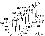
图9是根据本发明的优选实施例的相应于图5的子信道比特的频率域表示。FIG. 9 is a frequency domain representation of subchannel bits corresponding to FIG. 5 according to a preferred embodiment of the present invention.
图10是根据本发明优选实施例说明通过产生一个窗口对子信道中的比特解码的频率域表示。Figure 10 is a frequency domain representation illustrating decoding of bits in a subchannel by generating a window in accordance with a preferred embodiment of the present invention.
图11是根据本发明的优选实施例的选呼接收机操作的流程图。Fig. 11 is a flowchart of the operation of the selective call receiver according to the preferred embodiment of the present invention.
参见图1,该图表示根据本发明的优选实施例的选呼通信系统100。选呼通信系统100包括一个终端/控制器104,经调制解调器(Modem)101连接到一个计算机(未示出),和经常规的公用或专用电话网102连接到传真(FAX)机103和电话机116,这对于本领域的普通技术人员是熟知的。电话网102通过终端/控制器104连接到多个选呼基站(或站址)120-124。多个选呼基站120-124经其相应的发射机/接收机110-114发送和接收信号,下文将讨论选呼基站110-114操作的详细情况。多个选呼基站120-124具有相关的覆盖区(例如105和106),来自终端/控制器104的信号广播到这些区并由多个选呼接收机的至少一个选呼接收机108接收。Referring to FIG. 1, there is shown a selective call communication system 100 in accordance with a preferred embodiment of the present invention. Selective call communication system 100 comprises a terminal/controller 104, is connected to a computer (not shown) through modem (Modem) 101, and is connected to facsimile (FAX) machine 103 and telephone set through conventional public or private telephone network 102 116, which is well known to those of ordinary skill in the art. Telephone network 102 is connected through terminal/controller 104 to a plurality of selective call base stations (or sites) 120-124. A plurality of selective call base stations 120-124 transmit and receive signals via their respective transmitter/receivers 110-114, details of the operation of selective call base stations 110-114 are discussed below. A plurality of selective call base stations 120-124 have associated coverage areas (eg, 105 and 106) to which signals from terminal/controller 104 are broadcast and received by at least one selective call receiver 108 of the plurality of selective call receivers.
参见图2,该图示出根据本发明的优选实施例的选呼基站120-124的详细的方框图。选呼基站120-124含有一个电话互连装置201,该互连装置允许消息通过公用或专用电话网络例如使用电话机116、计算机102、传真机103或字母数字输入设备(未示出)输入到选呼通信系统100。通信终端202例如摩托罗拉公司的MODEN PLUS编码器,处理通过电话互连装置201接收的信息。产生的地址和从接收的信息解码的消息被存储在存储器204中,直到下一个传输周期。Referring to FIG. 2, there is shown a detailed block diagram of selective call base stations 120-124 in accordance with a preferred embodiment of the present invention. Selective call base stations 120-124 contain a telephone interconnection means 201 which allows messages to be entered over a public or private telephone network, e.g. Selective call communication system 100 . The
如图所示,通信终端202连接到一个控制器206,该控制器控制链路发射机208、通信发射机210、链路接收机212和通信接收机214的操作。适合于在本发明中使用的控制器例如是摩托罗拉公司的MC6809控制器。连接到控制器206的定时发生器216提供高精度的时钟,以维持通信的系统定时,和以本领域技术人员熟知的技术使包括所有选呼基站120-124和多个选呼接收机108的选呼通信系统100的同步。在操作上,该通信发射机210向多个选呼接收机108发送信号,该信号在第一频率上在该传输周期最好地包括寻呼类型消息。最好地,由通信发射机210指定(寻址)一组选呼接收机接收寻呼消息。众所周知,在发送传输之前该寻呼消息用合适的地址编码,用于寻址多个选呼接收机108的选呼接收机组。例如,和根据本发明的优选实施例,当多个选呼接收机108组已有寻呼机时,接收消息的那组选呼接收机将基本上同时地发送响应,返回确认信号。最好地,该返回确认响应(确认)最好在基本上低于第一频率的第二频率上发送。选呼基站120-124的接收机214接收返回确认响应(确认信号或返回确认信号),该信号存储在存储器204中。如所周知的,接收机214解调返回确认信号,最好产生基带信号。该基带信号由模/数(A/D)变换器220从模拟信号变换(数字化)到数字信号,这是本领域的技术人中熟知的。由A/D变换器220的变换是由数字信号处理器(DSP)218接收并存储。例如DSP218可包括摩托罗拉公司的DSP56100或TexasInstrument公司的TMS3000系列数字信号处理器。根据本发明的优选实施例,DSP218存储数字化的样值作为数字化的比特并连续地接收和存储数字化样值,直到返回确认信号的所有比特已被接收和存储为止。数字化的样值被检索而且每个比特被变换为其频率域表示。最好地,DSP218对每个数字化比特执行快速付里叶变换(FFT),以产生频率域信号,该信号包括接收的多个返回确认信号,作为来自选呼接收机108组的响应选呼接收机的复合时间域信号。定时发生器216连接到DSP218,以提供用于处理包括每个返回确认信号的多个数字化比特的同步和定时。下文将详细描述DSP218的操作。As shown,
参见图3,该图示出根据本发明的优选实施例的选呼接收接收机的电气方框图。选呼接收机108包括一个天线302,用于接收发送的射频(RF)信号,这些信号被耦合到接收机304的输入端。RF信号最好是选呼(寻呼)消息信号,例如该信号提供接收机地址和相关消息例如数字的或字母数字的。但是,应当知道其它熟知的寻呼信令格式,例如仅是单音信令或单音和话音信令将是适用的。接收机304处理RF信号并在输出端产生代表解调数据信息的数据流。解调的数据信息耦合到解码器/控制器306的输入端,该解码器/控制器306以现有技术中熟知的方式处理该信息。发射机334耦合到天线302和解码器/控制器306。连接到解码器/控制器306的电源开关310用于控制接收机304的电源,因此提供节电的功能,还控制发射机334的电源,以在接收寻呼消息之后发送返回确认响应,下文将详细描述。Referring to FIG. 3, there is shown an electrical block diagram of a selective call receiver according to a preferred embodiment of the present invention. Selective call receiver 108 includes an antenna 302 for receiving transmitted radio frequency (RF) signals which are coupled to an input 304 of the receiver. The RF signal is preferably a selective call (paging) message signal, eg, which provides a receiver address and associated information, eg numeric or alphanumeric. However, it should be appreciated that other well-known paging signaling formats, such as tone-only signaling or tone and voice signaling, would be suitable. Receiver 304 processes the RF signal and produces at an output a data stream representing demodulated data information. The demodulated data information is coupled to an input of decoder/
为了便于说明起见,假定使用POCSAG信令格式,这种格式在现有技术中已熟知了,也可使用其它信令格式。当由解码器/控制器306接收该地址时,接收的地址与在码插件(或码存储器)322中存储的一个或多个地址进行比较,并且当检测到它们相符时,产生一个提醒信号,提醒用户已接收到选呼消息或寻呼。提醒信号传送到可闻提醒装置314,用于产生可闻的提醒,或到触觉提醒装置316,用于产生无声的振动提醒。开关320允许选呼接收机的用户以现有技术中熟知的方式在可闻的提醒314和触觉提醒316之间选择。For ease of illustration, it is assumed that the POCSAG signaling format is used, which is well known in the art, but other signaling formats may also be used. When the address is received by the decoder/
随后接收的消息信息被存储在存储器404(图4)中,并且使用一个或多个开关320可由用户存取用于显示,并提供这样的附加功能,如复位、读取和删除等。具体地说,通过使用由开关320提供的适当功能,存储的消息从存储器中恢复并由解码器/控制器306处理,由显示器308显示,使用户能观看到该消息。由选呼接收机108接收的消息能自动地产生返回确认响应至选呼基站,通知该基站该消息已成功地接收。最好地是,用户有机会通过使用开关320或在本领域中普通技术人员熟知的一些其它输入装置输入一个消息。当输入该消息时,编码器/控制器306通过编码来自接收消息的地址处理该消息,以产生返回确认响应。然后发送该编码的返回确认响应到通过本领域中普通技术人员熟知的技术始发寻呼消息的选呼基站。Subsequent received message information is stored in memory 404 (FIG. 4) and is accessible by the user for display using one or more switches 320, and provides such additional functions as reset, read, and delete, among others. Specifically, by using the appropriate function provided by switch 320, the stored message is retrieved from memory and processed by decoder/
图3的解码器/控制器306可利用一个微计算机来实施,如图4所示,图4示出适合于图3的选呼接收机中使用的解码器/控制器型微计算机的电气方框图。图中,微计算机306最好是例如由摩托罗拉公司生产的MC68HC05系列微计算机,该微计算机包括在板显示驱动器414。微计算机306包括一个振荡器418,它产生定时信号,用于微计算机的操作中。一个晶体或晶体振荡器(未示出)连接到振荡器418的输入端,为建立微计算机的定时提供基准信号。定时器/计数器402连接到振荡器418并提供可编程的定时功能,这些功能被用在接收机或处理器的控制操作中。RAM(随机存取存储器)404被用于存储在处理期间得到的变量,并且提供消息信息的存储,这些信息是在选呼接收机的工作期间接收的。ROM(只读存储器)406存储控制接收机或处理器操作的子程序,这些将进一步讨论。可以理解,在许多微计算机的实施中,可编程的ROM(PROM)存储区可由可编程的只读存储器(PROM)或EEPROM(电子的可擦除可编程只读存储器)来提供。振荡器418、定时器/计数器402、RAM404、和ROM 406通过地址/数据/控制总线408连接到中央处理单元(CPU),该单元执行命令和控制微计算机306的操作。The decoder/
由接收机产生的解调的数据通过输入/输出(I/O)端口412耦合到微计算机306。解调的数据由CPU410处理,并且当接收的地址与在码插件存储器内存储的地址相同时,如果接收到任何消息并存储在RAM404中,其中码插件存储器例如通过I/O端口413耦合到微计算机。通过连接到I/O端口412的开关提供存储消息的恢复和预定目的地地址的选择。然后,微计算机306恢复存储的消息并径数据总线408传送该信息到显示驱动器414,该显示驱动器414处理该信息并格式化该信息,通过显示器308(图3)例如LCD(液晶显示器)来再现。在接收选呼接收机的地址时,产生提醒信号,该信号通过数据总线408传送到提醒发生器416,该发生器416产生提醒启动信号,该信号耦合到上面描述的可闻提醒器件。另一种方案,当选择振动器提醒时,如上所述,该微计算机产生一个提醒启动信号,该信号通过数据总线408耦合到I/O端口413使产生振动或无声的提醒。由I/O端口412经数据总线408接收开关的输入。开关的输入由CPU410处理。具体地说,CPU410从RAM404检索选呼基站的地址并结合定时器计数器402和振荡器418,CPU410产生返回确认信号,该信号经数据总线408传送到发射机。The demodulated data produced by the receiver is coupled to
CPU410用节电信号控制节电器的工作,该节电信号经数据总线408传送到I/O端口412,该端口412耦合到电源开关310。电源被周期地提供到接收机,以便使传送到选呼接收机的接收的选呼接收机地址信号和任何消息信息能解码。具体地说,当选呼接收机108开始解码寻呼信号时,由电源开关对接收机供电。当该寻呼消息被接收和被存储时,微计算机306发送一个信号到电源开关310,使之不对接收机304供电只对发射机供电,以便发送返回确认信号。The
参见图5,该图是表示根据本发明的优选施例的一个选呼接收机组的返回确认(ack-back)信号的比特图型例子的定时图。正如所讨论的,返回确认信号是在比来自选呼基站的寻呼信号低的频率。例如,寻呼信号是在16至30Kbs(千比特/秒)的范围内,而返回确认信号例如是在100比特/秒的范围内。比特图型500表示对于一个子信道被寻呼的选呼接收机组的一个选呼接收机的一个返回确认信号的例子。比特图型表示比特502、506、510和516-518代表数字的“1”,而比特504、508和512-514代表数字的“0”。确认返回响应最好地包括具有300比特的比特图型,比特的值取决于被传送的信息。例如,N个数目的选呼接收机108组,在组数之后通过发送N或更少的返回确认响应,选呼基站将接收复合的比特,该复合的比特包括在每个比特时间包含N个或更少的返回确认响应,这些将在下文详细讨论。Referring to FIG. 5, this figure is a timing diagram showing an example of a bit pattern of an ack-back signal of a selective call receiver group according to a preferred embodiment of the present invention. As discussed, the return acknowledgment signal is at a lower frequency than the paging signal from the selective call base station. For example, paging signals are in the range of 16 to 30 Kbs (kilobits per second), while return acknowledgment signals are for example in the range of 100 bits per second. Bit pattern 500 shows an example of a return acknowledgment signal for a selective call receiver of a subchannel paged selective call receiver group. The bit pattern shows that
参见图6,该图示出30KHz信道的频率域表示,例如10个子信道(10个确认返回响应)根据本发明的优选实施例,它们代表返回确认信号的频率域表示。如上所述,因由选呼基站接收的每个比特包含复合比特,故变换复合比特为其频率表示可产生表示在它们的子信道中的N例如10个返回确认信号的频率域信号。优选的调制方案是用10个选呼接收机108的多个选呼接收机的二进制频移键控(FSK),该接收机在指配给优选的10个子信道1-10之一的组内。例如,该组的10个选呼接收机108的每一个接收机被指配给相应于10个子信道之中的一个不同子信道。子信道1-10在代表“1”602的单音和代表“0”612的单音之间大约分离开300Hz。每一个子信道1-10被安置在中心轴650上,它标志每个信道1-10的中心,用于解码每个子信道的“1”或“0”单音。本领域的技术人员所知道,选呼接收机的振荡器必须以足够地精确,以防止在其子信道指配内的信号偏移到指配给该组的其它选呼接收机的相邻子信道的任何一个子信道。Referring to FIG. 6, this figure shows a frequency domain representation of a 30KHz channel, for example, 10 sub-channels (10 acknowledgment return responses) according to a preferred embodiment of the present invention, which represent frequency domain representations of return acknowledgment signals. As described above, since each bit received by the selective call base station contains a composite bit, converting the composite bits to their frequency representation produces a frequency domain signal representing N, eg, 10 return acknowledgment signals in their subchannels. The preferred modulation scheme is binary frequency shift keying (FSK) with multiple selective call receivers of ten selective call receivers 108 within the group assigned to one of the preferred ten subchannels 1-10. For example, each receiver of the set of ten selective call receivers 108 is assigned to a different subchannel corresponding to one of the ten subchannels. Subchannels 1-10 have approximately 300 Hz separation between the tone representing a "1" 602 and the tone representing a "0" 612 . Each subchannel 1-10 is positioned on a
参见图7,该图示出根据本发明的优选实施例的选呼基站的DSP解码操作的流程图。在操作时,选呼基站120-124(图2)接收和编码例如预定给选呼接收机的预指配组,最好是10个为一组所希望的消息。在步骤702,编码的寻码消息被发送到选呼接收机组。在步骤704,在传输之后,选呼基站120-124来自选呼接收机组的返回确认响应。在步骤706,检测何时从选呼接收机组接收基本上同时地到达返回确认信号。众所周知,每个选呼接收机可能放置在选呼基站的覆盖区内的任何地方,因此,例如不管其位置如何,多一个选呼接收机在发送其返回确认信号之前将延迟,以保证该组的所有选呼接收机将以基本上相同的时间发送。多个选呼接收机根据接收的寻呼信号计算它的延迟,例如,该寻呼信号可能包含指示传输时间的信息,该信息用于确定发送返回确认信号的延迟时间。Referring to FIG. 7, this figure shows a flowchart of the DSP decoding operation of the selective call base station according to the preferred embodiment of the present invention. In operation, the selective call base stations 120-124 (FIG. 2) receive and encode, for example, pre-assigned groups, preferably groups of ten, of desired messages intended for selective call receivers. At step 702, the coded code hunting message is sent to the group of selective call receivers. At step 704, after the transmission, the selective call base station 120-124 returns an acknowledgment response from the group of selective call receivers. In step 706, it is detected when substantially simultaneously arriving return acknowledgment signals are received from the group of selective call receivers. As is well known, each selective call receiver may be placed anywhere within the coverage area of a selective call base station, so, for example, regardless of its location, an additional selective call receiver will delay before sending its return acknowledgment signal to ensure that the group All selective call receivers of will transmit at substantially the same time. A plurality of selective call receivers calculates its delay from the received paging signal, which may, for example, contain information indicating the time of transmission which is used to determine the delay time for sending a return acknowledgment signal.
在步骤708,当接收到返回确认信号时,因A/D变换器包括一个取样和保持电路(S/H),故该电路最好地以60HKz速率取样这些比特(因在返回确认信号中出现的最高频率是30KHz)。对于每个比特,因返回确认信号的频率是100Hz而取样频率是60KHz,故这里有600个样值。在步骤710,根据所表示的比特这些样值被数字化,组织和存储。步骤708和710被重复,直到收到返回确认信号的所有比特,例如300比特。代表每个比特的数字化样值被辨别并从存储器中检索。在步骤712,600个样值最好地用424个“0”增加(填充),产生1024个样值,它是快速付里叶变换(FFT)要求的2的乘方。在步骤714,DSP将返回确认信号的时间表示变换为频率表示(频率域信号),这是通过对返回确认信号的每个比特执行FFT实现的。在步骤716,存储这些频率样值,然后组织成矩阵格式用于后续处理。In step 708, when the acknowledgment is received, since the A/D converter includes a sample and hold circuit (S/H), the circuit preferably samples these bits at a rate of 60 HKz (due to the occurrence of the acknowledgment in the acknowledgment The highest frequency is 30KHz). For each bit, since the frequency of returning the confirmation signal is 100Hz and the sampling frequency is 60KHz, there are 600 samples here. At step 710, the samples are digitized, organized and stored according to the represented bits. Steps 708 and 710 are repeated until all bits of the return acknowledgment signal are received, for example 300 bits. Digitized samples representing each bit are identified and retrieved from memory. In step 712, the 600 samples are preferably augmented (filled) with 424 "0's", resulting in 1024 samples, which is the power of 2 required by the Fast Fourier Transform (FFT). In step 714, the DSP transforms the time representation of the returned acknowledgment signal into a frequency representation (frequency domain signal) by performing an FFT on each bit of the returned acknowledgment signal. At step 716, these frequency samples are stored and then organized into a matrix format for subsequent processing.
参见图8,说明根据本发明的优选实施例具有相应于比特数的行和相应于频率样值数的列的矩阵表示。矩阵1-10相应于图6中表示的子信道1-10。矩阵1的行被编号为1-300,相应于返回确信信号的300比特。矩阵1的列编号为1-51,代表每个子信道的频率样值数。正如前面所讨论的,每个比特包括1024个频率样值(在填充之后),和因为出现的最高频率分量是30KHz,那么514个高次频率样值可被丢弃,而不影响频谱信号表示的完整性。10个子信道1-10保持510个频率样值。因此每个子信道用51个样值代表,并通过处理每个矩阵,每个子信道可与其它子信道无关的处理,因为它的唯一矩阵表示。Referring to FIG. 8, there is illustrated a matrix representation having rows corresponding to the number of bits and columns corresponding to the number of frequency samples in accordance with a preferred embodiment of the present invention. Matrices 1-10 correspond to subchannels 1-10 shown in FIG. 6 . The rows of matrix 1 are numbered 1-300, corresponding to the 300 bits of the return acknowledgment signal. The columns of matrix 1 are numbered 1-51, representing the number of frequency samples for each subchannel. As discussed earlier, each bit consists of 1024 frequency samples (after padding), and since the highest frequency component present is 30KHz, the 514 higher order frequency samples can be discarded without affecting the spectral signal representation integrity. The 10 sub-channels 1-10
再参见图7,在步骤718,在多个频率(子信道)的每一个频率产生一个窗口,用于解码返回确认响应信息。在步骤720,该窗口被定位,用于在整个子信道1的300比特上定位子信道1的频率域信号的峰值。最好地,该窗口是足够宽,能测量51个样值线的8个样值线。一旦窗口被定位,在步骤722,最好地在300比特的最低8个样值上,累加8个样值线。累加的8个样值线代表窗口的总能量。在步骤724,然后窗口被移位到下一个位置,最好移动一个样值线高。在步骤726,通过相加(累加)初始的7个样值线加上附加的一个样值线再次测量能量,得到另一个能量值作为新的窗口位置。Referring to FIG. 7 again, in step 718, a window is generated in each of the plurality of frequencies (sub-channels) for decoding the returned acknowledgment response information. In step 720, the window is positioned for locating the peak of the frequency domain signal of subchannel 1 over the entire 300 bits of subchannel 1. Preferably, the window is wide enough to measure 8 of the 51 sample lines. Once the window is positioned, at step 722, 8 sample lines are accumulated, preferably over the lowest 8 samples of 300 bits. The accumulated 8 samples represent the total energy of the window. At step 724, the window is then shifted to the next position, preferably one sample line high. In step 726, the energy is measured again by adding (accumulating) the original 7 samples plus an additional one sample to obtain another energy value as a new window position.
参见图9,根据本发明的优选实施例表示相应于图5的子信道比特的频率域表示。时间域比特图(图5)的频率域信号表示在子信道1的频谱变换之后多个比特如何出现。比特502、506、510和516表示“1”,由指示窗口902的第一半的线904辨别。比特504、508和512-514表示“0”,由指示窗口902的第二半的线906辨别,正如所讨论的,该返回确认信号是数字FSK调制,这里二进制“1”被指定为较低频率单音602(见图6)和二进制“0”被指定为较高频率单音612(见图6)。窗口902被表示定位在多个子信道的所有比特上,这里比特502-516相应于第一个8比特,和该窗口在下一个292比特上继续以包围多个返回确认信号(子信道)的300比特。Referring to FIG. 9, a frequency domain representation corresponding to the subchannel bits of FIG. 5 is shown in accordance with a preferred embodiment of the present invention. The frequency domain signal of the time domain bitmap (FIG. 5) shows how multiple bits appear after the spectral transformation of subchannel 1.
按照这种方式,移动窗口的位置,直到定位最大能量为止。即相应于在子信道1的所有300比特上的频率域信号的峰值。In this way, the position of the window is moved until the maximum energy is located. That is, corresponds to the peak value of the frequency domain signal over all 300 bits of subchannel 1.
参见图10,该图示出根据本发明优选实施例通过产生该窗口来子解码子信道比特的频率域表示。用虚线表示相应于二进制“0”的单音612,而实线表示相应于二进制“1”的单音602。窗口902被理想地定位,表示在偏离于子信道1的中心650出现的单音。“0”单音的虚线表示说明如果该比特是“0”而不是“1”,零单音出现的位置。应当懂得“1”和“0”互相排它出现。Referring to FIG. 10, this figure shows a frequency-domain representation of sub-decoded sub-channel bits by generating the window according to a preferred embodiment of the present invention. The
再参见图7,在步骤728,在测量第二窗口位置的能量之后,相互比较能量的值,以确定相应于最大能量的窗口位置。在步骤730,检查是否测量了所有窗口位置。如果“否”,则DSP进程继续到步骤724,用于移动到另一个窗口位置。在步骤730,当测量了所有窗口位置时,进程继续到步骤732,划分窗口902为两半,在步骤734,检查窗口902的能量,确定总的能量是否超过阈值。在步骤736,阈值指示何时在子信道上出现一个信号,因此如果能量值低于阈值,对于那个子信道该进程停止。否则,进程继续进行到步骤738,比较第一半窗口902的能量和第二半窗口902的能量。在步骤740,果第一半窗口902的能量大于第二半窗口902的能量,则在步骤744该比特被解码为二进制“1”,否则在步骤742,该比特被解码为二进制“0”。Referring again to FIG. 7, in step 728, after measuring the energy at the second window position, the energy values are compared with each other to determine the window position corresponding to the maximum energy. At step 730, it is checked whether all window positions have been measured. If "NO", the DSP process continues to step 724 for moving to another window position. At step 730, when all window positions have been measured, the process continues to step 732 where
按照这种方式,本发明解码代表来自多个选呼机响应的多个子信道。每个选呼接收机在预先指配的子信道上响应,虽然最好地存在着能基本上同时响应的最多10个选呼接收机,但本发明不要求10个单独的带通滤波器接收每个子信道上的多个返回确认信号。在每个子信道的滤滤器将不提供用于解码多个返回确认信号的成本有效的解决办法。而且,由于滤波器的响应不可能比总的子信道少,以保证接收返回确认信号,所以信号噪声比(SNR)将降低至少51比8的比值,因为该窗口能够检测在8个样值分辨率之内的返回确认信号的峰值,而同时滤波器的响应将至少具有51个样值这样宽,以保证信号不丢失。In this manner, the present invention decodes multiple subchannels representing responses from multiple selective callers. Each selective call receiver responds on a pre-assigned sub-channel, although there are preferably at most 10 selective call receivers that can respond substantially simultaneously, the present invention does not require 10 separate bandpass filter reception Multiple return acknowledgments on each subchannel. A filter on each subchannel would not provide a cost effective solution for decoding multiple return acknowledgment signals. Also, since the response of the filter cannot possibly be less than the total subchannels to guarantee reception of the return acknowledgment signal, the signal-to-noise ratio (SNR) will be reduced by at least a factor of 51 to 8, since the window is able to detect The peak of the return confirmation signal within the rate, while the response of the filter will be at least 51 samples wide to ensure that the signal is not lost.
即使每个子信道的带通滤波器响应被降低到子信道的大小之下,以改进SNR,这种降低将使得该滤波器不能检测那些落到滤波器响应之外,但仍在分配的子信道之内的返回确认比特。因此,通过FFT复合比特并解码频率域中的多个返回确认信号,本发明不需要多个滤波器,因此提供了一种从多个选呼接收机中检测多个返回确认信号的成本有效的方法,而同时保持接收信号的SNR最大。Even if the bandpass filter response for each subchannel is reduced below the size of the subchannel to improve SNR, this reduction will prevent the filter from detecting those subchannels that fall outside the filter response but are still allocated within the returned acknowledgment bits. Thus, by FFT-compositing the bits and decoding the multiple acknowledgment signals back in the frequency domain, the present invention does not require multiple filters and thus provides a cost effective method of detecting multiple acknowledgment signals back from multiple selective call receivers. method, while maintaining the maximum SNR of the received signal.
图11示出根据本发明的优选实施例的选呼接收机操作的流程图。在步骤1102,选呼接收机108从选呼基站接收寻呼信号,和在步骤1104解码其地址和包含在其中的消息(如果有的话)。在步骤1104,寻呼信号最好地包括也被解码的传输时间在它通过发送返回确认响应之前,使选呼接收机108能够计算延迟时间。在步骤1106,选呼基站的地址也从接收的寻呼信号中被解码。在步骤1108,选呼接收机108延迟直到一个消息被输入或者直到发送返回确认响应的时间为止。最好地,在步骤1110,选呼接收机108提供一个任选,使用户能通过本领域熟知的技术输入合并在返回确认响应内的消息。如果该消息设有被输入或发送时间没有过去,进程继续到步骤1108。另一种情况,如要输入了一个消息,在步骤1112,该消息用基站的地址编码,或者如果时间已过去,返回确认信号用违约(default)消息编码。在一些情况下,选呼接收机可能不需要从发送的选呼基站接收地址并且在其预指配的子信道上简单地发送其消息至选呼基站。在步骤1114,当接收和编码返回确认消息时,选呼接收机延迟,直到其发送返回确认响应时为止。在步骤1116,返回确认响应被发送到选呼基站。Fig. 11 is a flowchart showing the operation of the selective call receiver according to the preferred embodiment of the present invention. In step 1102, selective call receiver 108 receives a paging signal from a selective call base station, and in step 1104 decodes its address and the message (if any) contained therein. In step 1104, the paging signal preferably includes a transmission time that is also decoded before it is returned by sending an acknowledgment response, enabling the selective call receiver 108 to calculate the delay time. In step 1106, the address of the selective call base station is also decoded from the received paging signal. In step 1108, the selective call receiver 108 delays until a message is entered or until it is time to send back an acknowledgment response. Preferably, at step 1110, selective call receiver 108 provides an option for the user to enter a message incorporated within the return confirmation response by techniques well known in the art. If the message has not been entered or the sending time has not elapsed, the process continues to step 1108. Alternatively, if a message is to be entered, at step 1112, the message is encoded with the address of the base station, or if time has elapsed, the return acknowledgment is encoded with a default message. In some cases, a selective call receiver may not need to receive an address from the sending selective call base station and simply send its message to the selective call base station on its pre-assigned sub-channel. In step 1114, upon receiving and encoding the return acknowledgment message, the selective call receiver delays until it sends the return acknowledgment response. At step 1116, a return acknowledgment response is sent to the selective call base station.
按照这种方式,在一组中的多个选呼接收机通过解码寻呼信号的传输时间知道在覆盖区的外缘内的任何选呼接收机的接收寻呼和发送返回确认消息的最长时间。选呼接收机能够延迟指示其当前位置的适当时间,保证多个选呼接收机基本上同时地响应。In this manner, multiple selective call receivers in a group know the longest time period for receiving a page and sending a return acknowledgment message for any selective call receiver within the outer edge of the coverage area by decoding the transmission time of the paging signal. time. A selective call receiver can delay indication of its current location by an appropriate time, ensuring that multiple selective call receivers respond substantially simultaneously.
总之,选呼基站接收包括多个通信信号的信号。选呼基站包括一个模/数(A/D)变换器,用于数字化该信号为多个数字化比特。A/D变换器进一步包括一个取样和保持(S/H)电路,用于以预定的取样速率取样该信号,为多个数字化比特的每一比特产生多个数字化样值。一个存储器,存储相应于多个数字化样值的信号,和一个数字信号处理器(DSP)变换多个数字化比特的每一比特为频率域信号,该信号包括多个频率样值。DSP进一步包括一个识别器,以识别相应于多个数字化比特的每一比特的多个数字化样值。一个填充电路将多个数字化比特的多个数字化样值增加到2的乘方。DSP对相应于多个数字化比特的每一比特的多个数字化样值执行快速付里叶变换(FFT),以产生多个频率样值。一个表组织器以矩阵形式组织多个频率样值,该矩阵具有包括多个数字比特的多个行和包括多个频率样值的多个列。该存储器存储相应于多个数字化比特的多个比特的多个频率样值,和一个解码器从多个频率样值中解码多个通信信号。该解码器进一步包括,产生一个窗口的一个产生器用于测量多个通信信号的每一个信号中多个数字化比特的至少一个频率样值的能量。该产生器进一步包括一个控制器,用于在相应于频率域信号的多个数字化比特之一上定位窗口。一个累加器累加该窗口内的至少一个频率样值,用于测量该窗口的能量。该控制器移动该窗口,用于测量多个频率样值的另一个样值。控制器继续移动该窗口,直到测量完多个通给信号之一的多个频率样值。一个确定器确定多个通信信号的每一个信号的至少一个频率样值,它具有最大的能量。该确定器进一步包括比较窗口的多个位置的能量的一个比较器用于确定相应于最大能量的窗口的位置。一个划分器,划分相应于最大能量的窗口为第一和第二部分,和比较器比较第一位置和第二位置,确定多个数字化比特的二进制表示。In summary, a selective call base station receives a signal including a plurality of communication signals. The selective call base station includes an analog-to-digital (A/D) converter for digitizing the signal into a plurality of digitized bits. The A/D converter further includes a sample and hold (S/H) circuit for sampling the signal at a predetermined sampling rate to produce a plurality of digitized samples for each of the plurality of digitized bits. A memory stores a signal corresponding to the plurality of digitized samples, and a digital signal processor (DSP) converts each of the plurality of digitized bits into a frequency domain signal comprising the plurality of frequency samples. The DSP further includes an identifier for identifying a plurality of digitized samples corresponding to each bit of the plurality of digitized bits. A stuffing circuit increases the digitized samples of the digitized bits to a power of two. The DSP performs a Fast Fourier Transform (FFT) on a plurality of digitized samples corresponding to each of the plurality of digitized bits to generate a plurality of frequency samples. A table organizer organizes frequency samples in a matrix having rows including digital bits and columns including frequency samples. The memory stores a plurality of frequency samples for a plurality of bits corresponding to the plurality of digitized bits, and a decoder decodes a plurality of communication signals from the plurality of frequency samples. The decoder further includes a generator generating a window for measuring the energy of at least one frequency sample of the plurality of digitized bits in each of the plurality of communication signals. The generator further includes a controller for positioning a window on one of the plurality of digitized bits corresponding to the frequency domain signal. An accumulator accumulates at least one frequency sample within the window for measuring the energy of the window. The controller moves the window for measuring another one of the plurality of frequency samples. The controller continues to move the window until a plurality of frequency samples of one of the plurality of passing signals has been measured. A determiner determines at least one frequency sample of each of the plurality of communication signals which has the greatest energy. The determiner further includes a comparator for comparing the energies of positions of the window for determining the position of the window corresponding to the maximum energy. A divider divides the window corresponding to the maximum energy into first and second portions, and a comparator compares the first position with the second position to determine a binary representation of the plurality of digitized bits.
按照这种方式,本发明解码代表来自多个选呼接收机响应的多个子信道。多个选呼接收机在预指配的子信道上响应。虽然最好地存在着能基本上同时响应的最多10个选呼接收机,但本发明要要求10个单独的带通滤波器接收每个子信道上的多个返回确认信号。在多个子信道上的滤波器将不提供用于解码多个返回确认信号的成本有效的解决办法。而且,由于滤波器的响应不可能比总的子信道少,以保证接收返回确认信号,信噪比(SNR)将降低至少51比8的比值,因为该窗口能够检测在8个样值分辨率之内的返回确认信号的峰值,而滤波器的响应将至少具有51个样值这样宽,以保证信号不被丢失。In this manner, the present invention decodes multiple subchannels representing responses from multiple selective call receivers. Multiple selective call receivers respond on preassigned subchannels. Although there are preferably at most ten selective call receivers that can respond substantially simultaneously, the present invention requires ten separate bandpass filters to receive multiple return acknowledgment signals on each subchannel. Filters on multiple subchannels will not provide a cost effective solution for decoding multiple return acknowledgment signals. Also, since the filter response is unlikely to be less than the total sub-channel to ensure reception of the return acknowledgment signal, the signal-to-noise ratio (SNR) will be degraded by at least a 51 to 8 ratio, since the window is able to detect The peak of the confirmation signal is returned within , and the filter response will be at least 51 samples wide to ensure that the signal is not lost.
即使每个子信道的带通滤波器响应被降低到低于子信道的大小来以改进SNR,这种降低将使得该波器不能检测那些落到滤波器响应之外但仍在分配的子信道之内的返回确认比特。因此,本发明提供了一种从多个选呼接收机中检测多个返回确认信号的经济实惠的方法,而同时保持接收信号的SNR最大。Even if the bandpass filter response for each subchannel is reduced below the size of the subchannel to improve SNR, this reduction will prevent the filter from detecting those subchannels that fall outside the filter response but are still within the assigned subchannel. Return acknowledgment bits within. Accordingly, the present invention provides an economical method of detecting multiple return acknowledgment signals from multiple selective call receivers while maximizing the SNR of the received signal.
Claims (25)
Applications Claiming Priority (2)
| Application Number | Priority Date | Filing Date | Title |
|---|---|---|---|
| US08/112,156 US5450612A (en) | 1993-08-26 | 1993-08-26 | Communication system for communicating with a plurality of selective call receivers and method therefor |
| US08/112,156 | 1993-08-26 |
Publications (1)
| Publication Number | Publication Date |
|---|---|
| CN1136871A true CN1136871A (en) | 1996-11-27 |
Family
ID=22342379
Family Applications (1)
| Application Number | Title | Priority Date | Filing Date |
|---|---|---|---|
| CN94193156A Pending CN1136871A (en) | 1993-08-26 | 1994-08-18 | Communication system for communicating with a plurality of selective call receivers and method thereof |
Country Status (12)
| Country | Link |
|---|---|
| US (1) | US5450612A (en) |
| EP (1) | EP0716789A4 (en) |
| JP (1) | JP2718266B2 (en) |
| KR (1) | KR100193972B1 (en) |
| CN (1) | CN1136871A (en) |
| AU (1) | AU675578B2 (en) |
| BR (1) | BR9407467A (en) |
| CA (1) | CA2166304A1 (en) |
| CZ (1) | CZ286143B6 (en) |
| PL (1) | PL175115B1 (en) |
| TW (1) | TW252251B (en) |
| WO (1) | WO1995006364A1 (en) |
Families Citing this family (19)
| Publication number | Priority date | Publication date | Assignee | Title |
|---|---|---|---|---|
| US5708971A (en) * | 1994-01-11 | 1998-01-13 | Ericsson Inc. | Two-way paging system and apparatus |
| US5550872A (en) * | 1994-10-24 | 1996-08-27 | Motorola, Inc. | Method and apparatus for Fast Fourier Transform based maximal ratio combining |
| GB9423328D0 (en) * | 1994-11-18 | 1995-01-11 | Philips Electronics Uk Ltd | Improvements in or relating to spread spectrum signalling schemes |
| US5722048A (en) * | 1994-12-02 | 1998-02-24 | Ncr Corporation | Apparatus for improving the signal to noise ratio in wireless communication systems through message pooling and method of using the same |
| US5627528A (en) * | 1995-02-28 | 1997-05-06 | Motorola, Inc. | Selective call receiver capable of suspending acknowledge-back signals and method therefor |
| US5832038A (en) * | 1996-07-03 | 1998-11-03 | Motorola, Inc. | Method and apparatus for classifying a multi-level signal |
| US6055414A (en) * | 1996-07-23 | 2000-04-25 | Ncr Corporation | System and method for improving reliability and performance of wireless communication systems using message pooling |
| US5909433A (en) * | 1996-08-30 | 1999-06-01 | Telefonaktiebolaget L M Ericsson (Publ) | Method and apparatus for acquiring low duty-cycle reference signals in a mobile communications environment |
| US5832026A (en) * | 1996-12-04 | 1998-11-03 | Motorola, Inc. | Method for correcting errors from a fading signal in a frequency hopped spread spectrum communcation system |
| US5793795A (en) * | 1996-12-04 | 1998-08-11 | Motorola, Inc. | Method for correcting errors from a jamming signal in a frequency hopped spread spectrum communication system |
| TW381376B (en) * | 1997-11-14 | 2000-02-01 | Eten Information System Co Ltd | Communication device for multi-channel radio frequency module |
| KR100249045B1 (en) * | 1997-12-29 | 2000-03-15 | 김영환 | How to adjust search window size of base station |
| KR100293996B1 (en) * | 1998-08-06 | 2001-07-12 | 윤종용 | Advanced transfering method of short message in digital portable telephone |
| DE19942944A1 (en) * | 1999-09-08 | 2001-03-22 | Infineon Technologies Ag | Communication system and corresponding recipient |
| US7957263B2 (en) * | 2003-09-08 | 2011-06-07 | Qualcomm Corporation | Method and apparatus for acknowledging reverse link transmissions in a communications system |
| WO2006112831A1 (en) * | 2005-04-15 | 2006-10-26 | Mitsubishi Electric Research Laboratories | Method and system for estimating time of arrival of signals using multiple different time scales |
| US8893210B2 (en) * | 2010-08-20 | 2014-11-18 | Sony Corporation | Server load balancing for interactive television |
| US8918801B2 (en) | 2010-08-30 | 2014-12-23 | Sony Corporation | Transmission apparatus, transmission method, reception apparatus, reception method, program, and broadcasting system |
| CN110035355B (en) * | 2018-01-12 | 2022-06-07 | 北京京东尚科信息技术有限公司 | Method, system, equipment and storage medium for microphone array to output sound source |
Family Cites Families (10)
| Publication number | Priority date | Publication date | Assignee | Title |
|---|---|---|---|---|
| US4245325A (en) * | 1978-02-24 | 1981-01-13 | Nippon Telegraph And Telephone Public Corporation | Digital multifrequency signalling receiver |
| US4701934A (en) * | 1985-09-03 | 1987-10-20 | Motorola, Inc. | Method of doppler searching in a digital GPS receiver |
| US4891637A (en) * | 1988-01-07 | 1990-01-02 | Motorola, Inc. | Acknowledge back pager with apparatus for controlling transmit frequency |
| US4823123A (en) * | 1988-01-07 | 1989-04-18 | Motorola, Inc. | Knowledge back pager with frequency control apparatus |
| US4875038A (en) * | 1988-01-07 | 1989-10-17 | Motorola, Inc. | Frequency division multiplexed acknowledge back paging system |
| US4888793A (en) * | 1988-05-06 | 1989-12-19 | Motorola, Inc. | Phase correcting DPSK/PSK receiver with digitally stored phase correction derived from received data |
| JPH04230868A (en) * | 1990-05-08 | 1992-08-19 | Toshiba Corp | Ac data detector |
| US5260700A (en) * | 1990-06-12 | 1993-11-09 | Motorola, Inc. | Enhanced throughput in simulcast communication systems |
| US5367539A (en) * | 1991-12-31 | 1994-11-22 | At&T Bell Laboratories | Digital block processor for processing a plurality of transmission channels in a wireless radiotelephony system |
| US5323391A (en) * | 1992-10-26 | 1994-06-21 | Motorola, Inc. | Multi-channel digital transmitter and receiver |
-
1993
- 1993-08-26 US US08/112,156 patent/US5450612A/en not_active Expired - Lifetime
-
1994
- 1994-08-18 CA CA002166304A patent/CA2166304A1/en not_active Abandoned
- 1994-08-18 CN CN94193156A patent/CN1136871A/en active Pending
- 1994-08-18 KR KR1019960700922A patent/KR100193972B1/en not_active Expired - Fee Related
- 1994-08-18 JP JP7507659A patent/JP2718266B2/en not_active Expired - Lifetime
- 1994-08-18 AU AU75686/94A patent/AU675578B2/en not_active Ceased
- 1994-08-18 WO PCT/US1994/009312 patent/WO1995006364A1/en not_active Ceased
- 1994-08-18 BR BR9407467A patent/BR9407467A/en not_active Application Discontinuation
- 1994-08-18 PL PL94313111A patent/PL175115B1/en unknown
- 1994-08-18 CZ CZ1996563A patent/CZ286143B6/en not_active IP Right Cessation
- 1994-08-18 EP EP94925928A patent/EP0716789A4/en not_active Withdrawn
- 1994-08-22 TW TW083107682A patent/TW252251B/zh active
Also Published As
| Publication number | Publication date |
|---|---|
| BR9407467A (en) | 1996-11-12 |
| CZ56396A3 (en) | 1996-07-17 |
| KR100193972B1 (en) | 1999-06-15 |
| JPH09501289A (en) | 1997-02-04 |
| WO1995006364A1 (en) | 1995-03-02 |
| EP0716789A4 (en) | 1999-02-10 |
| PL313111A1 (en) | 1996-06-10 |
| JP2718266B2 (en) | 1998-02-25 |
| TW252251B (en) | 1995-07-21 |
| AU7568694A (en) | 1995-03-21 |
| PL175115B1 (en) | 1998-11-30 |
| AU675578B2 (en) | 1997-02-06 |
| US5450612A (en) | 1995-09-12 |
| EP0716789A1 (en) | 1996-06-19 |
| CA2166304A1 (en) | 1995-03-02 |
| CZ286143B6 (en) | 2000-01-12 |
Similar Documents
| Publication | Publication Date | Title |
|---|---|---|
| CN1136871A (en) | Communication system for communicating with a plurality of selective call receivers and method thereof | |
| CN1092453C (en) | Method for determining available frequencies in selective call receivers | |
| EP0438463B1 (en) | High data rate simulcast communication system | |
| US5499266A (en) | Low-power frequency-hopped spread spectrum acknowledgement paging system | |
| US5635914A (en) | Method and apparatus for dynamic group calling in a selective call system | |
| US5600703A (en) | Method and apparatus for remotely retrieving messages intended for an acknowledge-back pager in a selective call communication system | |
| US4882579A (en) | Code division multiplexed acknowledge back paging system | |
| US5745481A (en) | Message system and method for efficient multi-frequency roaming | |
| US4875038A (en) | Frequency division multiplexed acknowledge back paging system | |
| EP0509020B1 (en) | Time division multiplexed selective call signalling system | |
| EP0108938B1 (en) | Digital paging system having bit rate switching means and digital paging receiver therefor | |
| CA1285994C (en) | Acknowledge back pager with apparatus for controlling transmit frequency | |
| US5740533A (en) | Congestion control system and method for efficient multi-frequency messaging | |
| US5956640A (en) | Messaging system providing flexible roaming and method therefor | |
| HK1003145B (en) | Time division multiplexed selective call signalling system | |
| WO1996013102A1 (en) | Method and apparatus for fast fourier transform based maximal ratio combining | |
| US5754586A (en) | Data communication receiver and method therein for detecting poor signal quality | |
| US5905448A (en) | Multipart analog message and a response in a communication system | |
| WO1990015512A1 (en) | Acknowledge back paging system having the capability of matching variable length data messages to pager addresses | |
| WO1997047144A1 (en) | Method and apparatus for registration status indication in a roaming system |
Legal Events
| Date | Code | Title | Description |
|---|---|---|---|
| C06 | Publication | ||
| PB01 | Publication | ||
| C10 | Entry into substantive examination | ||
| SE01 | Entry into force of request for substantive examination | ||
| C10 | Entry into substantive examination | ||
| SE01 | Entry into force of request for substantive examination | ||
| AD01 | Patent right deemed abandoned | ||
| C20 | Patent right or utility model deemed to be abandoned or is abandoned |