CN113686877A - Method and system for rapidly detecting surface defects of thin film - Google Patents
Method and system for rapidly detecting surface defects of thin film Download PDFInfo
- Publication number
- CN113686877A CN113686877A CN202111010419.1A CN202111010419A CN113686877A CN 113686877 A CN113686877 A CN 113686877A CN 202111010419 A CN202111010419 A CN 202111010419A CN 113686877 A CN113686877 A CN 113686877A
- Authority
- CN
- China
- Prior art keywords
- film
- steam
- detection system
- defects
- surface defects
- Prior art date
- Legal status (The legal status is an assumption and is not a legal conclusion. Google has not performed a legal analysis and makes no representation as to the accuracy of the status listed.)
- Granted
Links
Images


Classifications
-
- G—PHYSICS
- G01—MEASURING; TESTING
- G01N—INVESTIGATING OR ANALYSING MATERIALS BY DETERMINING THEIR CHEMICAL OR PHYSICAL PROPERTIES
- G01N21/00—Investigating or analysing materials by the use of optical means, i.e. using sub-millimetre waves, infrared, visible or ultraviolet light
- G01N21/84—Systems specially adapted for particular applications
- G01N21/88—Investigating the presence of flaws or contamination
- G01N21/8806—Specially adapted optical and illumination features
-
- G—PHYSICS
- G01—MEASURING; TESTING
- G01N—INVESTIGATING OR ANALYSING MATERIALS BY DETERMINING THEIR CHEMICAL OR PHYSICAL PROPERTIES
- G01N21/00—Investigating or analysing materials by the use of optical means, i.e. using sub-millimetre waves, infrared, visible or ultraviolet light
- G01N21/01—Arrangements or apparatus for facilitating the optical investigation
-
- G—PHYSICS
- G01—MEASURING; TESTING
- G01N—INVESTIGATING OR ANALYSING MATERIALS BY DETERMINING THEIR CHEMICAL OR PHYSICAL PROPERTIES
- G01N21/00—Investigating or analysing materials by the use of optical means, i.e. using sub-millimetre waves, infrared, visible or ultraviolet light
- G01N21/84—Systems specially adapted for particular applications
- G01N21/88—Investigating the presence of flaws or contamination
- G01N21/8851—Scan or image signal processing specially adapted therefor, e.g. for scan signal adjustment, for detecting different kinds of defects, for compensating for structures, markings, edges
-
- G—PHYSICS
- G01—MEASURING; TESTING
- G01N—INVESTIGATING OR ANALYSING MATERIALS BY DETERMINING THEIR CHEMICAL OR PHYSICAL PROPERTIES
- G01N21/00—Investigating or analysing materials by the use of optical means, i.e. using sub-millimetre waves, infrared, visible or ultraviolet light
- G01N21/84—Systems specially adapted for particular applications
- G01N21/88—Investigating the presence of flaws or contamination
- G01N21/8806—Specially adapted optical and illumination features
- G01N2021/8809—Adjustment for highlighting flaws
-
- G—PHYSICS
- G01—MEASURING; TESTING
- G01N—INVESTIGATING OR ANALYSING MATERIALS BY DETERMINING THEIR CHEMICAL OR PHYSICAL PROPERTIES
- G01N21/00—Investigating or analysing materials by the use of optical means, i.e. using sub-millimetre waves, infrared, visible or ultraviolet light
- G01N21/84—Systems specially adapted for particular applications
- G01N21/88—Investigating the presence of flaws or contamination
- G01N21/8851—Scan or image signal processing specially adapted therefor, e.g. for scan signal adjustment, for detecting different kinds of defects, for compensating for structures, markings, edges
- G01N2021/8854—Grading and classifying of flaws
- G01N2021/8861—Determining coordinates of flaws
-
- G—PHYSICS
- G01—MEASURING; TESTING
- G01N—INVESTIGATING OR ANALYSING MATERIALS BY DETERMINING THEIR CHEMICAL OR PHYSICAL PROPERTIES
- G01N21/00—Investigating or analysing materials by the use of optical means, i.e. using sub-millimetre waves, infrared, visible or ultraviolet light
- G01N21/84—Systems specially adapted for particular applications
- G01N21/88—Investigating the presence of flaws or contamination
- G01N21/8851—Scan or image signal processing specially adapted therefor, e.g. for scan signal adjustment, for detecting different kinds of defects, for compensating for structures, markings, edges
- G01N2021/8854—Grading and classifying of flaws
- G01N2021/8874—Taking dimensions of defect into account
-
- G—PHYSICS
- G01—MEASURING; TESTING
- G01N—INVESTIGATING OR ANALYSING MATERIALS BY DETERMINING THEIR CHEMICAL OR PHYSICAL PROPERTIES
- G01N21/00—Investigating or analysing materials by the use of optical means, i.e. using sub-millimetre waves, infrared, visible or ultraviolet light
- G01N21/84—Systems specially adapted for particular applications
- G01N21/88—Investigating the presence of flaws or contamination
- G01N21/8851—Scan or image signal processing specially adapted therefor, e.g. for scan signal adjustment, for detecting different kinds of defects, for compensating for structures, markings, edges
- G01N2021/8854—Grading and classifying of flaws
- G01N2021/888—Marking defects
Landscapes
- Physics & Mathematics (AREA)
- Health & Medical Sciences (AREA)
- Life Sciences & Earth Sciences (AREA)
- Chemical & Material Sciences (AREA)
- Analytical Chemistry (AREA)
- Biochemistry (AREA)
- General Health & Medical Sciences (AREA)
- General Physics & Mathematics (AREA)
- Immunology (AREA)
- Pathology (AREA)
- Engineering & Computer Science (AREA)
- Computer Vision & Pattern Recognition (AREA)
- Signal Processing (AREA)
- Investigating Materials By The Use Of Optical Means Adapted For Particular Applications (AREA)
Abstract
The application discloses film surface defect's quick detecting system for after the film passes through the stretching roller, before the wind-up roll is drawn in the entering, it is right through check out test set the surface defect of film detects, wherein, film surface defect's quick detecting system further including set up between stretching roller and check out test set to the steam jet equipment of film injection steam. In addition, the application also discloses a method for rapidly detecting the surface defects of the film, steam is sprayed to the film before the film is detected, the steam is condensed and attached to the surface of the film, the tiny defects on the surface of the film can be strengthened, the defects can become more obvious under the fumigation of the steam, the defects can be detected by subsequent detection equipment more easily, and the detection accuracy and efficiency are improved.
Description
Technical Field
The application relates to the field of production and detection of thin films, in particular to a method and a system for rapidly detecting surface defects of a thin film.
Background
In the prior art document CN 206740668U published by the applicant's prior application, an online defect detecting apparatus for a film is disclosed, which is used for online defect detection of the film after the film passes through a stretching roller and before the film enters a traction winding roller, wherein the online defect detecting apparatus for the film comprises a light source assembly arranged below the film, an image collecting assembly arranged above the film and facing the light source assembly, and a rear-end server connected to the image collecting assembly. This film defect on-line measuring equipment of prior art can shoot the photo through the image acquisition subassembly and transmit for the rear end server and discern, can effectively detect the film defect to quality defect problems such as effectively control film surface's fisheye and cluster point.
In the actual production process, the applicant finds that, especially for the production of high-tech and high-quality films, some problems are often encountered in which the appearance defects of the films are not easily found, such as: scratches, oil stains, roll marks, fish eyes, coating or corona treatment are not uniform, and these defects can cause trouble in post-processing by downstream customers and result in poor products. The above prior art disclosed by the applicant has a certain degree of omission and misjudgment when detecting these unobvious defects, and needs to be solved urgently.
Disclosure of Invention
The present application is directed to a method and system for rapidly detecting surface defects of a thin film, which reduces or avoids the above-mentioned problems.
In order to solve the technical problem, the application provides a method for rapidly detecting surface defects of a film, which is used for detecting the surface defects of the film after the film passes through a stretching roller and before the film enters a traction winding roller, wherein the method comprises the following steps: before the film is inspected, steam is sprayed to the film.
Preferably, the steam is formed by evaporation of the following parts by weight of liquid:
preferably, the steam is formed by evaporating the following mixed solution in parts by weight: 80-100 parts of distilled water, 10-15 parts of sodium alkyl benzene sulfonate, 20-30 parts of ethanol and 1-2 parts of polydimethylsiloxane.
Preferably, the steam is sprayed onto the film from below the film.
Preferably, the method further comprises the step of drying the film after the detection.
The application also provides a quick detecting system of film surface defect for after the film passes through the stretching roller, before the wind-up roll is drawn in the entering, it is right through check out test set the surface defect of film detects, wherein, quick detecting system of film surface defect further including set up between stretching roller and check out test set to the steam jet equipment of film injection steam.
Preferably, the steam injection device comprises at least one steam pipe having a plurality of screw holes and a steam cover fixedly connected to the steam pipe by a plurality of screw joints.
Preferably, the two ends of the threaded joint are provided with external threads, and the middle part of the threaded joint is provided with a flange; the lower end of the threaded joint is in threaded connection with the threaded hole of the steam pipe, and the upper end of the threaded joint penetrates through the unthreaded hole in the steam cover and is connected with the nut.
Preferably, the steam cover has a W-shaped cross section, a platform contacting the flange of the screw connector is formed at the middle of the steam cover, and a groove is formed at each of both sides of the platform.
Preferably, the outer side of the bottom of the groove of the steam cover is abutted against the outer surface of the steam pipe.
Preferably, the steam cover is bent at the end edge to form a plane part parallel to the surface of the film, and a soft felt is fixed on the surface of the plane part.
The application discloses film surface defect's quick detection method and system is through before detecting the film, and to film jet steam, through steam condensation attached to film surface, film surface's small defect can be strengthened, under the fumigation of steam, these defects can become more obvious, are examined by subsequent check out test set more easily, have improved detection accuracy and efficiency.
Drawings
The drawings are only for purposes of illustrating and explaining the present application and are not to be construed as limiting the scope of the present application.
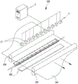
Fig. 1 is a schematic structural diagram of a system for rapidly detecting surface defects of a thin film according to an embodiment of the present application.
FIG. 2 is a schematic side view of the system for rapidly detecting surface defects of the thin film shown in FIG. 1.
Figures 3a-3f show examples of pictures of film surface defects before and after steam fumigation, respectively.
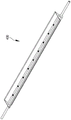
Fig. 4 is a perspective view schematically illustrating a steam spraying device according to an embodiment of the present application.
Fig. 5 is an exploded perspective view showing a steam spray device according to another embodiment of the present application.
FIG. 6 shows a schematic cross-sectional view of a steam injection apparatus according to yet another embodiment of the present application.
Detailed Description
In order to more clearly understand the technical features, objects, and effects of the present application, embodiments of the present application will now be described with reference to the accompanying drawings. Wherein like parts are given like reference numerals.
As mentioned in the background, some unobvious surface defects on a thin film are not easily found in the prior art, and therefore, the present application provides an improved system for rapidly detecting surface defects of a thin film, as shown in fig. 1-2, which respectively show a schematic structural diagram and a schematic side view structural diagram of a system for rapidly detecting surface defects of a thin film according to an embodiment of the present application.
As shown, the system for rapid detection of surface defects of thin films of the present application may include a part of CN 206740668U mentioned in the background, which is incorporated herein by reference as a part of the present application, and other similar embodiments can be obtained by those skilled in the art through reasonable derivation based on the disclosure of the prior art.
Specifically, the system for rapidly detecting the surface defects of the film can be used for detecting the surface defects of the film 100 through the detection device 500 after the film 100 passes through the stretching roller 200 and before the film enters the traction winding roller 300. The inspection apparatus 500 may be the film defect on-line inspection apparatus described in the prior art, or any other apparatus that can be used for visual inspection of surface defects.
The structure of one embodiment of the inspection apparatus 500 of the present application is illustrated below according to the thin film defect on-line inspection apparatus described in the foregoing prior art, but of course, a person skilled in the art can also retrieve other similar inspection apparatuses by reading the more detailed structure, function and principle of the inspection apparatus 500 described in the foregoing prior art, or derive other similar inspection techniques according to the description of the present application and the prior art.
In one embodiment, as shown, the inspection apparatus 500 that can be used in the present application includes a light source assembly 1 disposed below the film 100, an image capturing assembly 2 disposed above the film 100 opposite to the light source assembly 1, and a back-end server 3 connected to the image capturing assembly 2. In one embodiment, the image capturing assembly 2 comprises a plurality of high-speed cameras 21 arranged transversely to the direction of advance of the film 100, each high-speed camera 21 being connected to the back-end server 3 by an electric circuit. The basic working principle of the detection device 500 is: first, the film 100 is transmitted through the light emitted from the light source assembly 1, and then the film 100 is photographed through the image pickup assembly 2 above the film 100. If the film 100 has defective spots, such as so-called fish eyes, string dots, etc., the light below the film 100 does not completely penetrate the film 100 at the locations of these defective spots, and spots are formed on the picture taken by the image capturing assembly 2, and the locations without defects are only the color of the light source on the picture. The pictures obtained by the image acquisition assembly 2 are transmitted to the back-end server 3 on line in real time through a circuit, and the shooting time of each picture is also transmitted to the back-end server 3. Further, a meter counter (not shown) for measuring the length of the film 100 is provided on the take-up roll 300, and the meter counter and the take-up roll are operated in synchronization, and the value of the meter counter at the time of taking a photograph is also transmitted to the back-end server 3. After the photo is transmitted to the back-end server 3, the photo is recognized through recognition software running on the back-end server 3, if no defect exists, a pure white image is displayed, if the defect exists, a spot is formed on a white background, the size of the spot is recognized through the recognition software, for example, if the diameter of the spot is larger than a preset numerical value, the defect exists, the photo is automatically marked through the software, the shooting time and the size of the defect are recorded, the vertical and horizontal coordinates of the defect on the film 100 are determined through the shooting time, the corresponding meter counter and the position calculation of the high-speed camera 21, and the defect is located and recorded. If a large or regular defect is met, the production process, raw materials, equipment and the like possibly have faults, the alarm can be set through software, and the equipment can be shut down emergently after a defect photo is verified manually, so that loss caused by continuous waste in large quantities is avoided. Finally, after the number of defects of each batch and each roll of film products is verified, the film products can be graded and classified according to market consumption conditions.
As described in the background, the inspection apparatus 500 of the above embodiment is not effective in detecting some non-obvious surface defects on the film, and thus the present application is further improved on the basis of the above. As shown in the drawings, the rapid inspection system for surface defects of a film of the present application further includes a steam injection device 400 for injecting steam to the film 100, which is disposed between the stretching roll 200 and the inspection apparatus 500. That is, the present application is based on the prior art and adds a step of spraying steam to the film 100 before the film 100 is inspected.
The basic working principle of the application is as follows: before the film is detected, steam is sprayed to the film and is attached to the surface of the film through steam condensation, tiny defects on the surface of the film can be strengthened, the defects can become more obvious under the fumigation of the steam, the defects can be detected by subsequent detection equipment more easily, and the detection accuracy and efficiency are improved.
Figures 3a-3f show examples of pictures of film surface defects before and after steam fumigation, respectively, wherein figures 3a, 3c, 3e are images before steam fumigation and figures 3b, 3d, 3f show images after steam fumigation, respectively, corresponding to figures 3a, 3c, 3 e. It is evident that the formation of a significant texture on the surface of the film after fumigation makes it easy to discern the pattern and texture of the defects which would otherwise be difficult to show without fumigation.
Further, in order to obtain better adhesion development effect, the steam of the present application may be formed by evaporating the following mixed solution in parts by weight: 80-100 parts of distilled water, 10-15 parts of sodium alkyl benzene sulfonate, 20-30 parts of ethanol and 1-2 parts of polydimethylsiloxane.
The following table corresponds to the composition of the mixed solutions used in fig. 3b, 3d, 3f, respectively.

It can be seen from fig. 3b, 3d, and 3f that the above-mentioned components can achieve good developing effect when applied to the present application.
In addition, as shown, it is preferable that the steam be sprayed onto the film 100 from below the film to facilitate the excess condensate to leave the surface of the film as soon as possible, thereby avoiding the formation of a running watermark on the film. Of course, it is also possible to arrange for the steam to be injected into the film from other directions, since the steam is after all a lean gas with a low water content. If the film surface temperature is too low, condensation watermarks may form, and of course, the film surface temperature is generally relatively high when the film is stretched, and the chance of condensation of the dilute vapor is not very great, so that even steam injection into the film from above may be an acceptable solution.
Specific embodiments of the steam injection apparatus of the present application will be further described with reference to fig. 4 to 6. Which respectively show a perspective view, an exploded perspective view and a cross-sectional view of a steam spraying device according to an embodiment of the present application.
As shown, the steam spray device 400 of the present application may include at least one steam pipe 401 having a plurality of tapped holes 4011 and a steam cover 402 fixedly coupled to the steam pipe 401 by a plurality of screw joints 403.
The steam pipe 401 includes a working pipe with a large diameter in the middle and steam inlet pipes with small diameters at both sides, and high-temperature steam can be introduced into the working pipe from both ends through the steam inlet pipes, or steam can be introduced from one end, and the steam with a reduced temperature can be circularly guided back to the steam boiler (not shown in the figure) from the other end. The working tube is provided with a row of a plurality of threaded holes 4011 for connection to the nipple 403.
Steam may be generated by means known in the art and directed through a conduit into the steam pipe 401, for example, steam may be generated by a steam boiler. Further, the pressure, temperature, and flow rate of the steam supplied to steam pipe 401 may be adjusted several times in accordance with actual operations by using a known pressure gauge, thermometer, flowmeter, or the like until defects on the surface of the film are displayed remarkably.
The steam hood 402 is used to surround the steam jet within a certain range and spray the steam against the film 100, so that the sprayed steam can reach the film 100 as uniformly as possible. In addition, when the steam spraying device 400 is disposed below the film 100 as shown in fig. 2, the steam hood 402 can also be used to catch the cooling liquid falling from the steam condensation, so as to prevent the cooling liquid from gathering on the film to form a flowing water mark.
As can be seen from fig. 6 in detail, both ends of the threaded joint 403 are provided with external threads, and the middle part is provided with a flange 4031; the lower end of the threaded connector 403 is in threaded connection with a threaded hole 4011 of the steam pipe 401, and the upper end of the threaded connector passes through a light hole 4021 on the steam cover 402 and is connected with the nut 405. The center of the longitudinal axis of the threaded joint 403 is provided with an injection hole 4032 with a reduced middle part and enlarged two ends, and the injection hole 4032 with the structure can accelerate the flow velocity of air flow and disperse injected steam so as to reduce the volume of liquid drops in the steam, avoid the formation of condensed water as much as possible and be beneficial to obtaining a more uniform steam film.
The steam cover 402 has a substantially W-shaped cross section, and a platform 4022 contacting the flange 4031 of the screw connector 403 is formed in the middle thereof, and a groove 4023 is formed on each of both sides of the platform 4022. Steam cover 402 with a W-shaped cross section may be as shown in fig. 6, and the outer sides of the bottoms of grooves 4023 of steam cover 402 abut against the outer surface of steam pipe 401, so that steam cover 402 may be balanced on steam pipe 401, and steam cover 402 may be prevented from twisting and swinging under the action of the air flow. This is because the steam cover 402 has a large volume and can be made of only thin-walled metal, and therefore has a small rigidity, and by making the steam cover in a W-shaped cross section, not only can a greater rigidity be obtained, but also a bottom structure that wraps the steam pipe 401 can be obtained, and the steam cover has a better stability, and at the same time, grooves 4023 on both sides can be obtained for containing dripping condensed water. In one embodiment, the slots 4023 of the steam hood 402 may be connected to a diversion conduit (not shown) to facilitate the diversion of condensed water dripping into the slots 4023.
To avoid condensate leakage and air leakage, in one embodiment, a rubber gasket 404 may be provided between the nut 405 and the steam hood 402. Of course, since the position of the nut 405 is high, there is a low chance that a large amount of liquid will leak, and the rubber gasket 404 is provided to prevent the steam cover 402 from leaking at the installation position, so as to enhance the effect of the steam forward-spraying film formation.
In another embodiment, flat portions 4024 are formed at the distal edge of steam cover 402 by bending and forming the flat portions 4024 parallel to the surface of the membrane, and the flat portions 4024 may be attached to a soft felt (not shown) to prevent the distal edge of steam cover 402 from contacting the membrane and forming scratches.
It should be appreciated by those skilled in the art that while the present application is described in terms of several embodiments, not every embodiment includes only a single embodiment. The description is thus given for clearness of understanding only, and it is to be understood that all matters in the embodiments are to be interpreted as including all technical equivalents which are encompassed by the claims and are to be interpreted as combined with each other in a different embodiment so as to cover the scope of the present application.
The above description is only illustrative of the present invention and is not intended to limit the scope of the present invention. Any equivalent alterations, modifications and combinations that may be made by those skilled in the art without departing from the spirit and principles of this application shall fall within the scope of this application.
Claims (10)
1. A method for rapidly detecting surface defects of a film (100) after the film (100) passes through a stretching roller (200) and before the film enters a traction winding roller (300), and is characterized by comprising the following steps: before inspecting the film (100), steam is sprayed to the film (100).
2. The method of claim 1, wherein the steam is formed by evaporating a mixed solution of the following parts by weight: 80-100 parts of distilled water, 10-15 parts of sodium alkyl benzene sulfonate, 20-30 parts of ethanol and 1-2 parts of polydimethylsiloxane.
3. The method of claim 1, wherein the steam is sprayed onto the film (100) from below the film (100).
4. The method of claim 1, further comprising the step of drying the film (100) after the detecting.
5. A rapid detection system for surface defects of a film, which is used for detecting the surface defects of the film (100) through a detection device (500) after the film (100) passes through a stretching roller (200) and before the film enters a traction winding roller (300), and is characterized in that the rapid detection system for surface defects of the film further comprises a steam injection device (400) which is arranged between the stretching roller (200) and the detection device (500) and injects steam to the film (100).
6. The rapid detection system of claim 5, wherein the steam injection device (400) comprises at least one steam pipe (401) having a plurality of tapped holes (4011) and a steam cover (402) fixedly attached to the steam pipe (401) by a plurality of threaded joints (403).
7. The rapid detection system according to claim 6, wherein both ends of the threaded joint (403) are provided with external threads, and the middle part is provided with a flange (4031); the lower end of the threaded connector (403) is in threaded connection with a threaded hole (4011) of the steam pipe (401), and the upper end of the threaded connector penetrates through a unthreaded hole (4021) in the steam cover (402) and is connected with a nut (405).
8. The rapid detection system of claim 7, wherein the steam hood (402) is W-shaped in cross section, a platform (4022) contacting the flange (4031) of the threaded connector (403) is formed in the middle, and a groove (4023) is formed on each side of the platform (4022).
9. The rapid detection system of claim 8, wherein the bottom outer side of the groove (4023) of the steam cover (402) abuts against the outer surface of the steam pipe (401).
10. The rapid detection system of claim 6, characterized in that the steam cover (402) is bent at its distal edge to form a flat portion (4024) parallel to the surface of the membrane, and a soft felt is fixed to the surface of the flat portion (4024).
Priority Applications (1)
| Application Number | Priority Date | Filing Date | Title |
|---|---|---|---|
| CN202111010419.1A CN113686877B (en) | 2021-08-31 | 2021-08-31 | Method and system for rapidly detecting surface defects of film |
Applications Claiming Priority (1)
| Application Number | Priority Date | Filing Date | Title |
|---|---|---|---|
| CN202111010419.1A CN113686877B (en) | 2021-08-31 | 2021-08-31 | Method and system for rapidly detecting surface defects of film |
Publications (2)
| Publication Number | Publication Date |
|---|---|
| CN113686877A true CN113686877A (en) | 2021-11-23 |
| CN113686877B CN113686877B (en) | 2024-05-07 |
Family
ID=78584310
Family Applications (1)
| Application Number | Title | Priority Date | Filing Date |
|---|---|---|---|
| CN202111010419.1A Active CN113686877B (en) | 2021-08-31 | 2021-08-31 | Method and system for rapidly detecting surface defects of film |
Country Status (1)
| Country | Link |
|---|---|
| CN (1) | CN113686877B (en) |
Cited By (2)
| Publication number | Priority date | Publication date | Assignee | Title |
|---|---|---|---|---|
| US20230077585A1 (en) * | 2021-09-15 | 2023-03-16 | TE Connectivity Services Gmbh | Method and apparatus for flattening and imaging a printed thin film product |
| CN117388316A (en) * | 2023-12-11 | 2024-01-12 | 瑞金市金联机械有限公司 | Raw material defect detection and marking equipment on aluminum film balloon machine |
Citations (7)
| Publication number | Priority date | Publication date | Assignee | Title |
|---|---|---|---|---|
| JP2014219222A (en) * | 2013-05-01 | 2014-11-20 | 住友電気工業株式会社 | Defect inspection method for cast material |
| CN104317077A (en) * | 2014-10-22 | 2015-01-28 | 合肥京东方光电科技有限公司 | Alignment layer detection machine |
| CN106556608A (en) * | 2016-07-14 | 2017-04-05 | 苏州新材料研究所有限公司 | A kind of method and system of detection surface defects of products |
| CN109001231A (en) * | 2018-10-15 | 2018-12-14 | 芜湖东旭光电装备技术有限公司 | A kind of surface defects detection equipment |
| CN212227311U (en) * | 2020-06-01 | 2020-12-25 | 广东美的暖通设备有限公司 | Steam pipe assembly and air conditioner |
| CN112255242A (en) * | 2020-08-24 | 2021-01-22 | 重庆神华薄膜太阳能科技有限公司 | Surface defect detection system and detection method |
| CN215866473U (en) * | 2021-08-31 | 2022-02-18 | 江苏双星彩塑新材料股份有限公司 | Rapid detection system for film surface defects |
-
2021
- 2021-08-31 CN CN202111010419.1A patent/CN113686877B/en active Active
Patent Citations (7)
| Publication number | Priority date | Publication date | Assignee | Title |
|---|---|---|---|---|
| JP2014219222A (en) * | 2013-05-01 | 2014-11-20 | 住友電気工業株式会社 | Defect inspection method for cast material |
| CN104317077A (en) * | 2014-10-22 | 2015-01-28 | 合肥京东方光电科技有限公司 | Alignment layer detection machine |
| CN106556608A (en) * | 2016-07-14 | 2017-04-05 | 苏州新材料研究所有限公司 | A kind of method and system of detection surface defects of products |
| CN109001231A (en) * | 2018-10-15 | 2018-12-14 | 芜湖东旭光电装备技术有限公司 | A kind of surface defects detection equipment |
| CN212227311U (en) * | 2020-06-01 | 2020-12-25 | 广东美的暖通设备有限公司 | Steam pipe assembly and air conditioner |
| CN112255242A (en) * | 2020-08-24 | 2021-01-22 | 重庆神华薄膜太阳能科技有限公司 | Surface defect detection system and detection method |
| CN215866473U (en) * | 2021-08-31 | 2022-02-18 | 江苏双星彩塑新材料股份有限公司 | Rapid detection system for film surface defects |
Cited By (4)
| Publication number | Priority date | Publication date | Assignee | Title |
|---|---|---|---|---|
| US20230077585A1 (en) * | 2021-09-15 | 2023-03-16 | TE Connectivity Services Gmbh | Method and apparatus for flattening and imaging a printed thin film product |
| US11867639B2 (en) * | 2021-09-15 | 2024-01-09 | Te Connectivity Solutions Gmbh | Method and apparatus for flattening and imaging a printed thin film product |
| CN117388316A (en) * | 2023-12-11 | 2024-01-12 | 瑞金市金联机械有限公司 | Raw material defect detection and marking equipment on aluminum film balloon machine |
| CN117388316B (en) * | 2023-12-11 | 2024-03-15 | 瑞金市金联机械有限公司 | Raw material defect detection and marking equipment on aluminum film balloon machine |
Also Published As
| Publication number | Publication date |
|---|---|
| CN113686877B (en) | 2024-05-07 |
Similar Documents
| Publication | Publication Date | Title |
|---|---|---|
| CN215866473U (en) | Rapid detection system for film surface defects | |
| CN113686877A (en) | Method and system for rapidly detecting surface defects of thin film | |
| CN105044121B (en) | A kind of online defect detection device of circular knitting machine and detection method | |
| AU2007351270B2 (en) | Method for inspecting defect of hollow fiber porous membrane, defect inspection equipment and production method | |
| KR20180011011A (en) | Infrared non-destructive evaluation of cooling holes using evaporative membrane | |
| DE602005006232D1 (en) | Device for producing hoses and corresponding method for fault detection | |
| JP5842373B2 (en) | Surface defect detection method and surface defect detection apparatus | |
| CN206891990U (en) | A kind of surface defects of products on-line measuring device | |
| CN110646376A (en) | Lens defect detection method based on fringe deflection | |
| CN104317077B (en) | A kind of alignment films detection machine | |
| CN118681823B (en) | PCB hydrophobicity test system and test method | |
| CN117491254A (en) | Tobacco tar diffusivity test method and device for oil-guiding cotton | |
| CN113793321A (en) | Casting surface defect dynamic detection method and device based on machine vision | |
| CN115615998B (en) | Circular magnetic core side defect detection device and method | |
| CN106500931B (en) | The detection device and detection method of on-condensible gas in a kind of steam | |
| CN208121445U (en) | A kind of cloth inspecting machine that can be calibrated automatically | |
| CN105371955A (en) | Dyeing color difference detection device and method | |
| CN117805108A (en) | Non-contact hollow fiber membrane integrity detection device | |
| CN216821720U (en) | Multi-dimensional monitoring system for nozzle atomization of tobacco primary processing line | |
| CN116862855B (en) | A method and system for monitoring leakage in a water-lubricated tail shaft based on image processing | |
| CN114897784B (en) | Monocular egg size assembly line measuring method | |
| KR101098454B1 (en) | Inspection method of photoresist coating process using image processing and inspection system of photoresist coating process used therein | |
| CN208121443U (en) | A kind of cloth inspecting machine | |
| CN114624150B (en) | A contact angle measurement method that simultaneously measures and verifies each other at the micro and macro levels | |
| CN213875350U (en) | Device for detecting concentration of particles in high-speed fluid |
Legal Events
| Date | Code | Title | Description |
|---|---|---|---|
| PB01 | Publication | ||
| PB01 | Publication | ||
| SE01 | Entry into force of request for substantive examination | ||
| SE01 | Entry into force of request for substantive examination | ||
| GR01 | Patent grant | ||
| GR01 | Patent grant |