CN113686775A - Measuring device and method for measuring buoyancy loss of solid buoyancy material - Google Patents
Measuring device and method for measuring buoyancy loss of solid buoyancy material Download PDFInfo
- Publication number
- CN113686775A CN113686775A CN202010421219.4A CN202010421219A CN113686775A CN 113686775 A CN113686775 A CN 113686775A CN 202010421219 A CN202010421219 A CN 202010421219A CN 113686775 A CN113686775 A CN 113686775A
- Authority
- CN
- China
- Prior art keywords
- test
- cylinder
- pressure
- medium
- bin
- Prior art date
- Legal status (The legal status is an assumption and is not a legal conclusion. Google has not performed a legal analysis and makes no representation as to the accuracy of the status listed.)
- Pending
Links
Images


Classifications
-
- G—PHYSICS
- G01—MEASURING; TESTING
- G01N—INVESTIGATING OR ANALYSING MATERIALS BY DETERMINING THEIR CHEMICAL OR PHYSICAL PROPERTIES
- G01N19/00—Investigating materials by mechanical methods
Landscapes
- Physics & Mathematics (AREA)
- Health & Medical Sciences (AREA)
- Life Sciences & Earth Sciences (AREA)
- Chemical & Material Sciences (AREA)
- Analytical Chemistry (AREA)
- Biochemistry (AREA)
- General Health & Medical Sciences (AREA)
- General Physics & Mathematics (AREA)
- Immunology (AREA)
- Pathology (AREA)
- Investigating Strength Of Materials By Application Of Mechanical Stress (AREA)
Abstract
The invention discloses a measuring device and a method for measuring buoyancy loss of a solid buoyancy material. The measuring device comprises: the device comprises a test bin, a pre-charging system, a pressurization system and a measurement control system; one end of the pre-charging system is connected with the inlet end of the test bin through a pressurization system, and the other end of the pre-charging system is connected with the outlet end of the test bin; and the measurement control system is respectively connected with the pre-charging system and the pressurization system. The buoyancy loss of the buoyancy material is calculated by measuring the volume difference of the pressed water in the test bin which is provided with the standard sample and the buoyancy material sample to be tested under certain pressure. The invention has the advantages of accurate measurement result, high measurement precision, stable and accurate pressure maintaining, simple and easy operation and the like, can measure the buoyancy loss of the buoyancy material under a series of pressure intensity by one-time measurement, and effectively improves the measurement efficiency. The device is reliable, the measurement process is simple and easy to implement, and the buoyancy loss of the buoyancy material under different hydrostatic pressures can be continuously measured.
Description
Technical Field
The invention belongs to the technical field of buoyancy loss measurement of solid buoyancy materials, and particularly relates to a measuring device and a method for measuring buoyancy loss of a solid buoyancy material.
Background
The solid buoyancy material is a key core material in ocean exploration and deep sea engineering, can bear hydrostatic pressure in a deep sea environment, can provide buoyancy for an underwater device, plays a role in buoyancy compensation, and achieves the functions of suspension positioning, unpowered floating and submerging, effective load increase and overall dimension reduction of the deep sea device.
The solid buoyancy material is applied to the deep sea high water pressure environment, on one hand, the solid buoyancy material can cause the self water absorption, and on the other hand, the solid buoyancy material can cause the volume contraction, so that the buoyancy loss is caused. The buoyancy loss of the solid buoyancy material in the service water depth is accurately measured, and the buoyancy provided by the solid buoyancy material in the practical application can be obtained. The buoyancy loss of the solid buoyancy material under different water depths is different, and the provided effective buoyancy is also different, which relates to the integral buoyancy, effective load and counterweight of the deep submergence device at different depths. Therefore, the accurate measurement of the buoyancy loss of the solid buoyancy material under high water pressure plays an important role in guaranteeing the safety and reliability of the deep submergence vehicle.
The method measures the strain of the strain gauge on the batten beam suspending the buoyancy material and the counterweight under no pressure and high water pressure respectively, converts the strain into stress change, and obtains the buoyancy loss of the buoyancy material through calculation. For example, patent document (application No. 200810022677.X) discloses a buoyancy loss measuring device and method for a buoyancy material under high hydrostatic pressure. The device is characterized in that a plate beam and a barrel cover are connected through two suspension rods, strain gauges are attached to the upper surface and the lower surface of the middle of the plate beam, a cable of each strain gauge penetrates through a cable hole in the barrel cover to be connected with a strain gauge, and a buoyancy material and a ballast block are suspended on the strain gauges below the plate beam through ropes. During measurement, strain of the strain gauge of the buoyancy material under no pressure and high water pressure is measured, and the strain is converted into stress, so that the buoyancy loss of the buoyancy material is calculated. This method has the following drawbacks: 1. according to the method, the buoyancy material and the ballast block are suspended by the two suspension rods and the connecting plate bar beam, the gravity centers of the buoyancy material and the ballast block on the bar beam are difficult to find accurately, if the gravity centers shift, radial stress is generated, the strain of the strain gauge is inaccurate, and the buoyancy loss measurement is inaccurate. 2. According to the method, the strain gauge and the strain gauge are connected through the cable, a cable hole needs to be processed in the cylinder cover, and the cable penetrates through the cable hole to connect the strain gauge and the strain gauge, so that the maintenance of high hydrostatic pressure and the reliability of the device are not facilitated. 3. The loss of buoyancy of a solid buoyant material is generally small, resulting in a strain gauge that is also small, which requires a high degree of precision in the strain gauge. In addition, the effect of high hydrostatic pressure on the strain of the strain gauge and its accuracy needs to be further demonstrated. 4. In the method, the selection and calibration of the plank beam sample, the measurement of strain and the conversion of stress are required in the test process, the process is complex, and the operation is inconvenient.
Patent document (application No. 201811569359.5) discloses a measurement method for simulating buoyancy loss of a buoyancy material in a deep sea environment, which is an improvement on the above method. The method cancels the use of two suspenders and a batten beam, directly pastes a strain gauge on a pull rod connected with a frame for placing the buoyancy material and a balance weight, obtains the change of the axial stress of the pull rod by respectively measuring the strain of the strain gauge under no pressure and test water pressure, and calculates the buoyancy loss of the buoyancy material. Although an improvement is made, the principle of the method is still based on a strain gauge method. According to the method, the strain gauge is attached to a pull rod connected with a frame for placing the buoyancy material and the balance weight, and if the centers of gravity of the buoyancy material, the frame and the balance weight are not in the same straight line, the pull rod can generate radial stress to influence the strain of the strain gauge, so that the buoyancy loss measurement is inaccurate. Further, this method has the drawbacks described in the above patent documents as point 2 and point 3.
Disclosure of Invention
The invention provides a device and a method for measuring buoyancy loss of a solid buoyancy material, aiming at overcoming the defects of inaccurate measurement, limited measurement precision, unstable hydrostatic pressure, complex operation and the like of the conventional device and method for measuring buoyancy loss of the solid buoyancy material.
In order to solve the problems, the invention adopts the following technical scheme:
a solid buoyant material buoyancy loss measurement apparatus, the apparatus comprising: the device comprises a test bin, a pre-charging system, a pressurization system and a measurement control system;
one end of the pre-charging system is connected with one end (inlet) of the test bin through a pressurization system, and the other end of the pre-charging system is connected with the other end (outlet) of the test bin;
and the measurement control system is respectively connected with the pre-charging system and the pressurization system.
According to an embodiment of the invention, the priming system comprises a test medium which can enter and fill the test chamber through a pressurization system.
According to an embodiment of the present invention, the pressurization system is configured to deliver the test media to the test chamber to pressurize the test chamber. For example, the test medium may be water or saline, preferably water.
According to an embodiment of the invention, the test chamber contains a standard sample or a sample of the buoyant material to be tested. Wherein, the standard sample is made of stainless steel. The buoyancy material sample to be detected is a solid buoyancy material, such as a solid buoyancy material prepared by mixing and thermally curing hollow glass beads and a polymer.
According to the embodiment of the invention, the test bin comprises a test cylinder, a test cylinder cover and a test tool, wherein the test tool is arranged in the test cylinder and used for loading and fixing a standard sample or a buoyancy material sample to be tested; the testing cylinder cover is used for being matched with the testing cylinder to form a closed testing bin.
According to the embodiment of the invention, the test chamber can bear the hydrostatic pressure of 100MPa-200MPa, and the person skilled in the art can understand that the hydrostatic pressure which can be borne by the test chamber can be selected according to the test requirement.
Wherein, the material of test jar is stainless steel material.
The testing cylinder is a cylinder with an accommodating cavity, preferably a cylinder, and the accommodating cavity is used for accommodating a testing tool. Further, the test cylinder is cylindrical, the inner diameter of the test cylinder is 50mm-400mm, and the outer diameter of the test cylinder is 150mm-600 mm.
The bottom of the testing cylinder is provided with a first opening, and the first opening is connected with the pressurization system to provide an inlet for a testing medium.
And a third open hole is formed in the testing cylinder cover (preferably at the circle center of the testing cylinder cover), is connected with the pre-charging system and is used for discharging air in the testing bin when testing media are pre-charged and circularly returning the testing media to the pre-charging system.
According to the embodiment of the invention, the appearance of the test tool is matched with the accommodating cavity. For example, the accommodating cavity is cylindrical, and the test tool is also cylindrical in shape.
The test tool is provided with a groove, and the groove is used for accommodating a standard sample or a buoyancy material sample to be tested. For example, the groove may be a rectangular parallelepiped or a square or cylindrical groove. Preferably, the shape of the standard sample or the buoyancy material sample to be tested is matched with the shape of the groove.
Preferably, the test fixture is tightly matched with the test cylinder, and the test fixture groove is tightly matched with the standard sample or the buoyancy material to be tested.
Preferably, the outer diameter of the test tool is 1-4mm smaller than the inner diameter of the test cylinder, so that the test tool is conveniently installed in the test cylinder, and the gap between the test cylinder and the test tool is conveniently filled with pre-filled water.
Preferably, the size of the inner groove of the test tool is 1-4mm larger than that of the standard sample or the buoyancy material to be tested, so that the standard sample or the buoyancy material to be tested can be conveniently loaded into the test tool, and the gap between the test tool and the standard sample or the buoyancy material to be tested can be conveniently filled with pre-filled water.
And a second opening is formed in the bottom of the test tool and communicated with the first opening. And the second opening is connected with the pressurization system to provide an inlet for a test medium.
The testing tool is used for loading and fixing the position of a standard sample or a buoyancy material sample to be tested. Furthermore, the testing tool has the function of reducing the addition of a pre-filled testing medium as much as possible, so that the measuring result is accurate.
Wherein, the standard sample is made of stainless steel.
And the standard sample and the buoyancy material sample to be detected have the same size.
The shape of the standard sample is the same as that of the groove of the test tool, such as a cuboid, a cube or a cylinder.
Wherein, the size of the standard sample can be determined according to the sizes of the testing cylinder and the testing tool.
According to an embodiment of the invention, the pre-fill system comprises a constant temperature circulating test media tank, a gas driven booster pump.
According to the embodiment of the invention, one end of the gas-driven booster pump is connected with the constant-temperature circulating test medium box, and the other end of the gas-driven booster pump is connected with a boosting system.
According to an embodiment of the present invention, the constant temperature cycle test medium box contains a test medium, and those skilled in the art will understand that the volume of the constant temperature cycle test medium box and the temperature constant range thereof are not particularly limited. For example, the constant temperature cycle test media box has a volume of 5L to 20L. For example, the temperature of the test media in the constant temperature cycle test media box ranges from 10 ℃ to 50 ℃. The temperature of the testing medium in the constant-temperature circulating testing medium box is constant and can be adjusted according to setting.
The constant-temperature circulation test medium box mainly functions to provide a constant-temperature test medium source for pre-filled test medium and pressurized test medium. The test medium entering the pressurizing system and the test bin is at a constant temperature, and then the pressurizing system and the test bin are in a constant temperature environment. Constant temperature test media can provide accurate measurement results because the density of the test media is related to its temperature.
According to the embodiment of the invention, the gas-driven booster pump can utilize the pressure of the gas medium to press the test medium in the constant-temperature circulating test medium box into the booster system through the pipeline and then to the test chamber, so as to pre-fill the test chamber with the test medium. The pressure of the gas-driven booster pump is 4-8 atmospheric pressures.
According to an embodiment of the invention, the priming system further comprises a priming medium vent valve, a gaseous medium inlet, a filter, a gaseous medium shut-off valve, and a priming medium shut-off valve.
According to the embodiment of the invention, one end of the gas-driven booster pump is communicated with the gas medium inlet, and a filter and a gas medium stop valve are arranged between the gas medium inlet and the gas-driven booster pump. Wherein the gaseous medium may be air. Preferably, the gaseous medium inlet may be vented with air. The filter may filter contaminants from the incoming gaseous medium (e.g., air). The gas medium stop valve is arranged between the filter and the gas-driven booster pump and used for controlling the introduction of the gas medium.
According to the embodiment of the invention, the other end of the gas-driven booster pump is connected with the boosting system, and preferably, a pre-filling test medium stop valve is arranged between the other end of the gas-driven booster pump and the boosting system. The pre-charging test medium stop valve is opened when the test medium is pre-charged and closed before the test is started.
According to an embodiment of the present invention, the gas medium inlet, the filter, the gas medium stop valve, the gas-driven booster pump, the pre-charge test medium stop valve, and the booster system are arranged in this order.
According to an embodiment of the present invention, a pre-filled test media vent valve is provided between the constant temperature circulating test media tank and the test chamber. When the device is used for pre-charging the testing medium, the testing bin is exhausted, and the pre-charged testing medium can return to the constant-temperature circulating testing medium box through the exhaust valve, so that the internal temperature of the testing device is consistent with the temperature of the pre-charged water.
According to the embodiment of the invention, one end of the pre-charging test medium exhaust valve is connected with the test cylinder cover, and the other end of the pre-charging test medium exhaust valve is connected with the constant-temperature circulation test medium box.
According to an embodiment of the invention, the pressurization system comprises a servo electric cylinder, a high-pressure pressurization cylinder; one end of the high-pressure booster cylinder is connected with the test bin, the other end of the high-pressure booster cylinder is connected with the pre-charging system, the other end of the high-pressure booster cylinder is connected with the servo electric cylinder, and the servo electric cylinder is used for boosting the high-pressure booster cylinder and the test bin; preferably, the servo electric cylinder pressurizes the high-pressure pressurizing cylinder and the test bin through thrust.
According to the embodiment of the invention, the high-pressure booster cylinder is connected with the air-driven booster pump, and a pre-filled test medium stop valve and a pressure sensor are arranged between the high-pressure booster cylinder and the air-driven booster pump. Preferably, the pressure sensor is located proximate to the high pressure booster cylinder.
Preferably, the pressurization system further comprises a pressure relief valve, and the pressure relief valve is arranged between the constant-temperature test medium tank and the high-pressure pressurization cylinder. Preferably, one end of the pressure relief valve is arranged between the pre-charging test medium stop valve and the pressure sensor, and the other end of the pressure relief valve is connected with the constant-temperature circulation test medium box. The main function of the pressure relief valve is to operate the pressure relief valve to relieve pressure of the test bin when the servo electric cylinder has a problem and cannot relieve pressure. Typically, the pressure relief valve is normally closed.
According to an embodiment of the invention, the flow path of the test medium in the constant temperature cycle test medium box in the device is: constant temperature cycle test medium box → air-driven booster pump → high pressure booster cylinder → test chamber → constant temperature cycle test medium box.
According to the embodiment of the invention, the test bin, the high-pressure booster cylinder and the pipeline connected with the high-pressure booster cylinder can be wrapped by the heat insulation cotton, so that the measured temperature is more constant.
According to an embodiment of the invention, the measurement control system comprises a control terminal for controlling the pre-charging of the test medium and the pressurizing of the test medium. Preferably, the control end is connected with a pre-charging test medium exhaust valve, a gas medium stop valve, a gas-driven booster pump, a pre-charging test medium stop valve, a pressure sensor and a servo electric cylinder respectively.
The pressure sensor can record the pressure applied to the test bin in real time. The servo electric cylinder can set a propelling speed and a return speed through the control end, the test bin is controlled to be pressurized through the propelling speed, and the test bin is controlled to be released through the return speed. The servo electric cylinder can record a stroke, and the positioning precision is 0.01 mm. The volume of water pushed into the test bin by the servo electric cylinder is equal to the square of the stroke of the servo electric cylinder multiplied by pi multiplied by the radius of the high-pressure booster cylinder.
The control end displays a two-dimensional image of a test result, the abscissa is the volume of water pushed into the test bin by the servo electric cylinder, and the ordinate is the pressure in the test bin.
Preferably, the control end comprises a control program, and the braking of each part is controlled through the control program.
The invention also provides a method for measuring the buoyancy loss of the solid buoyancy material by using the device for measuring the buoyancy loss of the solid buoyancy material, which comprises the following steps:
(A) and (3) testing a reference curve:
(i) loading a standard sample: putting the standard sample into a test bin, and sealing the test bin;
(ii) the test chamber is pre-filled with test media: filling the test bin with a test medium, so that the temperature of the standard sample, the high-pressure booster cylinder and the test bin is the same as the temperature of the test medium;
(iii) and (3) testing a reference curve: pushing a test medium into a high-pressure pressurizing cylinder and a test bin through a servo electric cylinder for pressurizing, maintaining the pressure after the maximum pressure is reached, and then releasing the pressure until the pressure is 0 to obtain a volume change curve of a standard sample pressed into the test medium in a test pressure range, wherein the volume change curve is used as a reference curve;
the volume of water pushed into the test bin by the servo electric cylinder is equal to the square of the stroke of the servo electric cylinder multiplied by pi multiplied by the radius of the high-pressure booster cylinder;
(B) testing the solid buoyancy material to be tested:
putting the solid buoyancy material to be tested into a test bin, and sealing the test bin;
repeating the steps (A) (ii), (A) (iii) to obtain a volume change curve of the solid buoyancy material to be tested pressed into the test medium in the test pressure range, and taking the volume change curve as a sample curve to be tested;
(C) calculation of buoyancy loss: and obtaining the volume difference delta V of the test medium in the test bin under the same pressure by using the reference curve and the curve of the sample to be tested, thereby calculating and obtaining the buoyancy loss of the solid buoyancy material to be tested.
According to an embodiment of the invention, in step (A) (ii), the time for pre-charging the test medium is 10-30min, for example 15-20 min. For example, the temperature of the test medium can be adjusted as desired, for example, from 15 to 40 deg.C, and, for example, from 25 to 30 deg.C.
According to the embodiment of the invention, in the step (A) (ii), when the testing medium is pre-filled, the gas medium stop valve, the pre-filled testing medium stop valve and the pre-filled testing medium exhaust valve are opened, the gas-driven booster pump is opened, the testing medium in the constant-temperature circulating testing medium box flows through the gas-driven booster pump, flows through the high-pressure booster cylinder, enters the testing bin, returns to the constant-temperature circulating water box through the pre-filled testing medium exhaust valve, lasts for 10-30min, and the temperatures of the standard sample, the high-pressure booster cylinder and the testing bin are all adjusted to be the same as the temperature of the testing medium; and after the test medium is pre-filled, the gas-driven booster pump is closed, and the gas medium stop valve, the pre-filling test medium stop valve and the pre-filling test medium exhaust valve are closed.
According to an embodiment of the invention, in step (a) (iii), the dwell time is 5-30min, such as 10-20 min.
According to an embodiment of the invention, in step (a) (iii), the maximum pressure does not exceed 200 MPa. Preferably, the pressure relief may be gradual.
According to an embodiment of the invention, the maximum thrust of the servo cylinder is in the range of 100KN-200KN, e.g. 120KN-180 KN. Wherein the stroke range of the servo electric cylinder can be 100mm-500mm, such as 200mm-400 mm. Wherein the speed range of the servo electric cylinder is 0.1mm/min-10mm/min, such as 1mm/min-5 mm/min. For example, the propulsion speed of the servo electric cylinder is the same as or different from the return speed, preferably the same, such as 2 mm/min.
According to an embodiment of the invention, the stroke of the high pressure booster cylinder is greater than or equal to the stroke of the servo electric cylinder, and the stroke of the high pressure booster cylinder may range from 100mm to 600mm, such as from 200mm to 500 mm. The cylinder diameter range of the high-pressure booster cylinder is 10mm-100mm, such as 30mm-80 mm; the smaller the cylinder diameter, the higher the test accuracy. The maximum design pressure range of the high-pressure booster cylinder is 100MPa-300MPa, such as 150MPa-250MPa, and is selected according to the test requirement.
In the present invention, the test medium may be water or saline, preferably water. The gaseous medium may be air, nitrogen, or the like, preferably air.
According to an exemplary embodiment of the present invention, the measuring method comprises the steps of:
(1) loading a standard sample: placing the test tool into a test cylinder, placing the standard sample into the test tool, covering a test cylinder cover, fastening by using bolts, and sealing the test bin;
(2) pre-charging a test bin with water: opening a constant-temperature circulating water tank, setting the water temperature to be T, and preheating; pre-filling water for a test chamber through a control end, setting pre-filling time, opening an air stop valve, a pre-filling water stop valve and a pre-filling water exhaust valve, opening an air-driven booster pump, enabling water in a constant-temperature circulating water tank to flow through a high-pressure booster cylinder and enter the test chamber through the air-driven booster pump, and then returning the water to the constant-temperature circulating water tank through a pre-filling water exhaust valve, and adjusting the temperatures of circulating water, a standard sample, the high-pressure booster cylinder and the test chamber to be T within the pre-filling time; after the pre-charging is finished, the air-driven booster pump is closed, and the air stop valve, the pre-charging water stop valve and the pre-charging water exhaust valve are closed;
(3) and (3) testing a reference curve: setting the propelling speed, the return speed and the maximum pressure of the servo electric cylinder, and pushing water into the test bin through the servo electric cylinder for pressurization;
in the test process, a control end (such as computer software) can draw a two-dimensional image in real time (the ordinate is the pressure of a test bin, and the abscissa is the volume of water pushed into the test bin by a servo electric cylinder;
when the maximum pressure is reached, the pressure is maintained, and then the servo electric cylinder returns to release the pressure according to the set return speed until the pressure is 0; obtaining a volume change curve of the standard sample pressed into water in a range of 0-maximum pressure intensity, namely a reference curve;
(4) replacing a solid buoyancy material sample: opening a testing cylinder cover, taking out a standard sample, putting the solid buoyancy material to be tested into a testing bin, covering the testing cylinder cover, fastening by using bolts, and sealing the testing bin;
(5) and (3) testing the buoyancy material: repeating the steps (2) and (3) to obtain a volume change curve of the solid buoyancy material filled with the buoyancy material in the range of 0-maximum pressure intensity and the volume change curve of the water pressed in the test bin, namely a measurement curve;
(6) calculation of buoyancy loss: after the test is finished, the reference curve and the measurement curve are passed according to FLoss of buoyancy=ρT waterCalculating the buoyancy loss of the solid buoyancy material under any pressure within the range of 0-maximum pressure;
where ρ isT waterRepresents the density of water at a temperature T; g is the ratio of gravity to mass, and is taken as 9.8N/kg; the delta V is the volume difference of water pressed into the test bin under the same pressure when the test bin is respectively filled with the standard sample and the solid buoyancy material; preferably, Δ V is a difference between the abscissa and the abscissa of the reference curve and the measured curve at the same specific pressure.
The measurement principle of the method of the invention is as follows: the buoyancy loss of a solid buoyant material under high hydrostatic pressure comprises two parts: the self-absorption and volume contraction of the solid buoyant material. The buoyancy loss caused by the two factors can be calculated by the volume difference of water pushed into the test bins respectively containing the standard sample and the buoyancy material sample to be tested by the pressurization system under the given pressure, and the obtained buoyancy loss can be represented by the following formula:
Floss of buoyancy=ρT test medium×g×△V
△V=πr2△l
Where ρ isT test mediumThe density of the medium to be tested at a certain temperature can be obtained by looking up a table; g is the ratio of gravity to mass, and is taken as 9.8N/kg; the delta V is the volume difference of water pressed into the test bin under a specific pressure when the test bin is respectively filled with the standard sample and the buoyancy material sample to be tested; pi is the circumferential rate, r is the radius of the high-pressure booster cylinder, and delta l is the stroke difference of the servo electric cylinder under specific pressure when the test bin is respectively provided with the standard sample and the buoyancy material sample to be tested.
The invention also provides application of the measuring device and/or the method in measuring buoyancy loss of the solid buoyancy material. Preferably, the solid buoyancy material can be a solid buoyancy material prepared by mixing and thermally curing hollow glass beads and polymers.
The effective fruit of the present invention
Compared with the prior art that the buoyancy loss of the solid buoyancy material is measured by a strain gauge method, the buoyancy loss of the buoyancy material is calculated by measuring the volume difference of the pressurized water in a test bin which is provided with a standard sample and a buoyancy material sample to be measured under certain pressure. The invention has the advantages of accurate measurement result, high measurement precision, stable and accurate pressure maintaining, simple and easy operation and the like, can measure the buoyancy loss of the buoyancy material under a series of pressure intensity by one-time measurement, and effectively improves the measurement efficiency. The device is reliable, the measurement process is simple and easy to implement, and the buoyancy loss of the buoyancy material under different hydrostatic pressures can be continuously measured.
1. Different from the prior art strain gauge method, the invention can calculate the buoyancy loss of the solid buoyancy material by measuring the volume difference of water pressed into the test bin under certain pressure when the standard sample and the buoyancy material sample to be measured are filled in the test bin. Compared with a strain gauge method, the method can accurately measure the buoyancy loss of the solid buoyancy material, and has high measurement precision.
2. Compared with a strain gauge method, the invention has the advantages that no test cable passes through the test bin, and the stable, accurate and reliable test pressure intensity can be kept in the test bin in the test process.
3. Compared with a strain gauge method, the measuring method is simple and easy to implement, the measuring process is integrally controlled by the control end, and the operation process is simplified.
4. Compared with a strain gauge method, the method can measure the buoyancy loss of the buoyancy material under a series of pressures within the range from 0 to the maximum pressure through one-time measurement, and effectively improves the testing efficiency.
Drawings
FIG. 1 is a schematic view of a buoyancy loss measuring device of the solid buoyancy material in example 1.
FIG. 2 is a schematic cross-sectional view of the test chamber of FIG. 1.
Reference numerals: 1. the device comprises a test bin, 2. a pre-charging exhaust valve, 3. a constant-temperature circulating water tank, 4. an air inlet, 5. a filter, 6. an air stop valve, 7. an air-driven booster pump, 8. a pre-charging stop valve, 9. a pressure sensor, 10. a servo electric cylinder, 11. a high-pressure booster cylinder, 12. a pressure relief valve, 13. a test cylinder, 14. a test cylinder cover, 15. a test tool, 16. a standard sample/buoyancy material sample to be tested, and 17. a test medium inlet.
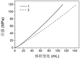
FIG. 3 is the test results of the reference curve and the measurement curve in example 2; where 1 represents the reference curve and 2 represents the measurement curve.
Detailed Description
The technical solution of the present invention will be further described in detail with reference to specific embodiments. It is to be understood that the following examples are only illustrative and explanatory of the present invention and should not be construed as limiting the scope of the present invention. All the technologies realized based on the above-mentioned contents of the present invention are covered in the protection scope of the present invention.
Unless otherwise indicated, the raw materials and reagents used in the following examples are all commercially available products or can be prepared by known methods.
Example 1
The buoyancy loss measuring device for the solid buoyancy material shown in fig. 1 comprises: the device comprises a test bin 1, a pre-charging system, a pressurizing system and a measurement control system, wherein one end of the pre-charging system is connected with the inlet end of the test bin through the pressurizing system, and the other end of the pre-charging system is connected with the outlet end of the test bin; and the measurement control system is respectively connected with the pre-charging system and the pressurization system.
As shown in fig. 2, the test chamber 1 includes a test cylinder 13, a test cylinder cover 14 and a test fixture 15, wherein the test fixture 15 is disposed in the test cylinder 13 and used for loading and fixing a standard sample/buoyancy material sample 16 to be tested; the testing cylinder cover 14 is used for being matched with the testing cylinder 13 to form a closed testing bin.
The test chamber 1 can bear the hydrostatic pressure of 200 MPa.
The test cylinder 13 is stainless steel, and for having the cylinder that holds the chamber, it is used for holding test fixture 15 to hold the chamber. The bottom of the test cylinder 13 is provided with a first opening, which is connected to the high pressure booster cylinder 11 and is a test medium (water) inlet 17.
The test cylinder 13 has an inner diameter of 180mm and an outer diameter of 280 mm.
The center of the test cylinder cover 14 is provided with a third opening which is connected with the pre-charging system and is used for discharging air in the test chamber 1 and returning the test medium to the pre-charging system during pre-charging.
The test fixture 15 is externally cylindrical, is adaptive to the accommodating cavity, is internally provided with a cube groove, and can accommodate a standard sample/buoyancy material sample 16 to be tested in the cube groove.
The outer diameter of the test tool 15 is 178mm, which is 2mm smaller than the inner diameter of the test cylinder 13, so that the test tool 15 can be conveniently installed in the test bin 1, and the gap between the test cylinder 13 and the test tool 15 can be conveniently filled with pre-filled water.
The size of the inner groove of the testing tool 15 is 2mm larger than that of the standard sample/buoyancy material to be tested 16, so that the standard sample/buoyancy material to be tested 16 can be conveniently arranged in the testing tool 15, and the gap between the testing tool 15 and the standard sample 16 or the buoyancy material to be tested 16 can be conveniently filled with pre-filled water.
The bottom of test fixture 15 sets up the second trompil, second trompil and first trompil intercommunication. And the second opening is connected with the pressurization system to provide an inlet for the test medium.
The testing tool 15 is used for fixing the position of the standard sample/buoyancy material 16 to be tested and reducing the addition of pre-filled water as much as possible, so that the measuring result is accurate.
The material of the standard sample 16 is stainless steel.
The standard sample 16 is the same size as the buoyant material sample 16 to be tested.
The standard sample 16 is a cube with sides of 100 mm.
Wherein, the pre-charging system comprises a pre-charging water exhaust valve 2, a constant temperature circulating water tank 3, an air inlet 4, a filter 5, an air stop valve 6, an air-driven booster pump 7 and a pre-charging water stop valve 8. One end of the pre-filling exhaust valve 2 is connected with the testing cylinder cover 14, and the other end is connected with the constant-temperature circulating water tank 3; the air inlet 4, the filter 5, the air stop valve 6, the air-driven booster pump 7 and the pre-charging water stop valve 8 are sequentially arranged on a connecting pipeline of the pre-charging system and the boosting system; the constant temperature circulating water tank 3 is connected with the gas-drive booster pump 7, and the other end of the gas-drive booster pump 7 is connected with the boosting system.
The function of the pre-filled water exhaust valve 2 is to exhaust the test chamber 1 during pre-filling, and pre-filled test media can be returned to the constant temperature circulation test media tank through the exhaust valve.
The volume of the constant temperature circulation water tank 3 is 10L.
The gas-driven booster pump 7 can utilize the pressure of a gas medium (air) to press the water of the constant-temperature circulating water tank 3 into the high-pressure booster bin 11 through a pipeline and then to the test bin 1 to pre-fill the test bin 1 with water.
The pre-filling water stop valve 8 is opened when water is pre-filled and closed before pressurization. One end of the pre-filling exhaust valve 8 is connected with the testing cylinder cover 14, and the other end is connected with the constant-temperature circulating water tank 3.
The air inlet 4 may be vented with air.
The filter 5 may filter the introduced air impurities. An air stop valve 6 is arranged between the filter 5 and the air-driven booster pump 7. The air stop valve 6 can block the air from flowing in when being closed.
The constant temperature circulating water tank 3 mainly functions to provide a constant temperature water source for the pre-filled water and the pressurized water, so that the pre-filled water and the pressurized water are in a constant temperature environment, and the constant temperature water can enable a measurement result to be accurate because the density of the water is related to the temperature of the water.
The pressurization system comprises a servo electric cylinder 10, a high-pressure pressurization cylinder 11 and a pressure relief valve 12. One end of the high-pressure booster cylinder 11 is connected with the test bin 1, the other end of the high-pressure booster cylinder is connected with the servo electric cylinder 10, and the servo electric cylinder 10 boosts the high-pressure booster cylinder 11 and the test bin 1; the servo electric cylinder 10 pressurizes the high-pressure pressurizing bin 11 and the test bin 1 through thrust.
The maximum thrust of the servo cylinder 10 is 200 KN.
The stroke of the servo cylinder 10 is 300 mm.
The advancing speed of the servo electric cylinder 10 is 2 mm/min.
The high-pressure booster cylinder mainly functions to provide a high-pressure environment for the test through the thrust of the servo electric cylinder 10.
The stroke of the high-pressure booster cylinder 11 is 400 mm.
The cylinder diameter of the high-pressure booster cylinder 11 is 30 mm.
The design pressure of the high-pressure booster cylinder 11 is 240 MPa.
The pressure cylinder 11 is connected with the gas-driven pressure pump 7, a pre-filling water stop valve 8 and a pressure sensor 9 are arranged between the pressure cylinder 11 and the gas-driven pressure pump, and the pressure sensor 9 is close to the high-pressure cylinder 11.
The water in the constant-temperature circulating water tank flows through the device by the following paths: the constant temperature circulating water tank 3 → the air-driven booster pump 7 → the high pressure booster cylinder 11 → the test chamber 1 → the constant temperature circulating water tank 3.
Wherein, measure the control system and include: control terminal-computer (not shown in the figure) for controlling the pre-charging of water and the pressurisation of water. The control end is respectively connected with the pre-charging water exhaust valve 2, the air stop valve 6, the air-driven booster pump 7, the pre-charging water stop valve 8, the pressure sensor 9 and the servo electric cylinder 10 and is controlled by a control program-computer software.
The pressure sensor 9 records the pressure intensity of the test bin 1 in real time and records the pressure intensity on the ordinate of the computer software.
The servo electric cylinder 10 sets a propelling speed and a return speed through computer software, controls the test bin 1 to be pressurized through the propelling speed, and controls the test bin 1 to be depressurized through the return speed.
The servo electric cylinder 10 records the stroke, and the positioning precision is 0.01 mm.
The volume of water pushed into the test chamber 1 by the servo electric cylinder 10 is equal to the stroke of the servo electric cylinder 10 × pi × the square of the radius of the high-pressure pressurizing cylinder 11.
The volume of water that the servo cylinder 10 pushes into the test chamber 1 is recorded on the abscissa of the computer software.
The abscissa of the two-dimensional image displayed in the computer software is the volume of water pushed into the test bin 1 by the servo electric cylinder 10, and the ordinate is the pressure in the test bin 1.
Example 2 method for measuring buoyancy loss of solid buoyancy material
The measurement device provided in example 1 was used to determine the buoyancy loss of a solid buoyancy material at a water temperature of 25 ℃ in the range of 0-120MPa, using the following measurement method:
(1) loading a standard sample: and (3) putting the test tool 15 into the test cylinder 13, putting the standard sample into the test tool 15, covering the test cylinder cover 14, fastening by using bolts, and sealing the test bin 1.
(2) Pre-charging a test bin with water: and opening the constant-temperature circulating water tank 3, setting the water temperature to be 25 ℃, and preheating for 30 min. Through the pre-water-filling function of computer software, the control device pre-fills water for the test bin 1, and the pre-water-filling time is 15 min. And (3) opening an air stop valve 6, a pre-filling water stop valve 8 and a pre-filling water exhaust valve 2, opening an air-driven booster pump 7, enabling water in the constant-temperature circulating water tank 3 to flow through the air-driven booster pump 7, enter the test chamber 1 through a high-pressure booster cylinder 11, and then return to the constant-temperature circulating water tank 3 through the pre-filling water exhaust valve 2 for 15min, and adjusting the temperatures of circulating water, the standard sample, the high-pressure booster cylinder 11 and the test chamber 1 to 25 ℃. After the pre-charging of water is completed, the air driving booster pump 7 is closed, and the air stop valve 6, the pre-charging water stop valve 8 and the pre-charging water exhaust valve 2 are closed.
(3) And (3) testing a reference curve: the propulsion speed of the servo electric cylinder 10 is set to be 2mm/min and the return speed is set to be 2mm/min through computer software, the maximum pressure is set to be 120MPa, and water is pushed into the test chamber 1 through the servo electric cylinder 10 for pressurization.
In the testing process, the computer software can draw a two-dimensional image in real time (the ordinate is the pressure of the testing bin 1, and the abscissa is the volume of the water pushed into the testing bin 1 by the servo electric cylinder 10), wherein the pressure data is provided by the pressure sensor 9, and the volume of the water pushed into the testing bin 1 by the servo electric cylinder 10 is equal to the square of the stroke of the servo electric cylinder 10 × pi × the radius of the high-pressure pressurizing cylinder 11. When the maximum pressure is reached and the pressure is kept for 15min, the servo electric cylinder 10 returns according to the set return speed and can gradually release the pressure until the pressure is 0. Through the steps, the volume change curve of the standard sample pressed with water in the range of 0-120MPa can be obtained, namely the reference curve.
(4) Replacing a solid buoyancy material sample: and opening the testing cylinder cover 14, taking out the standard sample, putting the solid buoyancy material to be tested into the testing bin 1, covering the testing cylinder cover 14, fastening by using bolts, and sealing the testing bin 1.
(5) And (3) testing the buoyancy material: and (4) repeating the steps (2) to (3) to obtain a volume change curve of the solid buoyancy material filled with the buoyancy material in the range of 0-120MPa, wherein the volume change curve is the measurement curve. For ease of comparison, both curves may be displayed in the same image (fig. 3).
(6) Calculation of buoyancy loss: after the test is finished, two curves are obtained, which are respectively: the volume change curve of the water pressed into the test chamber 1 of the standard sample in the range of 0-120MPa, and the volume change curve of the water pressed into the test chamber 1 of the solid buoyancy material in the range of 0-120 MPa. Through the two curves, the buoyancy loss of the solid buoyancy material under any pressure in the range of 0-120MPa can be calculated. The method comprises the following steps:
first, a table look-up gives the density at 25 ℃ of water, which is designated as ρWater (W)。
Then, the difference of the horizontal coordinates of the two curves under the required pressure is found, namely when the vertical coordinate is unchanged, the difference of the horizontal coordinates is the volume delta V of water which is pressed into the test bin 1 when the solid buoyancy material sample and the standard sample are filled in the test bin 1 under the same pressure.
Finally, the buoyancy loss of the solid buoyancy material is calculated by the following formula:
Floss of buoyancy=ρWater (W)×g×△V
Where ρ isWater (W)The density of water at 25 ℃ can be obtained by looking up a table; g is the ratio of gravity to mass, and is taken as 9.8N/kg; and delta V is the volume difference of water pressed into the test bin 1 under uniform pressure when the test bin 1 is respectively filled with the standard sample and the solid buoyancy material.
The embodiments of the present invention have been described above. However, the present invention is not limited to the above embodiment. Any modification, equivalent replacement, or improvement made within the spirit and principle of the present invention should be included in the protection scope of the present invention.
Claims (10)
1. A measuring device, characterized in that the device comprises: the device comprises a test bin, a pre-charging system, a pressurization system and a measurement control system;
one end of the pre-charging system is connected with one end of the test bin through a pressurization system, and the other end of the pre-charging system is connected with the other end of the test bin;
and the measurement control system is respectively connected with the pre-charging system and the pressurization system.
2. The apparatus of claim 1, wherein the priming system includes a test media that enters and fills the test chamber through a pressurization system.
Preferably, the pressurization system is used for conveying the test medium into the test bin, so that the test bin is pressurized.
Preferably, the test medium is water.
Preferably, the test chamber is filled with a standard sample or a buoyancy material sample to be tested.
3. The device according to claim 1 or 2, wherein the test chamber comprises a test cylinder, a test cylinder cover and a test tool, and the test tool is arranged in the test cylinder and used for loading and fixing a standard sample or a buoyancy material sample to be tested; the testing cylinder cover is used for being matched with the testing cylinder to form a closed testing bin.
Preferably, the test chamber can bear the hydrostatic pressure of 100MPa-200 MPa.
Preferably, the material of the test cylinder is stainless steel.
Preferably, the testing cylinder is a cylindrical body with an accommodating cavity, the accommodating cavity is used for accommodating a testing tool, and preferably, the testing cylinder is cylindrical.
Preferably, the bottom of the test cylinder is provided with a first opening, and the first opening is connected with the pressurization system to provide an inlet for a test medium.
Preferably, a third opening is formed in the testing cylinder cover and is connected with a pre-charging system; preferably, the appearance and the chamber adaptation that holds of test fixture.
Preferably, the test tool is provided with a groove for accommodating a standard sample or a buoyancy material sample to be tested.
Preferably, the bottom of the test tool is provided with a second opening, the second opening is communicated with the first opening, and the second opening is connected with the pressurization system to provide an inlet for a test medium.
Preferably, the shapes of the standard sample and the buoyancy material sample to be tested are the same as the shape of the groove of the testing tool.
4. The apparatus of any one of claims 1 to 3, wherein the priming system comprises a thermostatically cycled test media tank, a gas-driven booster pump.
Preferably, one end of the gas-drive booster pump is connected with the constant-temperature circulation test medium box, and the other end of the gas-drive booster pump is connected with a boosting system.
Preferably, the pre-charging system further comprises a pre-charging water exhaust valve, a gas medium inlet, a filter, a gas medium stop valve, and a pre-charging water medium stop valve.
Preferably, the other end of the gas-driven booster pump is communicated with the gas medium inlet, and a filter and a gas medium stop valve are arranged between the gas medium inlet and the gas-driven booster pump. Preferably, the gas medium stop valve is arranged between the filter and the gas-driven booster pump and used for controlling the introduction of the gas medium.
Preferably, the other end of the gas-driven booster pump is connected with a boosting system, and a pre-charging test medium stop valve is arranged between the other end of the gas-driven booster pump and the boosting system.
Preferably, a pre-charging test medium exhaust valve is arranged between the constant-temperature circulation test medium box and the test bin, one end of the pre-charging test medium exhaust valve is connected with the test cylinder cover, and the other end of the pre-charging test medium exhaust valve is connected with the constant-temperature circulation test medium box.
5. The apparatus of any one of claims 1-4, wherein the pressurization system comprises a servo electric cylinder, a high pressure pressurization cylinder; one end of the high-pressure booster cylinder is connected with the test bin, the other end of the high-pressure booster cylinder is connected with the pre-charging system, the other end of the high-pressure booster cylinder is connected with the servo electric cylinder, and the servo electric cylinder is used for boosting the high-pressure booster cylinder and the test bin; preferably, the servo electric cylinder pressurizes the high-pressure pressurizing cylinder and the test bin through thrust.
Preferably, the high-pressure booster cylinder is connected with the air-driven booster pump, and a pre-charging test medium stop valve and a pressure sensor are arranged between the high-pressure booster cylinder and the air-driven booster pump. Preferably, the pressure sensor is located proximate to the high pressure booster cylinder.
Preferably, the pressurization system further comprises a pressure relief valve, and the pressure relief valve is arranged between the constant-temperature test medium tank and the high-pressure pressurization cylinder. Preferably, one end of the pressure relief valve is arranged between the pre-charging test medium stop valve and the pressure sensor, and the other end of the pressure relief valve is connected with the constant-temperature circulation test medium box.
Preferably, the test bin, the high-pressure booster cylinder and the pipeline connected with the high-pressure booster cylinder are wrapped with heat-insulating cotton.
6. The device according to any of claims 1-5, wherein the measurement control system comprises a control terminal for controlling the pre-charging of the test medium and the pressurizing of the test medium.
Preferably, the control end is connected with a pre-charging test medium exhaust valve, a gas medium stop valve, a gas-driven booster pump, a pre-charging test medium stop valve, a pressure sensor and a servo electric cylinder respectively.
Preferably, the control end comprises a control program, and the braking of each part is controlled through the control program.
7. A method of measuring buoyancy loss of a solid buoyant material using a measuring device according to any one of claims 1 to 6, comprising the steps of:
(A) and (3) testing a reference curve:
(i) loading a standard product: putting the standard sample into a test bin, and sealing the test bin;
(ii) the test chamber is pre-filled with test media: filling the test bin with a test medium, so that the temperature of the standard sample, the high-pressure booster cylinder and the test bin is the same as the temperature of the test medium;
(iii) and (3) testing a reference curve: pushing a test medium into a high-pressure pressurizing cylinder and a test bin through a servo electric cylinder for pressurizing, maintaining the pressure after the maximum pressure is reached, and then releasing the pressure until the pressure is 0 to obtain a volume change curve of a standard sample pressed into the test medium in a test pressure range, wherein the volume change curve is used as a reference curve;
the volume of water pushed into the test bin by the servo electric cylinder is equal to the square of the stroke of the servo electric cylinder multiplied by pi multiplied by the radius of the high-pressure booster cylinder;
(B) testing the solid buoyancy material to be tested:
putting the solid buoyancy material to be tested into a test bin, and sealing the test bin;
repeating the steps (A) (ii), (A) (iii) to obtain a volume change curve of the solid buoyancy material to be tested pressed into the test medium in the test pressure range, and taking the volume change curve as a sample curve to be tested;
(C) calculation of buoyancy loss: and obtaining the volume difference delta V of the test medium in the test bin under the same pressure by using the reference curve and the curve of the sample to be tested, thereby calculating and obtaining the buoyancy loss of the solid buoyancy material to be tested.
8. The method of claim 7, wherein in step (A) (ii), the time for pre-charging the test media is 10-30 min; preferably, the temperature of the test medium is 15-40 ℃.
Preferably, in the step (a) (ii), when the test medium is precharged, the gas medium stop valve, the precharge test medium stop valve and the precharge test medium exhaust valve are opened, the gas-driven booster pump is opened, the test medium in the constant-temperature circulation test medium tank flows through the gas-driven booster pump, flows through the high-pressure booster cylinder, enters the test bin, returns to the constant-temperature circulation water tank through the precharge test medium exhaust valve, lasts for 10-30min, and the temperatures of the standard sample, the high-pressure booster cylinder and the test bin are all adjusted to the same temperature as the test medium; and after the test medium is pre-filled, the gas-driven booster pump is closed, and the gas medium stop valve, the pre-filling test medium stop valve and the pre-filling test medium exhaust valve are closed.
Preferably, in step (a) (iii), the dwell time is from 5 to 30 min.
Preferably, in step (a) (iii), the maximum pressure does not exceed 120 MPa.
9. Method according to claim 7 or 8, characterized in that the maximum thrust of the servo cylinder is in the range of 100-200 KN;
preferably, the stroke range of the servo electric cylinder is 100mm-500 mm;
preferably, the speed range of the servo electric cylinder is 0.1mm/min-10 mm/min;
preferably, the propulsion speed of the servo electric cylinder is the same as or different from the return speed.
Preferably, the stroke range of the high-pressure booster cylinder is larger than or equal to the stroke of the servo electric cylinder;
preferably, the cylinder diameter range of the high-pressure booster cylinder is 10mm-100 mm;
preferably, the maximum design pressure range of the high-pressure booster cylinder is 100MPa-300 MPa.
10. Use of a measuring device according to any one of claims 1 to 7 and/or a method according to any one of claims 7 to 9 for measuring buoyancy loss of a solid buoyant material.
Priority Applications (1)
| Application Number | Priority Date | Filing Date | Title |
|---|---|---|---|
| CN202010421219.4A CN113686775A (en) | 2020-05-18 | 2020-05-18 | Measuring device and method for measuring buoyancy loss of solid buoyancy material |
Applications Claiming Priority (1)
| Application Number | Priority Date | Filing Date | Title |
|---|---|---|---|
| CN202010421219.4A CN113686775A (en) | 2020-05-18 | 2020-05-18 | Measuring device and method for measuring buoyancy loss of solid buoyancy material |
Publications (1)
| Publication Number | Publication Date |
|---|---|
| CN113686775A true CN113686775A (en) | 2021-11-23 |
Family
ID=78575602
Family Applications (1)
| Application Number | Title | Priority Date | Filing Date |
|---|---|---|---|
| CN202010421219.4A Pending CN113686775A (en) | 2020-05-18 | 2020-05-18 | Measuring device and method for measuring buoyancy loss of solid buoyancy material |
Country Status (1)
| Country | Link |
|---|---|
| CN (1) | CN113686775A (en) |
Cited By (1)
| Publication number | Priority date | Publication date | Assignee | Title |
|---|---|---|---|---|
| CN113686647A (en) * | 2020-05-18 | 2021-11-23 | 中国科学院理化技术研究所 | Method for measuring bulk elastic modulus of solid buoyancy material |
-
2020
- 2020-05-18 CN CN202010421219.4A patent/CN113686775A/en active Pending
Cited By (1)
| Publication number | Priority date | Publication date | Assignee | Title |
|---|---|---|---|---|
| CN113686647A (en) * | 2020-05-18 | 2021-11-23 | 中国科学院理化技术研究所 | Method for measuring bulk elastic modulus of solid buoyancy material |
Similar Documents
| Publication | Publication Date | Title |
|---|---|---|
| CN107290222B (en) | Rock triaxial test equipment and method | |
| JP5123327B2 (en) | Tube test method and apparatus | |
| CN109991120B (en) | Testing method of isothermal adsorption/desorption and displacement testing equipment under rock overburden condition | |
| CN101403668B (en) | Measuring apparatus and test method for volume elastic modulus of solid buoyancy material | |
| CN212540086U (en) | Solid buoyancy material buoyancy loss measuring device | |
| CN113686775A (en) | Measuring device and method for measuring buoyancy loss of solid buoyancy material | |
| CN207280877U (en) | One kind simulation low permeability reservoir stress sensitive test device | |
| CN102279028B (en) | Device and method for measuring container volume with high precision | |
| CN110345904B (en) | Device and method for testing sediment deformation and permeability in hydrate decomposition process | |
| CN109374416A (en) | A kind of pressure vessel blasting test system and method for liquid oxygen environment | |
| CN111238946B (en) | Method for determining self-tightening pressure of aluminum alloy liner fiber-wound gas cylinder through test | |
| CN102590016A (en) | Soil moisture characteristic curve measurement device and measurement method thereof | |
| CN209911168U (en) | Isothermal adsorption/desorption and displacement test equipment under rock covering and pressing condition | |
| CN101441168B (en) | Optical spectrum observation platform simulating sea environment | |
| CN106443030B (en) | Gas cylinder automatictesting system | |
| US4107982A (en) | Vessel for atmosphere for use with material testing device | |
| CN112986094A (en) | Unsaturated rock-soil material stress permeability measuring instrument | |
| CN113686647A (en) | Method for measuring bulk elastic modulus of solid buoyancy material | |
| CN108169006A (en) | A kind of Hopkinson pressure bar confining pressure automatic control system for deep rock mass engineering project | |
| US3772911A (en) | Ground strain gauge | |
| RU2449254C2 (en) | Hydrodynamic bench | |
| CN113670769A (en) | Method for simulating gas content change in marine shale stratum lifting process | |
| CN114252343B (en) | Deep broken solution crack closure mechanism experimental device | |
| CN109540240B (en) | Capacity calibration device by gas mass method | |
| CN217211908U (en) | Volume deformation measuring system |
Legal Events
| Date | Code | Title | Description |
|---|---|---|---|
| PB01 | Publication | ||
| PB01 | Publication | ||
| SE01 | Entry into force of request for substantive examination | ||
| SE01 | Entry into force of request for substantive examination |