Disclosure of Invention
The invention aims to provide a rapid corrosion measuring pen and a testing method thereof, which can realize rapid and accurate measurement of the corrosion condition of a target area.
The invention is realized by the following technical scheme:
a rapid-corrosion measuring pen, comprising:
a pen container with an opening at one end;
the liquid absorption gasket is arranged at the opening end of the pen container, and electrolyte is absorbed in the liquid absorption gasket;
the conductive pen point is telescopically arranged on the liquid suction gasket and has a contraction state and an extension state, when in the contraction state, the conductive pen point is positioned in the liquid suction gasket and is electrically connected with the liquid suction gasket, and when in the extension state, the conductive pen point is positioned outside the liquid suction gasket;
the electrode tip is arranged in the pen container, one end of the electrode tip is in contact with the liquid absorption gasket, and the electrode tip comprises a reference electrode, a first insulating layer and an auxiliary electrode which are sequentially arranged from inside to outside;
and the circuit board is arranged in the pen container and is respectively and electrically connected with the conductive pen point, the reference electrode and the auxiliary electrode.
Further, electrically conductive nib is including the electrically conductive contact head, second insulating layer and the elastic component that connect gradually, and the one end that the imbibition gasket faced the pen container outside is equipped with the mounting groove that holds electrically conductive contact head, and the elastic component is kept away from the one end of second insulating layer and is connected with the tank bottom of mounting groove, and when the elastic component shrink, electrically conductive contact head is located the mounting groove and is connected with the imbibition gasket electricity.
Furthermore, the liquid absorption gasket is water absorption sponge, and the electrolyte is KCl solution.
Furthermore, the rechargeable battery is connected with the circuit board and used for supplying power to the circuit board.
Further, the circuit board is connected with a display screen, and the display screen penetrates through the pen container.
Further, the circuit board comprises a current amplifier, an A/D converter and a microprocessor which are connected in sequence.
Furthermore, the cross sections of the reference electrode and the auxiliary electrode are both circular rings, the reference electrode is an Ag/AgCl gel electrolyte reference electrode, and the outer surface of the reference electrode is covered with a compact AgCl film layer.
Furthermore, two buttons are arranged on the circuit board and penetrate through the pen container.
Further, a suspension bracket is arranged at one end of the pen container, which is far away from the opening, and/or a pen cap is sleeved at the opening end of the pen container.
A test method adopting the rapid corrosion measuring pen comprises the following steps:
contacting the conductive pen point with the metal to be detected, so that the conductive pen point is in a contraction state, and the metal to be detected is contacted with the liquid absorption gasket;
measuring the initial corrosion potential E of the metal to be measured0And initial corrosion current I0;
Sequentially applying a plurality of polarization potentials to the metal to be detected to obtain a polarization current generated by the metal to be detected under each polarization potential, wherein the plurality of polarization potentials comprise E1、E2、E3、E4And E5;
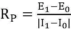
According to the formula
Calculating to obtain polarization resistance, wherein R
PIs a polarization resistance, I
1For the metal to be measured at polarization potential E
1A lower generated polarization current;
according to the formula
Calculating to obtain corrosion current, wherein I
corrFor corrosion current, I
2For the metal to be measured at polarization potential E
2Polarization current generated at the bottom, I
3For the metal to be measured at polarization potential E
3Polarization current generated at the bottom, I
4For the metal to be measured at polarization potential E
4Polarization current generated at the bottom, I
5For the metal to be measured at polarization potential E
5A lower generated polarization current;
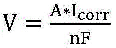
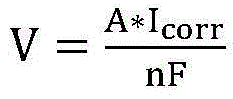
according to the formula
And calculating to obtain the corrosion rate, wherein V is the corrosion rate, A is the atomic mass of the metal, n is the ion valence number of the metal, and F is the Faraday constant.
Compared with the prior art, the invention has the beneficial effects that: the conductive pen point is small and portable, does not need an external circuit and electrolyte, only needs to be aligned with a part to be tested to measure, and can be used for corrosion tests of small areas of steel structures and various metal surfaces, particularly for parts which are difficult to enter by large instruments; the liquid absorption gasket is internally provided with electrolyte, has excellent water retention and conductivity, and ensures the normal work of the quick corrosion measuring pen.
Detailed Description
In order to make the objects, technical solutions and advantages of the embodiments of the present invention clearer, the technical solutions in the embodiments of the present invention will be clearly and completely described below with reference to the drawings in the embodiments of the present invention, and it is obvious that the described embodiments are some, but not all, embodiments of the present invention. The components of embodiments of the present invention generally described and illustrated in the figures herein may be arranged and designed in a wide variety of different configurations.
Thus, the following detailed description of the embodiments of the present invention, presented in the figures, is not intended to limit the scope of the invention, as claimed, but is merely representative of selected embodiments of the invention. All other embodiments, which can be derived by a person skilled in the art from the embodiments given herein without making any creative effort, shall fall within the protection scope of the present invention.
It should be noted that: like reference numbers and letters refer to like items in the following figures, and thus, once an item is defined in one figure, it need not be further defined and explained in subsequent figures. Meanwhile, in the description of the present invention, the terms "first", "second", and the like are used only for distinguishing the description, and are not to be construed as indicating or implying relative importance.
It is noted that, herein, relational terms such as first and second, and the like may be used solely to distinguish one entity or action from another entity or action without necessarily requiring or implying any actual such relationship or order between such entities or actions. Also, the terms "comprises," "comprising," or any other variation thereof, are intended to cover a non-exclusive inclusion, such that a process, method, article, or apparatus that comprises a list of elements does not include only those elements but may include other elements not expressly listed or inherent to such process, method, article, or apparatus. Without further limitation, an element defined by the phrase "comprising an … …" does not exclude the presence of other identical elements in a process, method, article, or apparatus that comprises the element.
In the description of the present invention, it should be noted that the terms "upper", "lower", "inside", "outside", and the like indicate orientations or positional relationships based on the orientations or positional relationships shown in the drawings or orientations or positional relationships conventionally put in use of products of the present invention, and are only for convenience of description and simplification of description, but do not indicate or imply that the devices or elements referred to must have specific orientations, be constructed in specific orientations, and be operated, and thus, should not be construed as limiting the present invention.
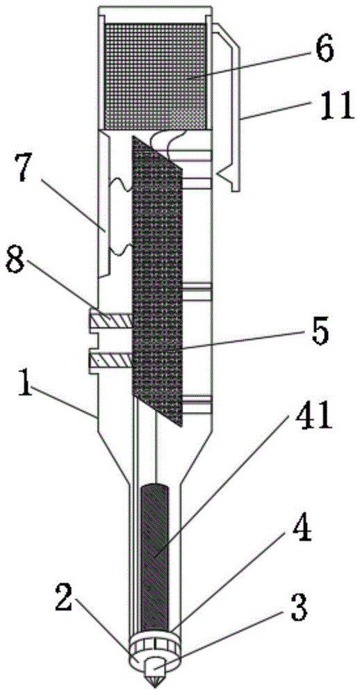
Referring to fig. 1 to 4, fig. 1 is a schematic structural diagram of a rapid corrosion measuring pen according to the present invention, fig. 2 is an arrangement diagram of electrode tips of the rapid corrosion measuring pen according to the present invention, fig. 3 is a schematic diagram of an extended state of a conductive nib in the rapid corrosion measuring pen according to the present invention, and fig. 4 is a schematic diagram of a retracted state of the conductive nib in the rapid corrosion measuring pen according to the present invention. A rapid corrosion measuring pen comprises a pen container 1, a liquid absorption gasket 2, a conductive pen point 3, an electrode tip 4 and a circuit board 5, wherein one end of the pen container 1 is open; the liquid absorption gasket 2 is arranged at the opening end of the pen container 1, and electrolyte is absorbed in the liquid absorption gasket 2; the conductive pen point 3 is telescopically arranged on the liquid absorption gasket 2 and has a contraction state and an extension state, when in the contraction state, the conductive pen point 3 is positioned in the liquid absorption gasket 2 and is electrically connected with the liquid absorption gasket 2, and when in the extension state, the conductive pen point 3 is positioned outside the liquid absorption gasket 2; the electrode tip 4 is arranged in the pen container 1, one end of the electrode tip is contacted with the liquid absorption gasket 2, and the electrode tip 4 comprises a reference electrode 41, a first insulating layer 42 and an auxiliary electrode 43 which are sequentially arranged from inside to outside; the circuit board 5 is arranged in the pen container 1 and is electrically connected with the conductive pen point 3, the reference electrode 41 and the auxiliary electrode 43 respectively.
When the rapid corrosion measuring pen is practically used, the conductive pen point 3 is used as a conductor, the conductive pen point 3 is contacted with external metal to be measured, so that the conductive pen point 3 is contracted to a contraction state, the conductive pen point 3 is fully contacted with the metal to be measured and is electrically connected with the liquid absorption gasket 2, meanwhile, the liquid absorption gasket 2 is contacted with the metal to be measured, further, the metal to be measured serves as a working electrode, the liquid absorption gasket 2 contains electrolyte and can serve as a conductive medium, and the auxiliary electrode 43, the reference electrode 41 and the working electrode are conducted. The circuit board 5 receives the electric signals from the electrodes, and the corrosion potential, the corrosion current and the corrosion rate of the metal to be measured can be obtained through internal signal processing and analysis, after the measurement is completed, the conductive pen point 3 is separated from the metal to be measured, and the conductive pen point 3 extends to the extending state.
The pen container 1 is designed to be a gel pen shape, and the size of the pen container can be designed to be less than or equal to phi 30mm x 120mm, so that the pen container is convenient to carry.
In one embodiment, the conductive nib 3 comprises a conductive contact head 31, a second insulating layer 32 and an elastic member 33 which are connected in sequence, one end of the liquid suction gasket 2 facing the outside of the pen container 1 is provided with a mounting groove 21 for accommodating the conductive contact head 31, one end of the elastic member 33 far away from the second insulating layer 32 is connected with the bottom of the mounting groove 21, and when the elastic member 33 contracts, the conductive contact head 31 is positioned in the mounting groove 21 and is electrically connected with the liquid suction gasket 2. By externally pressing the conductive contact 31, the conductive contact 31 is inserted into the mounting groove 21 against the elastic force of the elastic member 33, and the conductive contact 31 is brought into contact with the groove wall of the mounting groove 21, thereby electrically connecting the conductive contact 31 with the liquid-absorbing pad 2. When the external pressure is removed, the conductive contact head 31 is pushed out of the mounting groove 21 by the elastic force of the elastic member 33, and the conductive contact head 31 is separated from the contact with the liquid absorbing pad 2. Preferably, the elastic member 33 is a spring. The conductive contacts 31 may be made of a material having good electrical conductivity, such as copper for the conductive contacts 31.
In one embodiment, the absorbent pad 2 is a water absorbent sponge and the electrolyte is a KCl solution. The water absorption sponge has high water absorption, and KCl solution is contained in the water absorption sponge, so that the reference electrode 41 and the auxiliary electrode 43 are conducted with the metal to be tested, the resistance of a test system is reduced, and the accuracy of test data is ensured.
In one embodiment, the rapid corrosion measuring pen further comprises a rechargeable battery 6, and the rechargeable battery 6 is connected with the circuit board 5 and used for supplying power to the circuit board 5. In the measuring process of the rapid corrosion measuring pen, power needs to be supplied to the circuit board 5, so that the circuit board 5 can apply polarization potential to metal to be measured through the conductive pen point 3, and considering that some engineering sites cannot supply power, the rechargeable battery 6 is arranged in the pen container 1, the rechargeable battery 6 can be charged, and meanwhile, the circuit board 5 can be supplied with power for a long time. In one embodiment, a cap is detachably mounted on the end of the pen container 1 away from the opening to facilitate charging the rechargeable battery 6.
In one embodiment, the circuit board 5 is connected with a display screen 7, and the display screen 7 is arranged on the pen container 1 in a penetrating mode. The circuit board 5 sends the obtained measurement data to the display screen 7 for display, so that a measurer can conveniently observe the measurement data, such as the corrosion potential, the corrosion current and the corrosion rate of the metal to be measured.
In one embodiment, the circuit board 5 includes a current amplifier, an A/D converter and a microprocessor connected in series. The current amplifier can receive the micro current from the electrode, amplify the received micro current and transmit the amplified micro current to the A/D converter, the A/D converter is used for converting the current into a digital signal and transmitting the digital signal to the microprocessor, and the microprocessor analyzes and processes the digital signal to obtain the corrosion potential, the corrosion current and the corrosion rate of the metal to be detected.
In one embodiment, the reference electrode 41 and the auxiliary electrode 43 are both circular rings in cross section, the reference electrode 41 is an Ag/AgCl gel electrolyte reference electrode 41, and the outer surface of the reference electrode 41 is covered with a dense AgCl film layer. This setting can realize the mobility of the inside electrolyte of reference electrode 41, water-retaining property, guarantees the accuracy of reference electrode 41, and reference electrode 41 and auxiliary electrode 43 all design for the ring form simultaneously, guarantee reference electrode 41, auxiliary electrode 43 and imbibition gasket 2 full contact to the inside return circuit when guaranteeing the test switches on. Furthermore, the reference electrode 41 has an outer casing made of polytetrafluoroethylene, the inner gel electrolyte adopts polyacrylamide and saturated KCl solution, and one end of the outer casing is provided with microporous ceramic.
In one embodiment, the circuit board 5 is provided with two buttons 8, and the two buttons 8 are arranged on the pen container 1 in a penetrating manner. The measuring mode of the circuit board 5 can be changed through the buttons 8, such as a potential test or a corrosion rate test, and the two buttons 8 correspond to the potential test and the corrosion rate test respectively.
Referring to fig. 5, fig. 5 is a schematic diagram of a pen cap of the rapid erosion measurement pen according to the present invention. In one embodiment, a suspension bracket 11 is arranged at one end of the pen container 1 far away from the opening, and/or a pen cap 9 is sleeved at the opening end of the pen container 1. The pen container 1 can be suspended and carried through the suspension bracket 11, so that a measurer can conveniently carry the quick corrosion measuring pen. The pen cap 9 is sleeved on the pen container 1 and can protect the conductive pen point 3.
A test method adopting the rapid corrosion measuring pen comprises the following steps:
s1, contacting the conductive pen point 3 with the metal to be detected, so that the conductive pen point 3 is in a contraction state, and the metal to be detected is contacted with the liquid absorption gasket 2;
s2, measuring the initial corrosion potential E of the metal to be measured0And initial corrosion current I0;
S3, sequentially applying a plurality of polarization potentials to the metal to be detected to obtain the polarization current generated by the metal to be detected under each polarization potential, wherein the plurality of polarization potentials comprise E1、E2、E3、E4And E5;
S4, according to the formula
Calculating to obtain polarization resistance, wherein R
PIs a polarization resistance, I
1For the metal to be measured at polarization potential E
1A lower generated polarization current;
s5, according to the formula
Calculating to obtain corrosion current, wherein I
corrFor corrosion current, I
2For the metal to be measured at polarization potential E
2Polarization current generated at the bottom, I
3For the metal to be measured at polarization potential E
3Polarization current generated at the bottom, I
4For the metal to be measured at polarization potential E
4Polarization current generated at the bottom, I
5For the metal to be measured at polarization potential E
5A lower generated polarization current;
s6, according to the formula
And calculating to obtain the corrosion rate, wherein V is the corrosion rate, A is the atomic mass of the metal, n is the ion valence number of the metal, and F is the Faraday constant.
In the step S1, when the rapid corrosion measuring pen of the present invention is actually used, the conductive pen tip 3 is used as a conductor, and the conductive pen tip 3 is contacted with an external metal to be measured, so that the conductive pen tip 3 contracts to a contracted state, the conductive pen tip 3 is fully contacted with the metal to be measured and is electrically connected to the liquid absorption pad 2, and the liquid absorption pad 2 is contacted with the metal to be measured, so that the metal to be measured serves as a working electrode, the liquid absorption pad 2 contains an electrolyte, and can serve as a conductive medium, so as to conduct the auxiliary electrode 43, the reference electrode 41, and the working electrode.
In the above step S2, before the corrosion rate is measured, it is necessary to perform potential measurement, that is, to measure the corrosion potential E of the metal to be measured0And corrosion current I0. When the potential measurement is carried out, the circuit board 5 receives the electric signal from the electrode, converts the electric signal into a digital signal to be output through internal signal processing and analysis, and then obtains the corrosion potential E of the metal to be measured0And corrosion current I0。
In the above step S3, since 5 pieces of feedback current data are required for measuring the etching rate, the circuit board 5 is based on the etching potential E0Actively applying 5 polarization potentials to the metal to be tested, wherein the 5 polarization potentials are respectively E1、E2、E3、E4And E5In which E1=E0+10mV,E2=E0+120mV,E3=E0+130mV,E4=E0-120mV,E5=E0130mV to obtain 5 polarization currents generated by the metal to be detected under 5 polarization potentials respectively, wherein the 5 polarization currents are I1、I2、I3、I4And I5。
In the above step S4, the polarization resistance R in the corrosion rate calculation
PIs approximated by a linear slope of the applied potential relative to the corrosion potential +10mV and the current data fed back, and is thus approximated by a formula
Calculating to obtain polarization resistance R
P。
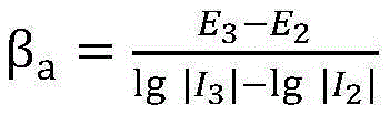
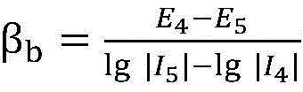
In the above step S5, the slope calculation method of the Tafel region anodic polarization curve in the corrosion rate calculation is calculated using the linear slopes of the applied potentials +120mV, +130mV relative to the corrosion potentials and the feedback current data, and thus the anodic polarization is calculatedSlope of the curve beta
aBy the formula
Calculating to obtain; the calculation method of the cathode polarization curve slope of the Tafel region in the corrosion rate calculation is calculated by utilizing the linear slopes of the applied potential and the feedback current data relative to the corrosion potential of-120 mV and-130 mV, so that the cathode polarization curve slope beta
bBy the formula
Calculated, and then the corrosion rate calculation formula is utilized
Polarization resistance R
PSlope beta of anodic polarization curve
aAnd cathode polarization curve slope beta
bSubstituting into the corrosion rate calculation formula to obtain
Thereby calculating corrosion current I
corr。
In the above step S6, the corrosion current I is obtained based on the calculation
corrThen according to the formula of corrosion rate
The corrosion rate V can be calculated. The testing method obtains the polarization resistance R by acquiring the linear slope at two points
P. And then the polarization curve slope beta of Tafel region
a、β
bThe corrosion rate of the metal to be detected can be calculated by recording the magnitude of current fed back by applying a certain potential to the metal to be detected, and the calculation is convenient and fast, time-saving and efficient, and has good applicability.
Compared with the prior art, the invention has the beneficial effects that: the portable corrosion tester is small and portable, does not need an external circuit and electrolyte, only needs to align the conductive pen point 3 to a part to be tested for measurement, and can be used for corrosion testing of small areas of steel structures and various metal surfaces, particularly for parts which are difficult to enter by large-scale instruments; the liquid absorption gasket 2 contains electrolyte, has excellent water retention and conductivity, and ensures the normal work of the quick corrosion measuring pen.
The above description is only a preferred embodiment of the present invention, and is not intended to limit the present invention in any way, so that any simple modification, equivalent change and modification made to the above embodiment according to the technical spirit of the present invention will still fall within the scope of the technical solution of the present invention without departing from the content of the technical solution of the present invention.