Disclosure of Invention
Aiming at the defects and shortcomings in the prior art, the invention provides a modularized heat pump unit, which comprises a heat pump box body, wherein the heat pump box body is provided with a height in a first direction vertical to the ground, a width in a second direction vertical to the first direction and a thickness in a third direction vertical to the first direction and the second direction; a plurality of installation positions of the single heat pump modules are arranged in the heat pump box body, one single heat pump module can be installed on each installation position, and the plurality of single heat pump modules are arranged along the second direction; the heat pump box body is a box body with standardized size, and the single heat pump module is provided with a compressor, a shell and tube heat exchanger, a fin heat exchanger, a fan and a waterway circulation system; the fins of the fin heat exchanger extend along a first direction, and the fan is arranged on one side of the fin heat exchanger along a third direction, so that air flows through the fin heat exchanger from the opening on one side of the heat pump box body along the third direction and flows to the opening on the other side of the heat pump box body;
the waterway circulation systems of the single heat pump modules are provided with water pipes and interface parts which are easy to disassemble, and when a plurality of single heat pump modules are arranged side by side along a second direction, the waterway circulation systems of the single heat pump modules are mutually connected through the interface parts to form a continuous waterway;
the number of the single heat pump modules is 2 or more than 2, and each single heat pump module has the same structure and size.
Further, the number of the single heat pump modules is 3 to 6.
Furthermore, the heat pump box body comprises a top plate, a ground plate, a side wall plate and an end wall plate, wherein an opening is formed in the side wall plate, and the opening corresponds to the air inlet and the air outlet of the fin heat exchanger of the single heat pump module.
Further, the heat pump case has a connection structure facilitating the successive stacking thereof in the first direction.
Further, the opening part on the lateral wall board of heat pump box is provided with the blast gate, the angle of blast gate can be adjusted, and the blade angle of the blast gate of air outlet department upwards to upwards reflect the noise of fan.
Further, the compressor and the fan are arranged on one side, the fan is arranged in the noise reduction box, and the compressor is arranged in the sound-proof housing.
Furthermore, an inlet air quantity distributor is arranged in front of the fin heat exchanger, and the inlet air quantity distributor enables air to uniformly flow through fins of the fin heat exchanger.
Furthermore, the heat pump box body is provided with an incoming line control box, and the control box is connected with each single heat pump module and controls the single heat pump modules.
The invention also provides a modular heat pump unit system, which is formed by stacking the units in a first direction perpendicular to the ground.
Further, the system is stacked with 3-6 layers.
The invention can realize the following technical effects:
(1) the heat pump unit is conveniently stacked by setting the box body of the heat pump unit to be in a standardized size, so that the occupied area of the land is greatly reduced. A plurality of single heat pump modules can be placed in the box body of the heat pump unit according to requirements, and the number of the modules is flexibly set, so that the heat pump units with different output powers can be matched and any combination can be realized.
(2) Each single heat pump module is arranged at the side of the air flow path and at the side of the air flow path, so that the cold island effect cannot be generated, and the heat pump units cannot influence each other after being stacked.
(3) The pipelines of the waterway circulation systems of all the single heat pump modules are prefabricated in advance and do not need to be installed on site, and the modules are quickly combined into a complete pipeline system through the waterway interfaces which are easy to disassemble, so that accumulated errors can be automatically eliminated, and the time cost of site construction is greatly reduced.
(4) Through the noise reduction processing to monomer heat pump module, the influence of the noise that can greatly reduced unit to near resident.
(5) The water pan and the auxiliary defrosting system in the unit can thoroughly solve the problem of secondary freezing of defrosting water, and the safety and the heat exchange efficiency are improved.
(6) The flow equalizing plate can evenly distribute air to the heat exchange area of the fin heat exchanger, and the heat exchange efficiency of the system is improved.
Drawings
In order to more clearly illustrate the technical solutions in the embodiments of the present invention, the drawings that are needed in the embodiments or the prior art descriptions will be briefly described below.
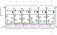
Fig. 1 is a schematic back view of a modular heat pump unit provided in the present invention.
Fig. 2 is a schematic front view of a modular heat pump unit according to the present invention.
Fig. 3 is a schematic perspective view of a modular heat pump unit provided in the present invention.
Fig. 4 is a schematic top view of a modular heat pump unit according to the present invention.
Fig. 5 is a schematic side view of a modular heat pump unit according to the present invention.
Fig. 6 is a schematic perspective view of a single heat pump module of a modular heat pump unit according to the present invention.
Fig. 7 is a schematic side view of a single heat pump module of a modular heat pump unit according to the present invention.
Fig. 8 is a schematic top view of a single heat pump module of a modular heat pump unit according to the present invention.
Fig. 9 is a perspective view of a single heat pump module of the modular heat pump unit provided with the sound-absorbing panel according to the present invention.
Fig. 10(a) is a schematic side view of a single heat pump module of the modular heat pump unit provided with the sound-absorbing panel according to the present invention.
Fig. 10(b) is a schematic front view of a single heat pump module of the modular heat pump unit provided with the sound-absorbing panel according to the present invention.
Fig. 11(a) is a schematic front view of the sound-absorbing panel in the present invention.
Fig. 11(b) is a schematic side view of the sound-absorbing panel of the present invention.
Fig. 11(c) is a schematic plan view of the sound-absorbing panel of the present invention.
Fig. 12(a) is a schematic view of a noise reduction case in the present invention.
Fig. 12(b) is a sectional view taken along line a-a of fig. 12 (a).
Fig. 12(c) is an enlarged view of a portion a of fig. 12 (b).
Fig. 12(d) is an enlarged view of a portion B of fig. 12 (B).
Fig. 13 is a perspective view of a noise-reduction case of the present invention.
Fig. 14 is a schematic view of a noise propagation path.
Fig. 15 is a front view of a water pipe (single pipe) and a clamp structure of the heat pump unit of the present invention.
Fig. 16 is a plan view of fig. 15 (the clip structure is omitted).
Fig. 17 is a left side view of fig. 15 (with the clip structure omitted).
Fig. 18 is a front view of two water pipes connected together.
Fig. 19 is a sectional view a-a of fig. 18.
Fig. 20 is an enlarged view of a portion B of fig. 19.
Fig. 21(a) is a front view schematically showing a clip structure.
Fig. 21(b) is a sectional view taken along line a-a of fig. 21 (a).
Fig. 22(a) is a schematic front view of a mechanical tee assembly.
Fig. 22(b) is a sectional view taken along line a-a of fig. 22 (a).
Fig. 22(c) is a sectional view taken along line B-B of fig. 22 (a).
Figure 23 is a perspective view of a mechanical tee assembly.
FIG. 24 is a schematic structural view of the mechanical tee assembly after connection with a heat pump unit shell-tube connection.
Fig. 25 is an enlarged view of a portion C of fig. 24.
FIG. 26 is a schematic top view of a heat pump unit equipped with flow equalization plates.
Fig. 27(a) is a schematic front view of a flow equalizing plate.
Fig. 27(b) is a left side view of fig. 27 (a).
Fig. 27(c) is a plan view of fig. 27 (a).
Fig. 28 is a perspective view of a heat pump unit equipped with a flow equalizing plate.
FIG. 29 is a side view of a heat pump unit with a water tray.
Fig. 30(a) is a front view of the drip tray.
FIG. 30(b) is a sectional view taken along line A-A in FIG. 30 (a).
Fig. 30(c) is a left side view of fig. 30 (a).
Fig. 30(d) is a plan view of fig. 30 (a).
1-heat pump box body, 2-single heat pump module, 3-one-way inlet wire control box, 4-inlet air valve, 5-outlet air valve, 6-access door, 7-water pipe component, 8-defrosting water collecting header pipe, 9-compressor, 10-fan, 11-shell and tube heat exchanger, 12-fin heat exchanger, 201-acoustic board, 202-frame bounding wall, 203-reinforcing rib, 21-guide plate, 22-perforated plate, 23-superfine fiber acoustic material, 901-noise reduction box body, 91-inner plate, 92-panel, 93-acoustic material, 94-top plate component, 95-side plate component, 96-bottom plate component, 71-water pipe, 72-hoop structure, 73-mechanical three-way component, 74 heat pump unit shell and tube connecting pipe, 71-1 groove, 72-5 boss, 72-6 tip protrusion, 72-1 semi-ring, 72-2 lug, 72-3 bolt, 72-4 rubber sealing ring, 3-1 rubber sealing gasket, 33 flow equalizing plate, 33-1 transverse clapboard, 33-2 vertical clapboard, 44-1 protective plate, 44-2 surrounding groove, 44-3 inclined plane, 44-4 drain pipe, 44-5 conical structure, 44-6 insulating layer and 44-7 electric heating band
Detailed Description
The invention will now be described in further detail with reference to the accompanying drawings, which are provided solely for a better understanding of the invention and are not to be construed as limiting the invention. All other embodiments, which can be derived by a person skilled in the art from the patented embodiments of the invention without any inventive step, are within the scope of protection of the invention.
In the description of the present invention, it should be noted that, as the terms "center", "upper", "lower", "left", "right", "vertical", "horizontal", "inner", "outer", etc. appear, their indicated orientations or positional relationships are based on those shown in the drawings, and are only for convenience of description and simplicity of description, but do not indicate or imply that the referred device or element must have a specific orientation, be constructed in a specific orientation, and be operated, and thus, should not be construed as limiting the present invention. Furthermore, the terms "first" and "second," if any, are used for descriptive purposes only and are not to be construed as indicating or implying relative importance.
In the description of the present invention, it should be noted that, unless otherwise explicitly stated or limited, the terms "mounted," "connected," and "connected" should be interpreted broadly, e.g., as being fixed or detachable or integrally connected; they may be connected directly or indirectly through intervening media, or they may be interconnected between two elements. The specific meanings of the above terms in the present invention can be understood in specific cases to those skilled in the art.
Example 1
Fig. 1 to 4 show a modular heat pump unit comprising a heat pump housing 1, said heat pump housing 1 having a height in a first direction perpendicular to the ground, a width in a second direction perpendicular to said first direction and a thickness in a third direction perpendicular to both said first and second directions; a plurality of installation positions of the single heat pump modules 2 are arranged in the heat pump box body, one single heat pump module 2 can be installed on each installation position, and the plurality of single heat pump modules 2 are arranged along the second direction; the heat pump enclosure 1 is a standardized size enclosure, for example the heat pump enclosure 1 may be sized to conform to an international shipping container. The heat pump tank 1 is capable of stacking a plurality of heat pump tanks because of its standardized size, and has a connection structure on each heat pump tank so that it is continuously stacked in the first direction.
Fig. 5 to 8 show a single heat pump module 2 provided in the modular heat pump unit, where the single heat pump module 2 has a compressor 9, a shell and tube heat exchanger 11, a fin heat exchanger 12, a fan 10, and a water circuit system. Wherein the fins of the fin heat exchanger 12 extend along the first direction, and the fan 10 is disposed on one side of the fin heat exchanger 12 along the third direction, so that the air flows through the fin heat exchanger 12 from the opening on one side of the heat pump box 1 and flows to the opening on the other side of the heat pump box 1 along the third direction. The reason why the fins of the fin heat exchanger 12 extend in the first direction is to smoothly discharge the defrosting water under the action of gravity, so as to prevent the defrosting water from freezing again and adversely affecting the unit.
The water path circulating system of the single heat pump modules 2 is provided with a water pipe part 7 and an interface part which is easy to disassemble, and when the single heat pump modules 2 are arranged side by side along the second direction, the water path circulating systems of the single heat pump modules 2 are connected with each other through the interface part and form a continuous water path.
The number of the single heat pump modules is 2 or more than 2, and in an optimized embodiment, the number of the single heat pump modules is 3-6. And each of the unit heat pump modules has the same structure and size. It will be appreciated that the number of individual heat pump modules may be increased according to the actual need, for example to 8, 10 or more. The above quantities are merely illustrative and do not limit the scope of the claims.
Specifically, the heat pump box 1 comprises a top plate, a ground plate, a side wall plate and an end wall plate, wherein an opening is formed in the side wall plate, and corresponds to an air inlet and an air outlet of the fin heat exchanger 12 of the single heat pump module 2. An inlet air valve 4 and an outlet air valve 5 are arranged on the opening. In other embodiments a venetian blind may be used instead of the air valve. In the optimized embodiment, the angle of the blades on the air valve can be adjusted, which is significant for reducing noise, for example, when the angle of the blades of the outlet air valve 5 is adjusted to be inclined upwards, the noise generated by the fan is reflected upwards to a space above 2 meters by the blades of the outlet air valve, while the space for people to move is generally below 2 meters, so the influence of the noise generated by the fan is greatly reduced.
In order to further reduce the influence of noise, the compressor and the fan are disposed at one side of the single heat pump module 2, and the fan is disposed in the noise reduction case, and the compressor is disposed in the soundproof cover so as to reduce noise generated from the two noise components.
In a specific embodiment, an inlet air quantity distributor is arranged in front of the fin heat exchanger, and the inlet air quantity distributor enables air to uniformly flow through fins of the fin heat exchanger.
Be provided with inlet wire control box 3 all the way on the heat pump box, inlet wire control box 3 and every all the way monomer heat pump module is connected, and right monomer heat pump module controls, so can realize controlling all monomer heat pump modules through a control box to reduce the complexity and the cost of circuit, and be favorable to all monomer heat pump modules to carry out cooperative control.
The structure and operation of the water pipe 7 and the detachable joint member according to the present invention will be explained with reference to fig. 15 to 25. The water pipe part 7 in the invention has the characteristics of quick connection and automatic error elimination. Specifically, the water pipe member 7 includes a water pipe 71 and a clamp structure 72 for connecting two adjacent water pipes, and the clamp structure 72 is the quick detachable connector member. The end of the water pipe 71 is provided with a groove 71-1, the clamp structure 72 is provided with two half rings 72-1, and the two ends of the half rings 72-1 are provided with lugs 72-2; the two sides of the half ring 72-1 are provided with bosses 72-5 which are raised along the circumferential direction, an internal groove is formed between the bosses 72-5, and a rubber sealing ring 72-4 is arranged in the groove.
Figure 18 shows a block diagram of two water lines 71 connected by a clip structure 72. The two water pipes 71 are connected in an end-to-end manner, bosses 72-5 of two half rings 72-1 of the hoop structure 72 respectively extend into grooves 71-1 at the end parts of the water pipes at two sides, the two half rings are fixed through a connecting piece, and the two half rings form a circular ring and realize the connection of the water pipes at two sides. In a particular embodiment, the connector may be a bolt 2-3.
As shown in FIG. 20, the rubber packing 72-4 has tip protrusions 72-6 extending in the circumferential direction on both sides thereof, which abut against the edges of the groove 71-1 at the end of the water pipe. Since the rubber packing 72-4 has elasticity, it is possible to form a good seal to the water pipe connection and to eliminate errors in size and assembly when the water pipe is connected.
Specifically, a mechanical three-way assembly 73 is further arranged on the water pipe 71, and the mechanical three-way assembly 73 is used for being connected with a heat pump unit shell pipe connecting pipe 74. Fig. 22-25 show the specific structure and assembly relationship of the mechanical three-way component 3, wherein a rubber gasket 73-1 is arranged at the joint of the mechanical three-way component 73 and the water pipe 71, so as to seal the water pipe 71 and the mechanical three-way component 73. Specifically, as shown in fig. 25, the diameter of the circular tube of the mechanical three-way component 3 is a, the hole diameter of the water pipe 1 matched with the circular tube is slightly larger than a, a gap of 1-2 mm is formed between the circular tube and the water pipe for adjusting the error, and the gap is sealed by the rubber sealing gasket 3-1 inside to prevent water leakage.
It is understood that the water pipe 1 may be a straight pipe or a bent pipe, and may be connected and fixed by a clamp structure as long as the both ends have grooves.
Through the clamp structure with water piping connection, the rubber circle in the clamp structure has certain elasticity and clearance, can compensate various errors in water pipe processing and the assembling process, greatly reduced the production degree of difficulty and to workman operation horizontally requirement, and can realize the quick installation between the water pipe, be applicable to various heat pump set's on-the-spot water route assembling process very much.
The noise reduction structure of the heat pump unit of the present invention will be specifically explained with reference to fig. 8 to fig. 14.
As shown in fig. 8, 9 and 10, a fan silencer is arranged downstream of a fan 10 of the heat pump unit in an airflow direction, the fan silencer includes a frame enclosing plate 202 and a plurality of sound-absorbing plates 201, the frame enclosing plate 202 is arranged around the fan 10, and the sound-absorbing plates 201 are arranged on the frame enclosing plate 202 at intervals.
Fig. 11 shows a specific structure of the sound-absorbing panel. The sound-absorbing plate 201 is composed of a guide plate 21 and a porous plate 22, and the sound-absorbing plate 201 extends along the airflow direction so that the airflow passes through the guide plate 21 and then passes through the porous plate 22.
The sound-absorbing board is also provided with a superfine fiber sound-absorbing material 23. In a specific embodiment, the ultra-fine fiber sound-absorbing material 23 is a strip shape extending from one side of the sound-absorbing plate to the other side, and in a preferred embodiment, the number of the ultra-fine fiber sound-absorbing material 23 is two or more. The sound-absorbing boards 201 are arranged on the frame enclosing plate at intervals of the same interval L. The distance L can be flexibly adjusted according to requirements. Specifically, the guide plate 21 is provided with a plurality of guide protrusions. The frame enclosing plate is provided with a reinforcing rib 203, and the reinforcing rib 203 is used for reinforcing and fixing the frame enclosing plate 202.
As shown in fig. 9, the sound-absorbing panel 201 has a height in a direction perpendicular to the airflow direction, which corresponds to the height of the air outlet.
The fan is a main noise source of the air source heat pump unit, and therefore, the noise reduction for the fan is one of the main targets. The working principle of the fan silencer provided by the invention is as follows: when the fan rotates, air (containing noise) is flushed onto the porous plate through the guide plate, part of the air is absorbed by the sound absorption material inside, and part of the air is reflected to the sound absorption plate beside the fan, so that the noise is gradually attenuated repeatedly, and the decibel value of the noise is greatly reduced when the noise is transmitted to the outer surface of the silencer along with the air. Fig. 14 shows the noise propagation and attenuation process.
The compressor is another major source of noise in the heat pump unit, and therefore it is also important to control the noise of the compressor. As shown in fig. 12 and 13, the compressor of the heat pump unit disclosed in the present invention is disposed in a noise reduction box 901, the noise reduction box 901 includes a top plate assembly 94, a side plate assembly 95 and a bottom plate assembly 96, wherein the side plate assembly 95 includes an inner plate 91 and a face plate 92, and a sound insulation material is disposed between the inner plate 91 and the face plate 92.
The top plate assembly 94 and bottom plate assembly 96 are provided with slots into which the side plates may be inserted and form a labyrinth seal, as shown in fig. 12c and 12 d.
The noise reduction principle of the compressor in the embodiment mainly comprises two ways of absorption and barrier propagation. The compressor is wrapped in by the noise reduction box body, and when the compressor works, mechanical friction, periodic meshing of the movable scroll and the static scroll and electromagnetic sound of the motor are mixed together to form a complex noise frequency spectrum. The noise is transmitted from the compressor, part of the noise is absorbed by the soundproof cotton through the through holes on the inner plate, part of the noise is blocked by the panel, the transmission part of the noise is transmitted to the air, and the noise is greatly attenuated through the multilayer treatment, and the transmission path is shown in fig. 14. In addition, the clamping grooves of the bottom plate and the top plate form a labyrinth seal, so that noise leakage can be reduced.
Furthermore, an electric cabinet is arranged on the heat pump unit and is positioned right in front of the compressor, so that noise transmission of the compressor can be further prevented.
In this embodiment, the compressor and the fan are disposed on the same side of the heat pump unit.
The heat pump unit is characterized in that sound absorption materials are further arranged on the inner wall of the box body of the heat pump unit, so that noise of the heat pump unit is further reduced.
The following explains the specific structure and operation principle of the air quantity distributor of the present invention with reference to fig. 26 to 28. The air quantity uniform distributor in the invention is specifically a flow equalizing plate 33. Two areas with triangular sections on a plane parallel to the ground are formed between the fin heat exchanger 2 and the heat pump box body 1, and a flow equalizing plate 33 is arranged in the triangular areas.
The flow equalizing plate 33 is provided with a plurality of transverse partition plates 33-1 and vertical partition plates 33-2, and a plurality of air ducts 33-3 are partitioned between the transverse partition plates 33-1 and the vertical partition plates 33-2. Specifically, the cross section of the flow equalizing plate on a plane parallel to the ground is triangular or approximately triangular, and the surface where the inclined edge c of the triangle is located is aligned with the surface of one side of the fin heat exchanger facing the air inlet. And air is uniformly distributed on the surface of the fin heat exchanger under the action of the flow equalizing plate.
It can be seen from the figure that the plurality of transverse partition plates 33-1 on the flow equalizing plate are parallel to each other, and the plurality of vertical partition plates 33-2 are also parallel to each other.
Specifically, the flow equalizing plate is a plastic or PVC component. It is understood that the flow equalizing plate can be made of other suitable materials, such as sheet metal, and can be flexibly selected by those skilled in the art according to the actual requirements, and the foregoing selection of the materials is only an example and does not limit the scope of the present invention.
Specifically, the cross section of the flow equalizing plate is a right-angled triangle. It will be appreciated that the cross-sectional shape may also be approximately that of a right triangle.
Under the action of the flow equalizing plate 33, air entering from an air inlet of the heat pump unit can be uniformly distributed to the surface of the fin heat exchanger, so that the heat exchange capacity of the fin heat exchanger can be exerted to the maximum extent, and the heat exchange efficiency is improved.
The structure and the working principle of the water pan and the auxiliary defrosting device according to the present invention will be explained with reference to fig. 29 to 30.
The heat pump unit of the invention is also provided with a water pan 44, and the water pan 44 is positioned at the lower part of the fin heat exchanger 12 and extends along a third direction.
The fins of the finned heat exchanger 12 extend in a first direction, and the ends of the fins extend into the water collector 44.
The water pan 44 has a guard plate 44-1 and a surrounding groove 44-2, which surround the end of the fin and form a closed cavity. Specifically, as shown in fig. 30(b), the protective plate 44-1 is fixed on the side surface of the surrounding groove 44-2 of the water pan, the protective plate 44-1 extends upwards and inclines towards the fins, and when the fins penetrate into the water pan, the protective plate 44-1 can be lapped on the side surface of the fins, so that the water pan forms a closed cavity wrapping the fins, that is, defrosting water falls into the water pan conveniently and heat loss is prevented.
The frost formed on the fins forms water after defrosting and flows downwards into the cavity formed by the water pan along the fins.
The bottom of the water pan is provided with an inclined plane 44-3 and a drain pipe 44-4 thereof, the inlet of the drain pipe 44-4 is positioned at or close to the lowest part of the inclined plane, and the defrosted water on the fins is collected to the lowest part along the inclined plane after entering the water pan and is discharged from the drain pipe. As shown in fig. 30(a), the inclined surface forms an included angle α with the horizontal plane, and the included angle α may be set according to the requirement, for example, may be 15 ° to 60 °, and may be 30 ° to 45 ° in the optimized embodiment.
As shown in fig. 30(b) and 30(d), the bottom of the water-receiving tray is provided with a plurality of high-density conical structures 44-5 or protrusions. The conical structure 44-5 or the bulge has the function of preventing the water film from generating and further controlling the generation of water drops, and finally the purpose that the water drops are not suspended on the side surface is achieved, namely secondary icing is not performed. Therefore, when the defrosting water flows into the water receiving tray, even if a water film is formed, the water film can be punctured by the conical structure or the bulge, so that the water film is prevented from being generated.
In an optimized embodiment, the inner wall of the water pan can be sprayed with a hydrophobic material, under the action of the hydrophobic material, a water film is more difficult to attach to the surface of the water pan, and water drops easily slide off from the surface of the inner cavity of the water pan, so that the defrosting water is discharged.
The water collector material is the sheet metal component usually, because its specific heat capacity is big, heat absorption capacity is strong, therefore its surface temperature is less than ambient temperature far away in cold areas, in order to prevent that the heat of defrosting water from being absorbed by the water collector, can paste around the water collector and establish heat preservation 44-6, and the heat preservation can be heat preservation cotton or other insulation material in specific embodiment. Meanwhile, an electric heating belt 44-7 is attached to the bottom of the water receiving tray, and the electric heating belt 44-7 is close to the outside of the water receiving tray and then wraps the sponge. In an optimized embodiment, a temperature sensor is arranged in a water pan of the unit, the temperature sensor detects the temperature in a cavity of the water pan, and the electric heating belt performs automatic control according to the temperature detected by the sensor. Under extremely cold weather, the surface temperature of the water pan is ensured to be not lower than 0 ℃ by auxiliary heat supply of the electric heating belt, thereby preventing the defrosting water from being frozen again. The heat preservation can prevent that the heat of electric heating belt from being dispersed in the air fast.
When the heat pump unit starts a defrosting mode, frost on the fin heat exchanger flows into the water pan along the aluminum foil in a liquid water mode, the bottom of the water pan is provided with an inclined plane, one side of the water pan is higher than the other side of the water pan, water flow is collected to the lowest depression along the inclined plane and then discharged through the drain pipe, and water is prevented from accumulating in the water accumulation pan and being frozen secondarily. Defrosting water gets into the ponding dish with rivers or drop drippage, in order to prevent that rivers/drop splash from becoming water foam and little drop, at the fixed cone structure of a high density in the bottom of water collector, prevent that the water film from generating and then control and generate the drop, finally reach the purpose that the side does not hang the drop, do not freeze for the second time promptly. The heat preservation cotton is pasted around the water receiving tray, and simultaneously, the electric heating belt is pasted at the bottom and is next to the sponge of wrapping up outside the water receiving tray, and through the supplementary heat supply of electric heating belt under extremely cold weather, guarantee that water receiving tray surface temperature is not less than 0 ℃, the cotton effect of heat preservation can prevent that the heat of electric heating from being given off in the air fast. In addition, the two side guard plates are fixed on the side surface of the water pan, and a closed cavity is formed by the two side guard plates and the fin heat exchanger, so that heat loss is greatly reduced. The electric heating belt, the heat preservation cotton, the guard plate, the inner side hydrophobic material, the conical structure and other ways thoroughly solve the phenomenon of secondary icing of the defrosting water.
The beneficial effect that this embodiment can realize is: the heat pump unit is conveniently stacked by setting the box body of the heat pump unit to be in a standardized size, so that the occupied area of the land is greatly reduced. A plurality of single heat pump modules can be placed in the box body of the heat pump unit according to requirements, and the number of the modules is flexibly set, so that the heat pump units with different output powers can be matched and any combination can be realized. Each single heat pump module is arranged at the side of the air flow path and at the side of the air flow path, so that the cold island effect cannot be generated, and the heat pump units cannot influence each other after being stacked. The pipelines of the waterway circulation systems of the single heat pump modules are prefabricated in advance, the waterway circulation systems do not need to be installed on site, and the modules are quickly combined into a complete pipeline system through the waterway interfaces which are easy to disassemble, so that the time cost of site construction is greatly reduced. Through the noise reduction processing to monomer heat pump module, the influence of the noise that can greatly reduced unit to near resident.
Example 2
This embodiment discloses a modular heat pump unit system, which is formed by stacking the modular heat pump units disclosed in embodiment 1 in a first direction perpendicular to the ground. The number of layers stacked in the preferred embodiment is 3-6.
The above embodiments are only used for explaining the present invention, and the structure, connection mode, manufacturing process, etc. of the components may be changed, and all equivalent changes and modifications performed on the basis of the technical solution should not be excluded from the protection scope of the present invention.