Full-automatic intelligent gas heater and heating control method
Technical Field
The embodiment of the invention relates to the technical field of gas heating, in particular to a full-automatic intelligent gas heater and a heating control method.
Background
In cold winter, people usually use various heaters to warm the indoor space in order to resist severe cold, such as the fire wall, the heated brick bed and the stove in the north of China, the charcoal pan in the south of China, the fireplace in the western country and the like. With the development of society and the popularization of electric power, a warmer using electric heat as a heat source is on the market like bamboo shoots in spring after rain. Due to the continuous heat transfer rate of the traditional culture, a considerable part of people prefer and need to use combustion type heating equipment for heating in specific environments, and along with the popularization and the use of fuel gas, more and more combustion type heating equipment combustion sources select the fuel gas. The gas heating furnace has the advantages of unique heat regulation, heat transfer speed and unconstrained heat covering. However, in the existing gas heating, the heat exchange with the outside air is finally performed through the continuous heat exchange of a third-party medium, so as to realize the heating effect, and in the continuous heat exchange process, the heat loss is high, so that the energy consumption is high, and the heat utilization rate is low.
Disclosure of Invention
Therefore, the embodiment of the invention provides a full-automatic intelligent gas heater and a heating control method, and aims to solve the problems of high energy consumption and low heat energy utilization rate of gas heating in the prior art.
In order to achieve the above object, the embodiments of the present invention provide the following technical solutions:
according to a first aspect of the embodiments of the present invention, there is provided a full-automatic intelligent gas heater for indoor heating, comprising:
the waste gas heat recovery device comprises a machine body, wherein a waste gas chamber, a heat exchange chamber and a combustion chamber which are independent from each other are respectively formed in the machine body from top to bottom, the waste gas chamber and the combustion chamber are both arranged in a closed mode, and the heat exchange chamber is communicated with the outside;
the heat exchange unit comprises a copper pipe, a fire grate and a cross-flow fan, wherein the copper pipe is vertically arranged in a heat exchange chamber, the top end of the copper pipe is communicated into a waste gas chamber, the bottom end of the copper pipe is communicated into a combustion chamber, the fire grate is arranged in the combustion chamber and below the bottom end of the copper pipe, a combustible gas source connected with the fire grate is arranged outside a machine body, the heating direction of the fire grate faces the bottom end of the copper pipe, the cross-flow fan is arranged on one side of the copper pipe in the heat exchange chamber, and the blowing direction of the cross-flow fan faces the communication position of the heat exchange chamber and the outside;
the control unit, the control unit sets up in the organism outside, including controller and firearm, the controller passes through the electric wire with some firearm and cross-flow fan respectively and is connected, and some firearm and fire row pass through the electric wire and be connected.
Furthermore, the copper pipe is a tubular structure with openings at two ends, a plurality of copper pipes are arranged in the heat exchange chamber in a linear array manner, the heat exchange chamber is arranged on the front side of the copper pipe in an open manner and communicated with the outside, and the cross-flow fan is arranged on the rear side of the copper pipe.
Further, the control unit still includes the gas proportional valve, be connected through the combustible gas-supply pipe between combustible gas source and the fire row, the gas proportional valve is installed on the pipeline of combustible gas-supply pipe, and the controller passes through the electric wire and is connected with the gas proportional valve.
Further, the control unit also comprises a temperature sensor, the temperature sensor is installed indoors, the controller is connected with the temperature sensor through an electric wire, and the temperature sensor is controlled by the controller to be linked with the gas proportional valve.
Further, the outside of organism is equipped with exhaust fan in the top of exhaust gas chamber, exhaust fan's inlet end communicates to the exhaust gas chamber, and exhaust fan's the end of giving vent to anger communicates to outdoor through the chimney, the bottom of combustion chamber is equipped with the air inlet with external intercommunication, wherein, the chimney is double-deck section of thick bamboo structure.
Further, the control unit still includes wind pressure switch and thermocouple, the wind pressure switch passes through the connection of electric lines with exhaust fan, the controller passes through the connection of electric lines with the wind pressure switch, the thermocouple passes through the connection of electric lines with the fire row, and the controller passes through the connection of electric lines with the thermocouple.
Further, the control unit further comprises a display screen, the display screen is connected with the controller through an electric wire, and a human-computer interaction interface is pre-installed on the display screen.
According to a second aspect of the embodiments of the present invention, there is provided a gas heating control method, using the full-automatic intelligent gas heater described in this embodiment, the full-automatic intelligent gas heater includes a temperature sensor, a combustible gas pipe and a gas proportional valve, the heating control method includes:
s1, a user sends starting instructions of the fire grate, the cross-flow fan and the air draft fan to the controller through a human-computer interaction interface on the display screen, and the controller starts the fire grate, the cross-flow fan and the air draft fan in sequence according to the received starting instructions;
s2, after the fire grate is started, acquiring indoor temperature signals in real time by an indoor temperature sensor which is preinstalled in a room, transmitting the temperature signals to a controller, feeding the received temperature signals back to a display screen by the controller, displaying indoor temperature values by the display screen, and automatically adjusting the opening degree of a gas proportional valve on a combustible gas conveying pipe by the controller according to the received temperature signals to control the fire power of the fire grate;
s3, after the cross flow fan brings the heat of the copper pipe to the indoor air for heat exchange, a user judges whether the current indoor temperature meets the heating requirement according to the indoor temperature value displayed on the display screen, and if the current indoor temperature does not meet the heating requirement, the user adjusts the wind speed of the cross flow fan in real time through the man-machine interaction interface on the display screen to control the heat for heat exchange.
Further, in step S2, a temperature threshold is preset in the controller, and the controller performs a comparison analysis according to the temperature value of the temperature signal and the temperature threshold;
when the temperature value is higher than the temperature threshold value, the controller automatically adjusts the opening of a gas proportional valve on the combustible gas delivery pipe to be smaller;
when the temperature value is lower than the temperature threshold value, the opening of a gas proportional valve on the combustible gas conveying pipe is automatically adjusted to be increased by the controller.
Further, the gas heating control method further includes: when full-automatic intelligent gas room heater includes exhaust fan, wind pressure switch and gas proportional valve, the user passes through the human-computer interaction interface on the display screen, starts exhaust fan earlier, simultaneously by the wind-force that the wind pressure switch response fan operation produced to according to the wind-force signal of response, with wind-force signal feedback to controller, the operating condition that the controller was arranged according to the wind-force signal control fire of receiving:
when the wind pressure switch senses wind power generated by the running of the fan, the controller controls the igniter to start the fire grate;
when the wind pressure switch does not sense wind power generated by the running of the fan, the controller controls the gas proportional valve to close the fire grate.
The embodiment of the invention has the following advantages: the heat exchange device is simple in structure, does not pass through a third-party medium, effectively reduces heat loss, reduces energy consumption, and meanwhile, the combustion chamber is not communicated with the indoor space, so that the safety of gas heating is greatly enhanced.
Drawings
In order to more clearly illustrate the embodiments of the present invention or the technical solutions in the prior art, the drawings used in the description of the embodiments or the prior art will be briefly described below. It should be apparent that the drawings in the following description are merely exemplary, and that other embodiments can be derived from the drawings provided by those of ordinary skill in the art without inventive effort.
The structures, ratios, sizes, and the like shown in the present specification are only used for matching with the contents disclosed in the specification, so that those skilled in the art can understand and read the present invention, and do not limit the conditions for implementing the present invention, so that the present invention has no technical significance, and any structural modifications, changes in the ratio relationship, or adjustments of the sizes, without affecting the functions and purposes of the present invention, should still fall within the scope of the present invention.
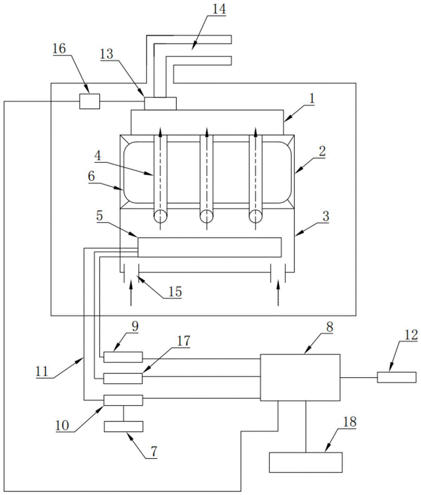
Fig. 1 is a schematic view of the overall structure of a full-automatic intelligent gas warmer provided by an embodiment of the present invention.
In the figure: 1. an exhaust gas chamber; 2. a heat exchange chamber; 3. a combustion chamber; 4. a copper pipe; 5. fire grate; 6. a cross-flow fan; 7. (ii) a A source of combustible gas; 8. a controller; 9. an igniter; 10. a gas proportional valve; 11. a combustible gas delivery pipe; 12. a temperature sensor; 13. an air draft fan; 14. a chimney; 15. an air inlet; 16. a wind pressure switch; 17. a thermocouple; 18. a display screen.
Detailed Description
The present invention is described in terms of particular embodiments, other advantages and features of the invention will become apparent to those skilled in the art from the following disclosure, and it is to be understood that the described embodiments are merely exemplary of the invention and that it is not intended to limit the invention to the particular embodiments disclosed. All other embodiments, which can be derived by a person skilled in the art from the embodiments given herein without making any creative effort, shall fall within the protection scope of the present invention.
Examples
As shown in fig. 1, the invention provides a full-automatic intelligent gas warmer, which is applied to indoor warming and comprises a machine body, a heat exchange unit and a control unit, and the full-automatic intelligent gas warmer is specifically arranged as follows:
the inside of organism is from last to forming mutually independent exhaust chamber 1, heat transfer room 2 and combustion chamber 3 respectively down, and exhaust chamber 1 and combustion chamber 3 all are to seal the setting, and heat transfer room 2 is the intercommunication setting with the external world. The heat exchange unit comprises a copper pipe 4, a fire grate 5 and a cross-flow fan 6, wherein the copper pipe 4 is vertically arranged in the heat exchange chamber 2, the top end of the copper pipe 4 is communicated to the waste gas chamber 1, and the bottom end of the copper pipe 4 is communicated to the combustion chamber 3. The fire grate 5 is arranged below the bottom end of the copper pipe 4 in the combustion chamber 3, and a combustible gas source 7 connected with the fire grate 5 is arranged outside the machine body, so that the heating direction of the fire grate 5 faces the bottom end of the copper pipe 4. The cross-flow fan 6 is arranged at one side of the copper pipe 4 in the heat exchange chamber 2, and the blowing direction of the cross-flow fan 6 faces to the communication position of the heat exchange chamber 2 and the outside. The control unit is arranged outside the machine body and comprises a controller 8, and the controller 8 is respectively connected with the fire grate 5 and the cross flow fan 6 through electric wires. The combustion chamber 3 is internally ignited with combustible gas through the fire grate 5 to heat the bottom end of the copper pipe 4, so that heat generated by combustion of the combustible gas is distributed on the copper pipe 4, and the heat on the copper pipe 4 is brought to indoor air through the cross-flow fan 6 to form heat exchange, thereby achieving the effect of warming.
Further, copper pipe 4 is both ends open-ended tubular structure, and it is provided with a plurality of, and a plurality of copper pipe 4 is line array and distributes in heat transfer chamber 2 to through a plurality of copper pipe 4, fully conduct the heat of burning in the combustion chamber 3 to in the heat transfer chamber 2. Wherein, heat transfer chamber 2 is the open setting with external intercommunication in the front side of copper pipe 4, and cross-flow fan 6 installs the rear side at copper pipe 4 to in heat on the copper pipe 4 is taken to indoor air to cross-flow fan 6, in order to form the heat exchange, and through the setting of this structure, make combustion chamber 3 not communicate with indoor, directly avoided the potential safety hazard that the gas was revealed.
As mentioned above, the control unit further includes the igniter 9, the igniter 9 is connected with the fire grate 5 through an electric wire, and the controller 8 is connected with the igniter 9 through an electric wire, the operating state of the igniter 9 is controlled through the controller 8, and then the fire grate 5 is controlled to ignite the combustible gas after the igniter 9 is started, so as to realize the automatic control of the fire grate 5.
Further, the control unit further comprises a gas proportional valve 10, the combustible gas source 6 is connected with the fire grate 5 through a combustible gas pipe 11, the gas proportional valve 10 is installed on a pipeline of the combustible gas pipe 11, and the controller 8 is connected with the gas proportional valve 10 through an electric wire. Meanwhile, the control unit further comprises a temperature sensor 12, the temperature sensor 12 is installed indoors, the controller 8 is connected with the temperature sensor 12 through an electric wire, and the temperature sensor 12 is linked with the gas proportional valve 10 under the control of the controller 8. That is, by providing this mechanism, the controller 8 automatically adjusts the opening degree of the gas proportional valve 10 according to the indoor temperature sensed by the temperature sensor 12 to control the amount of gas intake, and thus the amount of fire of the fire grate 5.
A preferred embodiment: an exhaust fan 13 is arranged on the outer side of the machine body above the waste gas chamber 1, the air inlet end of the exhaust fan 13 is communicated to the waste gas chamber 1, and the air outlet end of the exhaust fan 13 is communicated to the outside through a chimney 14, so that waste gas generated by combustion in the combustion chamber 3 enters the waste gas chamber 1 through a copper pipe 4 and is forcibly discharged out of the chamber through the exhaust fan 13. Simultaneously, be equipped with the air inlet 15 with external intercommunication in the bottom of combustion chamber 3, through the setting of this structure, after exhaust fan 13 forces to take out the burning waste gas in the exhaust chamber 1, make synchronous negative pressure that produces in the combustion chamber 3 to make indoor air pass through air inlet 15 and get into in the combustion chamber 3, in order to supply the oxygen that the burning needs. Wherein, the chimney 14 is a double-layer structure to avoid the leakage of waste gas. Preferably, the chimney 14 is connected to the exhaust gas treatment device outdoors.
Further, the control unit further comprises a wind pressure switch 16, the wind pressure switch 16 is connected with the air draft fan 13 through an electric wire, and the controller 8 is connected with the wind pressure switch 16 through an electric wire. Meanwhile, the control unit further comprises a thermocouple 17, the thermocouple 17 is connected with the fire grate 5 through a wire, and the controller 8 is connected with the thermocouple 17 through a wire. After the controller 8 intelligently controls the fire row 5 to ignite, the gas leakage safety is ensured through the thermocouple 17 and the wind pressure switch 16 on the exhaust fan 13.
A preferred embodiment: the control unit further comprises a display screen 18, the display screen 18 is connected with the controller 8 through an electric wire, a man-machine interaction interface is pre-installed on the display screen 18, the display screen 18 is preferably a liquid crystal display screen, the indoor temperature condition and the working state of each functional module can be conveniently displayed on the display screen 18 through the arrangement of the display screen 18, and the working state of each functional module can be conveniently controlled or adjusted by a user at any time through the man-machine interaction interface.
A preferred embodiment: the invention provides a gas heating control method, which adopts the full-automatic intelligent gas heater of the embodiment and comprises the following steps:
s1, a user sends starting instructions of the fire grate 5, the cross-flow fan 6 and the air draft fan 13 to the controller 8 through a human-computer interaction interface on the display screen 18, and the controller 8 starts the fire grate 5, the cross-flow fan 6 and the air draft fan 13 in sequence according to the received starting instructions;
s2, after the fire grate 5 is started, acquiring an indoor temperature signal in real time by an indoor pre-installed temperature sensor 12, transmitting the temperature signal to the controller 8, feeding the received temperature signal back to the display screen 18 by the controller 8, displaying an indoor temperature value by the display screen 18, and automatically adjusting the opening degree of a gas proportional valve 10 on a combustible gas delivery pipe 11 by the controller 8 according to the received temperature signal to control the fire power of the fire grate 5;
s3, after the cross flow fan 6 brings the heat of the copper tube 4 into the indoor air for heat exchange, the user judges whether the current indoor temperature meets the heating requirement according to the indoor temperature value displayed on the display screen 18, and if the current indoor temperature does not meet the heating requirement, the user adjusts the wind speed of the cross flow fan 6 in real time through the human-computer interaction interface on the display screen 18 to control the heat for heat exchange.
Further, in step S2, a temperature threshold is preset in the controller 8, and the controller 8 performs a comparison analysis according to the temperature value of the temperature signal and the temperature threshold;
when the temperature value is higher than the temperature threshold value, the controller 8 automatically adjusts the opening degree of the gas proportional valve 10 on the combustible gas delivery pipe 11 to be smaller;
when the temperature value is lower than the temperature threshold value, the controller 8 automatically adjusts the opening degree of the gas proportional valve 10 on the gas transmission pipe 11 to be increased.
Further, the user starts the exhaust fan 13 through the man-machine interface on the display screen 18, and simultaneously the wind power that the fan operation produced is responded to by the wind pressure switch 16 to according to the wind power signal of response, feed back the wind power signal to the controller 8, the controller 8 is according to the operating condition that the wind power signal control fire was arranged 5 of receiving:
when the wind pressure switch 16 senses wind power generated by the running of the fan, the controller 8 controls the igniter 9 to start the fire grate 5;
when the wind pressure switch 16 does not sense the wind power generated by the running of the fan, the controller 8 controls the gas proportional valve 10 to close the fire grate 5.
The invention sets fire row 5 to ignite combustible gas in the combustion chamber 3 to heat the bottom end of the copper tube 4, so that the heat generated by the combustion of the gas is distributed on the copper tube 4, and the cross flow fan 6 is arranged behind the copper tube 4, and the heat on the copper tube 4 is brought to the indoor air by the cross flow fan 6 to form heat exchange.
Although the invention has been described in detail above with reference to a general description and specific examples, it will be apparent to one skilled in the art that modifications or improvements may be made thereto based on the invention. Accordingly, such modifications and improvements are intended to be within the scope of the invention as claimed.