Disclosure of Invention
The invention aims to solve at least one of the problems in the prior related art to a certain extent, and therefore the invention provides a noise reduction device which is simple and ingenious in structure, can capture, store and consume sound energy of wave crests, and improves sound absorption efficiency.
The invention also provides a range hood with the noise reduction device. The invention also provides a control method of the range hood.
According to the noise reduction device provided by the above, the following technical scheme is adopted to realize:
a noise reducing device comprising: the sound absorption switch comprises a first sound absorption component and a second sound absorption component, the second sound absorption component is arranged on at least one outer side of the first sound absorption component, and a sound absorption cavity which can be opened or closed is formed between the second sound absorption component and the first sound absorption component; the output end of the driving component is connected with the first sound absorption component and/or the second sound absorption component, and the driving component is used for driving the second sound absorption component and the first sound absorption component to move close to each other according to the wave crests of sound waves so as to seal the sound absorption cavity, and is also used for driving the second sound absorption component and the first sound absorption component to move away from each other according to the wave troughs of the sound waves so as to open the sound absorption cavity.
In some embodiments, the first sound absorbing assembly includes a first connecting rod and at least two positioning members, all of the positioning members being spaced apart along a length direction of the first connecting rod, each positioning member being connected to the first connecting rod; the second sound absorption assembly comprises second connecting pieces and moving pieces equal to the number of the positioning pieces, all the moving pieces and all the positioning pieces are arranged in a one-to-one correspondence mode, each moving piece is connected with the second connecting piece, and openable or closed sound absorption cavities are formed between the adjacent positioning pieces and the moving pieces.
In some embodiments, the first sound absorption assembly is a positioning member, the second sound absorption assembly is a moving member, and the sound absorption cavity which can be opened or closed is formed between the positioning member and the moving member.
In some embodiments, the moving member is provided with a first groove opening towards the positioning member, and the sound absorption cavity is formed by the first groove and a surface of the positioning member facing the first groove in a surrounding manner; or the positioning piece is provided with a second groove which is opened towards the moving piece, and the sound absorption cavity is formed by the second groove and one surface of the moving piece facing the second groove in a surrounding manner; or, the moving piece is provided with a first groove facing the opening of the positioning piece, the second groove is arranged at the position of the positioning piece corresponding to the first groove, and the sound absorption cavity is formed by the first groove and the second groove in a surrounding manner.
In some embodiments, a buffer or seal is located between the positioning member and the moving member, the buffer or seal being located outside the sound-absorbing chamber.
In some embodiments, the sound absorption device further comprises two fixing assemblies arranged side by side at intervals, two opposite ends of the first sound absorption assembly are respectively connected with the two fixing assemblies, and two opposite ends of the second sound absorption assembly are respectively connected with the two fixing assemblies in a sliding manner; the output end of the driving assembly is connected with the second sound absorption assembly.
In some embodiments, at least two sound absorption switches are arranged between two fixing assemblies at intervals side by side along the length direction of the fixing assemblies, the first sound absorption assembly of each sound absorption switch is fixedly connected with the fixing assemblies, and the second sound absorption assembly of each sound absorption switch is slidably connected with the fixing assemblies; and the output end of the driving assembly is respectively connected with all the second sound absorption assemblies of the sound absorption switch.
In some embodiments, an auxiliary sound absorption chamber that can be opened or closed may be formed between adjacent sound absorption switches.
In some embodiments, the fixing assembly comprises a fixing seat and a sliding block, the fixing seat is provided with a sliding groove arranged along the length direction of the fixing seat, the side wall of the fixing seat facing the second sound absorption assembly is provided with a guide groove, the guide groove is communicated with the sliding groove, and the sliding block is movably arranged in the sliding groove; the end part of the second sound absorption assembly penetrates through the guide groove and is connected with the sliding block, or the sliding block is provided with an extension part facing the second sound absorption assembly, and the extension part penetrates through the guide groove and is connected with the second sound absorption assembly; the output end of the driving assembly is connected with one of the sliding blocks.
In some embodiments, the slider is provided with a connecting portion extending outward, an opening arranged in the length direction is formed in a position of the fixing seat corresponding to the connecting portion, the connecting portion is movably inserted into the opening, and the output end of the driving assembly is connected with the connecting portion of one of the sliders.
In some embodiments, the device further comprises a connecting rod assembly, and the output end of the driving assembly is connected with one of the sliding blocks through the connecting rod assembly.
According to the range hood that provides above-mentioned, it realizes through following technical scheme:
a range hood, comprising: the smoke collecting hood is provided with an air inlet; the air cabinet assembly is arranged at the top of the fume collecting hood; the sound wave detection assembly is arranged on the smoke collecting hood or the air cabinet assembly and is used for acquiring a noise signal generated by the work of the range hood; a noise reducer as above, said noise reducer being mounted at said air inlet; and the control assembly is respectively and electrically connected with the air cabinet assembly, the driving assembly of the noise reduction device and the sound wave acquisition module.
According to the control method of the range hood, the control method is realized through the following technical scheme:
a control method of a range hood, wherein the control method comprises the following steps:
s1, starting the range hood, and opening the air cabinet assembly;
s2, determining the working gear of the range hood, and acquiring a noise signal generated by the operation of the range hood, wherein the noise signal comprises a sound wave waveform;
s3, determining the optimal working parameters of the driving component according to the acquired noise signals, wherein the optimal working parameters comprise the optimal rotating speed or the optimal moving frequency;
and S4, controlling the driving component to work according to the determined optimal working parameters.
In some embodiments, determining the optimal operating parameter of the drive assembly based on the acquired noise signal comprises: analyzing the obtained noise signal to obtain the peak frequency of the range hood; and determining the optimal working parameters of the driving assembly according to the peak frequency.
In some embodiments, the control drive assembly operates in accordance with the determined optimal operating parameters, which includes:
s41, controlling the driving assembly to start working from different initial positions;
s42, acquiring noise values of the driving assembly working for a circle according to the optimal working parameters under different initial positions to obtain a noise value data set;
s43, extracting the minimum value in the noise value data set, and taking the initial position corresponding to the minimum value as the optimal initial position;
and S45, controlling the driving assembly to work according to the optimal initial position and the optimal working parameters.
In some embodiments, the control method further comprises the steps of: s5, judging whether the working gear of the range hood changes or not, and judging whether the range hood is closed or not, if the range hood is not closed and the working gear does not change, returning to the step S4; if the range hood is not closed and the working gear is changed, returning to the step S2; if the range hood is closed, the driving assembly and the air cabinet assembly are closed.
Compared with the prior art, the invention at least comprises the following beneficial effects:
according to the noise reduction device, the openable or closed sound absorption cavity is formed between the second sound absorption assembly and the first sound absorption assembly, the driving assembly can drive the second sound absorption assembly and the first sound absorption assembly to move relatively according to the wave crest and the wave trough of sound waves, the sound absorption cavity is closed when the wave crest of the sound waves is reached, sound energy of the wave crest is grabbed, stored and consumed, indexes such as noise of a smoke machine are obviously reduced, and the sound absorption cavity is opened when the wave trough of the sound waves, so that preparation is made for grabbing and storing the wave crest of the next sound waves.
Detailed Description
The present invention is illustrated by the following examples, but the present invention is not limited to these examples. Modifications to the embodiments of the invention or equivalent substitutions of parts of technical features without departing from the spirit of the invention are intended to be covered by the scope of the claims of the invention.
Example 1
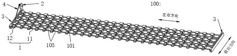
Referring to fig. 1, the present embodiment provides a noise reduction device, which can be applied to a range hood, the noise reduction device 100 at least includes a sound absorption switch 1 and a driving component 2, where the sound absorption switch 1 includes a first sound absorption component 11 and a second sound absorption component 12, a second sound absorption component 12 is disposed on at least one of two opposite outer sides of the first sound absorption component 11, and a sound absorption cavity 101 that can be opened or closed is formed between the second sound absorption component 12 and the first sound absorption component 11. In this embodiment, the two opposite outer sides of the first sound absorbing assembly 11 specifically refer to two opposite outer sides of the first sound absorbing assembly 11 in the front-back direction, and in this embodiment, a second sound absorbing assembly 12 is disposed on the front side of the first sound absorbing assembly 11 as an example.
The output end of the driving component 2 is connected with the first sound absorption component 11 and/or the second sound absorption component 12, and the driving component is used for driving the second sound absorption component 12 to move close to the first sound absorption component 11 according to the wave crest of the sound wave so as to seal the sound absorption cavity 101; and is also used for driving the second sound absorption assembly 12 and the first sound absorption assembly 11 to move away from each other according to the wave troughs of the sound waves so as to open the sound absorption cavity 101.
In the sound absorption and noise reduction process, the driving component 2 can drive the first sound absorption component 11 and the second sound absorption component 12 to move relatively according to the wave crests and the wave troughs of sound waves so as to realize the grabbing, storing and thoroughly absorbing the sound energy of the wave crests. The specific working principle of the noise reducer 100 is as follows: in the sound wave propagation process, when the wave crest of the sound wave, the driving component 2 drives the second sound absorption component 12 and the first sound absorption component 11 to move close to each other, so that a sound absorption cavity 101 formed between the second sound absorption component 12 and the first sound absorption component 11 is closed, at the moment, the sound energy of the wave crest is captured and stored in the closed sound absorption cavity 101 and is rapidly consumed in the closed sound absorption cavity 101, and the sound absorption efficiency is improved; when the wave trough of sound wave, drive second sound absorption subassembly 12 and first sound absorption subassembly 11 back-to-back motion to make the sound absorption chamber 101 that forms between second sound absorption subassembly 12 and the first sound absorption subassembly 11 open, sound absorption chamber 101 is in the open mode this moment, is convenient for snatch, save and consume the crest of next sound wave.
It can be seen that, in the noise reducer 100 of this embodiment, the openable or closable sound-absorbing cavity 101 is formed between the second sound-absorbing component 12 and the first sound-absorbing component 11, and the driving component 2 can drive the second sound-absorbing component 12 and the first sound-absorbing component 11 to move relatively according to the wave crest and the wave trough of the sound wave, so that the sound-absorbing cavity 101 is closed at the wave crest of the sound wave, thereby realizing the capturing, storing and consuming of the sound energy of the wave crest, and realizing the significant reduction of indexes such as noise of the range hood, and the sound-absorbing cavity 101 is opened at the wave trough of the sound wave to prepare for capturing and storing the wave crest of the next sound wave.
Further, the structures of the first sound absorbing assembly 11 and the second sound absorbing assembly 12 include, but are not limited to, the following two:
first, referring to fig. 1-2, the first sound absorbing assembly 11 includes a first connecting rod 112 and at least two positioning members 111, all the positioning members 111 are arranged at intervals along the length direction of the first connecting rod 112, each positioning member 111 is connected to the first connecting rod 112, that is, at least two positioning members 111 arranged at intervals are connected in series to the first connecting rod 112, and a space for passing air flow (for example, oil smoke) is formed between adjacent positioning members 111. The second sound absorption assembly 12 comprises a second connecting piece 122 and moving pieces 121 equal to the number of the positioning pieces 111, all the moving pieces 121 and all the positioning pieces 111 are arranged in a one-to-one correspondence manner, each moving piece 121 is connected with the second connecting piece 122, namely the second connecting piece 122 is also connected with at least two moving pieces 121 in series, an interval for air flow to pass through is also formed between every two adjacent moving pieces 121, and each moving piece 121 and the rear side and the adjacent positioning piece 111 thereof form a pair of sub sound absorption switches. An openable or closable sound absorbing chamber 101 is formed between the adjacent positioning member 111 and the moving member 121. From this, sound absorption switch 1 comprises many pairs of sub sound absorption switch, and every pair of sub sound absorption switch all has one and can open or confined sound absorption chamber 101, effectively increases sound absorbing area to do benefit to snatching, storage and the thorough absorbed dose of the sound energy that promotes the crest, show and promote sound absorption noise reduction effect. In addition, except that the space between the adjacent positioning parts 111 and the space between the adjacent moving parts 121 can be used for air flow to pass through, the gap formed in the relative motion process of the moving parts 121 and the positioning parts 11 can also be used for air flow to pass through, so that the sound absorption switch 1 is ensured to have larger porosity, and the unit ventilation area is improved.
The output end of the driving assembly 2 is connected to the second connecting member 122 and/or the first connecting rod 112. When the driving assembly 2 drives the first sound absorption assembly 11 and the second sound absorption assembly 12 to move relatively, the sound absorption cavities 101 of the pairs of sound absorption switches are opened or closed synchronously.
Secondly, referring to fig. 3, the first sound absorbing assembly 11 is a positioning member 111 having a certain length, the second sound absorbing assembly 12 is a moving member 121, and an openable or closable sound absorbing chamber 101 is formed between the positioning member 111 and the moving member 121. The output end of the driving assembly 2 is connected with the connecting shaft 106 of the positioning member 111 and/or the connecting shaft 106 of the moving member 121. Therefore, compared with the first technical scheme, the sound absorption cavity 101 formed by the second technical scheme has larger area, so that the unit grasping amount of sound energy of wave crests is larger, and the sound absorption and noise reduction effects are better.
Further, the sound-absorbing chamber 101 is formed in a manner including, but not limited to, the following:
in the first forming mode, a first groove 103 opening toward the positioning member 111 is formed on one side of the moving member 121 facing the positioning member 111, and the sound-absorbing cavity 101 is formed by surrounding the first groove 103 and one surface of the positioning member 111 facing the first groove 103. When the wave crest of the sound wave, the driving component 2 drives the moving member 121 and the positioning member 111 to move close to each other, when the moving member 121 abuts against the positioning member 111, the positioning member 111 covers the opening of the first groove 103 to form the closed sound absorption cavity 101, and at this time, the sound energy of the wave crest is captured and stored in the closed sound absorption cavity 101 and is rapidly consumed in the closed sound absorption cavity 101. When the wave trough of the sound wave, the driving component 2 drives the moving member 121 and the positioning member 111 to move away from each other, so that the positioning member 111 does not cover the opening of the first groove 103, and at this time, the sound absorption cavity 101 is opened, which is convenient for grabbing the wave crest of the next sound wave.
In the second forming mode, a second groove 104 opened toward the moving member 121 is formed on one side of the positioning member 111 facing the moving member 121, and the sound-absorbing cavity 101 is formed by surrounding the second groove 104 and one surface of the moving member 121 facing the second groove 104. When the positioning piece 111 and the moving piece 121 are folded to abut against each other, the sound absorption cavity 101 is closed; when the positioning member 111 is separated from the moving member 121 and does not abut against the moving member, the sound absorbing chamber 101 is opened.
In a third forming manner, referring to fig. 2 or fig. 3, a first groove 103 opening toward the positioning member 111 is disposed on a side of the moving member 121 facing the positioning member 111, a second groove 104 is disposed at a position of the positioning member 111 corresponding to the first groove 103, and the sound-absorbing cavity 101 is formed by the first groove 103 and the second groove 104.
The sound-absorbing chamber 101 of the present embodiment is exemplified by the third formation manner. Referring to fig. 1 and 4, the positioning member 111 includes a fixing block 1101 and two first blocking plates 1102, wherein opposite sides of the fixing block 1101 in a front-rear direction are respectively provided with a groove recessed toward the inside thereof, the groove having left and right sides and a front or rear side opening. The two first baffle plates 1102 are respectively and fixedly connected to the left side wall and the right side wall of the fixing block 1101, left openings of the two grooves are covered by the left first baffle plate 1102, and right openings of the two grooves are covered by the right first baffle plate 1102.
Referring to fig. 1 and 5, the moving member 121 includes a moving block 1201 and four second stoppers 1202, wherein opposite sides of the moving block 1201 in the front-rear direction are respectively provided with grooves recessed toward the inside thereof, each groove having left and right sides and a front or rear side opening. The second blocking plates 1202 are paired in pairs, wherein one pair of the second blocking plates 1202 is fixedly connected to the left side wall of the moving block 1201 and covers the left openings of the two grooves, and the other pair of the second blocking plates 1202 is fixedly connected to the right side wall of the moving block 1201 and covers the right openings of the two grooves.
In other embodiments, the four second shutters 1202 may be replaced by two cover plates with larger areas, wherein one cover plate covers the left openings of the two grooves of the moving block 1201, and the other cover plate covers the right openings of the two grooves of the moving block 1201.
Referring to fig. 2 or 3, further, between the positioning member 111 and the moving member 121, a buffer portion 102 or a sealing portion is located outside the sound-absorbing chamber 101. In this embodiment, the buffer portions 102 are respectively disposed on the upper and lower side wall edges of the first groove 103, and the buffer portions 102 are respectively disposed on the upper and lower side wall edges of the second groove 104. Therefore, the buffer part 102 can not only play a role of buffering when the positioning part 111 and the moving part 121 move close to each other, but also improve the sealing effect of the sound absorption cavity 101 to a certain extent.
In other embodiments, the buffer 102 on the first groove 103 or the second groove 104 may be omitted. Of course, a buffer rubber or a sealing ring in a ring structure may be disposed around the first groove 103 and/or around the second groove 104 to improve the sealing effect of the sound-absorbing cavity 101.
Referring to fig. 1, further, the sound absorption device further includes two fixing assemblies 3 arranged side by side at intervals, two opposite ends of the first sound absorption assembly 11 are respectively and fixedly connected with the two fixing assemblies 3, and two opposite ends of the second sound absorption assembly 12 are respectively and slidably connected with the two fixing assemblies 3. The output end of the drive assembly 2 is connected to the second connector 122 of the second sound absorbing assembly 12. Therefore, the fixing component 3 is additionally arranged, so that the fixing of the first sound absorption component 11 is facilitated, and the movement of the second sound absorption component 12 is guided.
In this embodiment, be equipped with between two fixed subassemblies 3 along its length direction at least two sound absorption switches 1 of interval arrangement side by side, the fixed subassembly 3 of first sound absorption subassembly 11 fixed connection of every sound absorption switch 1 to the fixed subassembly 3 of second sound absorption subassembly 12 sliding connection of every sound absorption switch 1, like this, through a plurality of sound absorption switches 1, make the whole sound-absorbing cavity 101 of the device of making an uproar bigger, do benefit to and promote the sound absorption noise reduction effect of unit. The output ends of the driving components 2 are respectively connected with the second sound absorption components 12 of all the sound absorption switches 1. Therefore, the driving component 2 can drive all the second sound absorption components 12 to move synchronously and directionally, so that the on-off state of the sound absorption cavities 101 of all the sound absorption switches 1 can be synchronously adjusted.
In addition, an auxiliary sound absorbing chamber that can be opened or closed is formed between adjacent sound absorbing switches 1, that is, an openable and closable sound absorbing chamber 101 is formed between each positioning member 111 and its adjacent front side movable member 121, and an openable and closable auxiliary sound absorbing chamber is formed between each positioning member 111 and its adjacent rear side movable member 121. When the driving assembly 2 drives the moving member 121 to move backward, the sound-absorbing chamber 101 at the front side of each positioning member 111 is closed, and the auxiliary sound-absorbing chamber at the rear side is opened; on the contrary, when the moving member 121 is driven to move forward, the sound-absorbing chamber 101 at the front side of each positioning member 111 is opened, and the auxiliary sound-absorbing chamber at the rear side is closed. Of course, by properly designing the distance between adjacent sound-absorbing switches 1, when the sound-absorbing chamber 101 at the front side of each positioning member 111 is fully opened, the auxiliary sound-absorbing chamber at the rear side is not closed.
Referring to fig. 1 and 6-7, further, the fixing assembly 3 includes a fixing seat 31 and a sliding block 32, the fixing seat 31 is provided with a sliding groove 311 arranged along a length direction thereof, and a side wall of the fixing seat 31 facing the second sound absorbing assembly 12 is provided with a guide groove 312, the guide groove 312 is communicated with the sliding groove 311, and the sliding block 32 is movably disposed in the sliding groove 311. In this embodiment, the end of each second sound absorbing assembly 12 passes through the guide slot 312 and is connected to the slider 32. The output end of the driving component 2 is connected to one of the sliders 32, and in this embodiment, the output end of the driving component 2 is connected to the left slider 32 as an example. Therefore, the slide block 32 and the second sound absorption assembly 12 which are connected are used, and the output end of the driving assembly 2 is connected with the slide block 32 close to the left, so that the driving assembly 2 can synchronously drive the front and back movement of all the second sound absorption assemblies 12 through the slide block 32 close to the left, and the on-off state of all the sound absorption cavities 101 is synchronously controlled.
In other embodiments, an extension toward the second sound absorbing assembly 12 may be added to the slider 32 and pass through the guide channel 312 and connect the second sound absorbing assembly 12.
The sliding slot 311 of the present embodiment is preferably a T-shaped slot, and the sliding block 32 is a T-shaped structure matched with the T-shaped slot, so that the sliding block 32 is reliably installed in the sliding slot 311 by the structural design of the sliding slot 311 and the sliding block 32 itself, and the sliding block 32 is prevented from being released in the vertical direction. In addition, the sliding groove 311 can be prevented from coming out from the front and rear direction of the sliding groove 311 by the limit of the front and rear end portions of the guide groove 312 and the connection relationship between the second sound absorption member 12 and the sliding groove 311.
Furthermore, a connecting portion 321 extending outward is disposed on the top of the sliding block 32, an opening 313 arranged along the length direction of the fixing base 31 is disposed at a position corresponding to the connecting portion 321, and the connecting portion 321 is movably inserted into the opening 313. The output end of the driving assembly 2 is connected to the connecting portion 321 of the left slider 32.
Referring to fig. 1, further, a connecting rod assembly 4 is further included, and the driving assembly 2 is preferably a rotating motor, and an output end of the rotating motor is connected to the connecting portion 321 of the left slider 32 through the connecting rod assembly 4.
In other embodiments, the connecting rod assembly 4 may be omitted, and the driving assembly 2 is replaced by a push rod motor, and the output end of the push rod motor is directly connected to the connecting portion 321 near the left slider 32, so that the overall structure of the noise reduction device is simpler.
Example 2
Referring to fig. 8, the present embodiment provides a range hood, which includes a smoke collecting hood 5, a wind cabinet assembly 6, a noise reduction device as described in embodiment 1, and a control assembly (not shown in the drawings). The bottom of the fume collecting hood 5 is provided with an air inlet 501 for the oil fume to pass through. The wind cabinet assembly 6 is disposed on top of the fume collecting hood 5 and communicates with each other. The noise reduction device is installed at the air inlet 501. The control assembly is respectively and electrically connected with the air cabinet assembly 6 and the driving assembly 2 of the noise reduction device, and is used for controlling the working state of the driving assembly 2 according to the wave crest and the wave trough of the noise generated by the work of the range hood, so that the noise reduction device can grab, store and consume the sound energy of the wave crest in the noise, the wave crest of the sound wave is prevented from escaping outwards, indexes such as the noise of the range hood are obviously reduced, the user experience degree is improved, and the product competitiveness of a company is improved.
The noise reduction device of this embodiment, it has certain porosity, can carry out rational design through the size to the device of making an uproar, makes it can cover air intake 501, and the device of making an uproar not only can prevent that the noise from expanding outward this moment, reduces the noise index of cigarette machine, but also can replace traditional oil net, like this, can save traditional oil net, reduces and makes with material and manufacturing cost.
Further, a smoke baffle 502 for opening or closing the air inlet 501 is further provided on the smoke collecting hood 5.
In this embodiment, the range hood further includes a sound wave obtaining module (not shown in the figure) electrically connected to the control assembly, and the sound wave detecting assembly is disposed on the smoke collecting hood 5 or the wind cabinet assembly 6 and is used for obtaining a noise signal generated by the operation of the range hood. When the range hood is started to work, a noise signal generated by the work of the range hood can be acquired through the sound wave acquisition module; analyzing the obtained noise signal to obtain the peak frequency of the range hood; determining the optimal working parameters of the driving component 2 according to the peak frequency; the drive assembly 2 is controlled to operate in accordance with the determined optimum operating parameters.
The driving component 2 works according to the determined optimal working parameters, when the wave crest of the sound wave, the second sound absorption component 12 and the first sound absorption component 11 are driven to move close to each other, so that the sound absorption cavity 101 is closed, the sound energy of the wave crest is grabbed and stored in the closed sound absorption cavity 101, the sound is quickly consumed in the closed sound absorption cavity 101, the sound absorption and noise reduction effects are achieved, and the noise is prevented from expanding outwards. When the wave trough of the sound wave, the second sound absorption assembly 12 is driven to move away from the first sound absorption assembly 11, so that the sound absorption cavity 101 is opened, and the sound energy of the wave crest can be grabbed, stored and consumed next time.
Example 3
Referring to fig. 9, the present embodiment provides a control method of a range hood, which is applied to the range hood described in embodiment 2, and the control method includes the following steps:
a control method of a range hood, wherein the control method comprises the following steps:
s1, starting the range hood, and opening the air cabinet assembly 6;
s2, determining the working gear of the range hood, and acquiring a noise signal generated by the operation of the range hood, wherein the noise signal comprises a sound wave waveform;
specifically, according to the current running state of the air cabinet assembly 6, the control assembly determines the current working gear of the range hood, and acquires a noise signal generated by the operation of the air cabinet assembly 6 of the range hood through the sound wave acquisition module, wherein the noise signal includes a sound wave waveform and a noise value.
S3, determining the optimal operating parameters of the driving assembly 2 according to the obtained noise signal, wherein the optimal operating parameters include the optimal rotating speed or the optimal moving frequency;
specifically, according to the obtained noise signal, the control component analyzes the obtained noise signal to obtain the peak frequency of the range hood. The optimum operating parameters of the drive assembly 2 are then determined from the peak frequency obtained by the analysis.
When the driving assembly 2 is a rotating motor, the rotating motor is connected to the connecting portion 321 of the left slider 32 through the connecting rod assembly 4, so that the rotating motor can drive the left slider 32 to reciprocate by rotating, and further drive the moving member 121 to reciprocate, thereby controlling the opening or closing of the sound-absorbing cavity 101. At this time, the optimum operating parameter corresponds to the optimum rotational speed.
When the driving assembly 2 is a push rod motor, the push rod motor is directly connected to the connecting portion 321 of the left slider 32, so that the push rod of the push rod motor can synchronously move to and fro along the left slider 32, and further move the moving member 121 to move to and fro, thereby controlling the opening or closing of the sound-absorbing cavity 101. At this time, the optimal operating parameter corresponds to the optimal moving frequency.
And S4, controlling the driving component 2 to work according to the determined optimal working parameters.
Specifically, the operation of the driving assembly 2 is controlled according to the determined optimal operating parameters, so as to control the opening or closing of the sound absorption cavity 101 and ensure that the opening or closing of the sound absorption cavity 101 is matched with the peak frequency. Namely, when the wave crest of the sound wave, the driving component 2 drives the second sound absorption component 12 and the first sound absorption component 11 to move close to each other, so that the sound absorption cavity 101 is closed, the sound energy of the wave crest is captured and stored in the closed sound absorption cavity 101, and the sound energy is quickly consumed in the closed sound absorption cavity 101. When the wave trough of the sound wave, the second sound absorption assembly 12 and the first sound absorption assembly 11 are driven to move away from each other, so that the sound absorption cavity 101 is opened, and the sound absorption cavity 101 can grab the wave crest of the next sound wave.
Referring to fig. 10, in the present embodiment, the control drive assembly 2 operates according to the determined optimal operating parameters, which include:
s41, controlling the driving assembly 2 to start working from different initial positions;
s42, acquiring noise values of the driving assembly 2 working for a circle according to the optimal working parameters under different initial positions to obtain a noise value data set;
s43, extracting the minimum value in the noise value data set, and taking the initial position corresponding to the minimum value as the optimal initial position;
and S45, controlling the driving assembly 2 to work according to the optimal initial position and the optimal working parameters.
Therefore, by acquiring the noise value of the driving component 2 which operates for one circle according to the optimal working parameter under different initial positions to obtain the minimum value in the noise value data set and taking the initial position corresponding to the minimum value as the optimal initial position, the optimal initial position of the driving component 2 is adjusted in a self-adaptive manner, so that the opening or closing of the sound absorption cavity 101 is ensured to be highly matched with the peak frequency, the absorption and noise reduction effects on the peak sound energy are further improved, and the indexes of the smoke machine such as noise are reduced.
Referring to fig. 9, further, the control method further includes the steps of: s5, judging whether the working gear of the range hood changes or not, and judging whether the range hood is closed or not, if the range hood is not closed and the working gear does not change, returning to the step S4; if the range hood is not closed and the working gear is changed, returning to the step S2; if the range hood is closed, the drive assembly 2 and the hood assembly 6 are closed. Therefore, by monitoring the working gear and the switching condition of the range hood, when the range hood is not closed and the working gear is not changed, the driving assembly 2 is controlled to continuously work according to the determined optimal working parameter; when the range hood is not closed and the working gear is changed, new optimal working parameters corresponding to the working gear of the range hood are obtained again, and then the driving assembly 2 is controlled to work according to the new optimal working parameters, so that the sound absorption and noise reduction effects of the noise reduction device on the wave peak sound energy are ensured.
What has been described above are merely some embodiments of the present invention. It will be apparent to those skilled in the art that various changes and modifications can be made without departing from the inventive concept thereof, and these changes and modifications can be made without departing from the spirit and scope of the invention.