CN113684906B - Profound system drainage structure and use method - Google Patents
Profound system drainage structure and use method Download PDFInfo
- Publication number
- CN113684906B CN113684906B CN202110938488.2A CN202110938488A CN113684906B CN 113684906 B CN113684906 B CN 113684906B CN 202110938488 A CN202110938488 A CN 202110938488A CN 113684906 B CN113684906 B CN 113684906B
- Authority
- CN
- China
- Prior art keywords
- water
- ring
- pipe
- block
- shaped
- Prior art date
- Legal status (The legal status is an assumption and is not a legal conclusion. Google has not performed a legal analysis and makes no representation as to the accuracy of the status listed.)
- Active
Links
- 238000000034 method Methods 0.000 title claims abstract description 8
- XLYOFNOQVPJJNP-UHFFFAOYSA-N water Substances O XLYOFNOQVPJJNP-UHFFFAOYSA-N 0.000 claims abstract description 86
- 230000000903 blocking effect Effects 0.000 claims description 25
- 238000007789 sealing Methods 0.000 claims description 24
- 239000006185 dispersion Substances 0.000 claims description 23
- 230000003014 reinforcing effect Effects 0.000 claims description 18
- 230000000694 effects Effects 0.000 claims description 9
- 238000010030 laminating Methods 0.000 claims description 5
- 230000005484 gravity Effects 0.000 claims description 4
- 238000004804 winding Methods 0.000 claims description 3
- 238000007599 discharging Methods 0.000 claims 1
- 239000007787 solid Substances 0.000 description 8
- 210000003437 trachea Anatomy 0.000 description 6
- 230000007613 environmental effect Effects 0.000 description 2
- 241000607479 Yersinia pestis Species 0.000 description 1
- 238000009825 accumulation Methods 0.000 description 1
- 230000009286 beneficial effect Effects 0.000 description 1
- 230000003139 buffering effect Effects 0.000 description 1
- 239000012141 concentrate Substances 0.000 description 1
- 230000007547 defect Effects 0.000 description 1
- 238000010586 diagram Methods 0.000 description 1
- 238000011010 flushing procedure Methods 0.000 description 1
- 239000003673 groundwater Substances 0.000 description 1
- 230000002787 reinforcement Effects 0.000 description 1
- 239000002352 surface water Substances 0.000 description 1
Images




Classifications
-
- E—FIXED CONSTRUCTIONS
- E03—WATER SUPPLY; SEWERAGE
- E03F—SEWERS; CESSPOOLS
- E03F1/00—Methods, systems, or installations for draining-off sewage or storm water
-
- E—FIXED CONSTRUCTIONS
- E03—WATER SUPPLY; SEWERAGE
- E03F—SEWERS; CESSPOOLS
- E03F5/00—Sewerage structures
-
- E—FIXED CONSTRUCTIONS
- E03—WATER SUPPLY; SEWERAGE
- E03F—SEWERS; CESSPOOLS
- E03F5/00—Sewerage structures
- E03F5/04—Gullies inlets, road sinks, floor drains with or without odour seals or sediment traps
Landscapes
- Health & Medical Sciences (AREA)
- Life Sciences & Earth Sciences (AREA)
- Engineering & Computer Science (AREA)
- Hydrology & Water Resources (AREA)
- Public Health (AREA)
- Water Supply & Treatment (AREA)
- Structures Of Non-Positive Displacement Pumps (AREA)
Abstract
The invention discloses a deep system drainage structure and a use method thereof, the deep system drainage structure comprises a plurality of groups of vertical shafts, communicating pipes are fixedly communicated between two adjacent groups of vertical shafts, the communicating pipes are positioned at the lower part of the vertical shafts, U-shaped pipes are fixedly arranged on the inner walls of the vertical shafts positioned at the edges, one ends of the U-shaped pipes are positioned in the vertical shafts, the other ends of the U-shaped pipes are positioned at the outer sides of the vertical shafts, the height of one end of the U-shaped pipes positioned in the vertical shafts is higher than that of one end of the outer side of the vertical shafts under the same vertical line, a pressurizing part is arranged in the U-shaped pipes and positioned on the outer side wall of the vertical shafts, a discharge pipe extends at the other end of the U-shaped pipes, a fixing part is arranged at the outer side of the discharge pipe, a dispersing part extends at the side face of the fixing part, and the axle center of the dispersing part and the axle center of the discharge pipe are positioned on the same horizontal line. The phenomenon that the reservoir wall is broken due to water drainage can be avoided, and the firmness after assembly can be ensured while the use convenience is improved.
Description
Technical Field
The invention belongs to the field of drainage facilities, and particularly discloses a profound system drainage structure and a use method thereof.
Background
The disaster phenomenon that the ground water formed by rainfall affects the normal growth of crops is also called as 'sloshing'. Excessive or too concentrated rainwater, insufficient drainage capacity of the river channel, or difficult drainage due to jacking of external water, can cause surface water accumulation in low-lying areas. The surplus water quantity that produces the waterlogging disaster is called waterlogging, also called waterlogging (waterlogging pest), in order to avoid this phenomenon, people can install the shaft everywhere on ground in order to guide the waterlogging to the cistern through the shaft in order to concentrate the emission, however current adopts the water pump to keep working when the drainage to take out the water in the shaft and discharges, this kind of emission mode needs the water pump to keep working the power consumption great, seriously influences its feature of environmental protection, and simultaneously very easily erodees the pool wall of cistern because of the pressure of rivers is too big in the drainage process, causes the cistern to appear breaking under the erodeing of rivers for a long time.
Disclosure of Invention
The invention aims to solve the defects in the background art and provides a deep system drainage structure which solves the problems in the prior art.
In order to achieve the technical characteristics, the aim of the invention is realized in the following way: the utility model provides a profound system drainage structures, it includes multiunit shaft, two sets of fixed intercommunication has communicating pipe between the shaft, communicating pipe is located the lower part of shaft, wherein be located the edge the inner wall fixed mounting of shaft has the U-shaped pipe, the one end of U-shaped pipe is located the inside of shaft, the other end of U-shaped pipe is located the outside of shaft, under the same plumb line the height that the U-shaped pipe is located the inside one end of shaft is higher than outside one end, the inside of U-shaped pipe and be located the lateral wall of shaft and install the pressure boost piece, the other end of U-shaped pipe extends there is the blow off pipe, the mounting is installed in the outside of blow off pipe, the side of mounting extends there is the dispersing piece, the axle center of dispersing piece and the axle center of blow off pipe are located same horizon.
The supercharging piece is including extending the bearing plate on the lateral wall upper portion of shaft, the lower terminal surface of bearing plate extends there is the bracket, the up end fixed mounting of bearing plate has the air pump, the up end fixed mounting of bracket has servo motor, the tip extension of air pump has the trachea, tracheal tip runs through and inlays in the surface of U-shaped pipe, it has infrared sensor to run through in the tracheal top of the surface of U-shaped pipe, the controller is installed to infrared sensor's tip.
The output shaft of servo motor rotates and runs through and inlays in the surface of U-shaped pipe, servo motor's output shaft extends has the sealing disk, the surface laminating of sealing disk is in the inner wall of U-shaped pipe, the surface extension of sealing disk has the rubber circle, servo motor and air pump are all connected with the controller.
The mounting is including extending the reinforcement bulge loop near edge at the surface of discharge tube, the surface of discharge tube is close to edge laminating and installs solid ring and lower solid ring down, consolidate the bulge loop and slip respectively and run through in the inside of solid ring down and go up the inside of solid ring down, the lower terminal surface of going up solid ring compresses tightly in the up end of solid ring down, the surface edge of going up solid ring extends there is the lug, the surface edge of solid ring down extends there is the lug down, the lower terminal surface laminating of going up the lug is in the up end of lug down.
The middle part of the upper end surface of the lower protruding block is extended with a fixed block, the fixed block penetrates through the inside of the upper protruding block in a sliding way, the front end surface and the rear end surface of the fixed block are respectively provided with two groups of limiting grooves, a groove frame is mounted in the limiting grooves in a fitting way, the groove frame is tightly pressed on the upper end surface of the upper protruding block, the side surface of the groove frame is extended with an oriented L-shaped block, the side of going up the lug extends there is the framework, the inside central point of framework puts and extends there is the orientation pole, the orientation pole slides and runs through in the inside of orientation L shape piece, the outside winding of orientation pole has fixed spring, fixed spring is located between the inside side of framework and the side of orientation L shape piece.
The dispersing piece comprises a fixing column extending on the side face of the upper fixing ring, a first water blocking semicircular ring is extended at the end portion of the fixing column, the inner outer surface of the first water blocking semicircular ring is attached to the outer surface of the discharge pipe, a plurality of groups of fixing frames are extended on the outer surface of the first water blocking semicircular ring, a second water blocking semicircular ring is inlaid at the end portion of each fixing frame, the axial lead of the second water blocking semicircular ring and the axial lead of the first water blocking semicircular ring are located on the same horizontal line, a reinforcing groove ring is extended at the edge of the outer surface of the discharge pipe, and the first water blocking semicircular ring is slidably attached to the inner outer surface of the reinforcing groove ring.
The side of semicircle ring that blocks water No. two is coaxial to be run through and is inlayed there is the guide cylinder, the inside laminating slidable mounting of guide cylinder has the guide post, the coaxial extension of tip of guide post has the dispersion awl post, the outside winding of guide post has buffer spring, buffer spring is located between the side of dispersion awl post and the side of guide cylinder, the inside edge department of semicircle ring that blocks water No. two and the inside edge department of semicircle ring that blocks water all offer to be circular-arcly.
The inner wall of shaft extends there is the connecting block, the tip and the surface fixed connection of U-shaped pipe of connecting block, U-shaped pipe and exhaust pipe integrated into one piece, the axial lead of dispersion awl post and the axial lead of exhaust pipe are located same horizontal line.
The application method of the profound system drainage structure comprises the following steps:
step one: the user places the upper fixed ring and the lower fixed ring on the discharge pipe and closes the discharge pipe, at the moment, the discharge pipe is positioned between the lower fixed ring and the upper fixed ring, the fixed block on the lower protruding block passes through the inside of the upper protruding block, then the directional L-shaped block slides on the directional rod in the frame body under the pushing of the fixed spring, and further the groove frame is driven to move, so that the groove frame can slide into the limiting groove on the fixed block, the fixed block is fixed in the upper protruding block, the lower protruding block and the upper protruding block can be fixed together, and the upper fixed ring and the lower fixed ring are fixed together, so that the dispersing piece on the upper fixed ring can be fixed on the discharge pipe;
step two: when a large amount of water is stored in the vertical shaft, the servo motor can be driven to drive the sealing disc to rotate in the U-shaped pipe through the servo motor, the U-shaped pipe is sealed through the sealing disc, then the air pump works to pump out the air in the U-shaped pipe through the air pipe, so that the interior of the U-shaped pipe is pressurized to suck the water in the vertical shaft into the U-shaped pipe;
step three: when the water in the U-shaped pipe flows to the infrared sensor, the infrared sensor sends out a signal when sensing the water flow so as to transmit the signal to the controller, so that the air pump of the controller stops working, the servo motor works to drive the sealing disc to reset so as to open the U-shaped pipe, and the water sucked into the U-shaped pipe flows through the discharge pipe under the action of gravity so as to discharge the water, thereby generating a siphon effect and achieving the effect of continuous water discharge;
step four: the water discharged from the discharge pipe can collide on the dispersion cone column, so that the water is dispersed and falls into the reservoir under the action of the conical surface of the dispersion cone column, the water at the lower part after dispersion can fall into the reservoir under the action of dead weight, the water at the upper part can collide on the second water-blocking semicircular ring, so that part of the water falls into the reservoir under the blocking of the second water-blocking semicircular ring, and the other water colliding on the second water-blocking semicircular ring can be guided under the action of the circular arc shape in the second water-blocking semicircular ring so as to collide in the first water-blocking semicircular ring, so that the water falls into the reservoir under the blocking of the first water-blocking semicircular ring to be discharged.
The invention has the following beneficial effects:
1. can drive the sealing disk through servo motor and rotate in the U-shaped pipe, make it seal the U-shaped pipe through the sealing disk, then the air pump work is taken out through the trachea with the air in the U-shaped pipe, make its U-shaped intraductal pressure boost in order to inhale the water in the shaft in the U-shaped pipe, after the rivers in the U-shaped pipe flow to infrared sensor department, can send the signal in order to transmit to the controller when sensing the rivers, in order to send the signal through the controller, make its air pump stop work, servo motor work drives the sealing disk and resets in order to open the U-shaped pipe, make the water of its inhaling in the U-shaped pipe flow under the effect of gravity and discharge through the discharge tube, thereby produce siphon effect and reach the effect of continuous drainage, thereby avoid the phenomenon that need to take out the water in the shaft through the water pump continuously, with this effectual consumption that has reduced the energy, the feature of environmental protection has been improved.
2. The water discharged from the discharge pipe can collide on the dispersion cone column, so that the water is dispersed under the action of the conical surface of the dispersion cone column, the water at the lower part after dispersion falls into the reservoir under the action of dead weight, the water at the upper part can collide on the second water-blocking semicircular ring, so that part of the water falls into the reservoir under the blocking of the second water-blocking semicircular ring, and the other water colliding on the second water-blocking semicircular ring is guided under the action of the circular arc in the second water-blocking semicircular ring and then collides in the first water-blocking semicircular ring, so that the water falls into the reservoir under the blocking of the first water-blocking semicircular ring, and the phenomenon that the reservoir wall of the reservoir is flushed due to overlarge water flow is avoided, so that the reservoir is broken under the flushing of the water flow for a long time is avoided.
3. The upper fixing ring and the lower fixing ring can be placed on the discharge pipe and closed, the discharge pipe is positioned between the lower fixing ring and the upper fixing ring, the fixing block on the lower protruding block penetrates through the inside of the upper protruding block, then the directional L-shaped block slides on the directional rod in the frame body under the pushing of the fixing spring, and the groove frame is driven to move, so that the groove frame can slide into the limiting groove on the fixing block, the fixing block is fixed in the upper protruding block, the lower protruding block and the upper protruding block can be fixed together, the upper fixing ring and the lower fixing ring are fixed together, the dispersing piece on the upper fixing ring can be fixed on the discharge pipe to complete assembly, and can be detached, so that the disassembly and assembly of the dispersing piece are facilitated, the convenience of use is improved, meanwhile, the reinforcing protruding ring can enter the upper fixing ring and the lower fixing ring, the first semi-ring enters the reinforcing groove ring, the upper fixing ring, the lower fixing ring and the first semi-ring can be limited to move horizontally under the action of the reinforcing protruding ring and the reinforcing groove ring, and the phenomenon of preventing water blocking semi-ring from moving horizontally is avoided after the assembly.
Drawings
FIG. 1 is a schematic diagram of the overall structure of the present invention;
FIG. 2 is an enlarged view of A of FIG. 1 in accordance with the present invention;
FIG. 3 is another perspective cross-sectional view of FIG. 2 of the present invention;
FIG. 4 is a schematic view of the drain pipe of the present invention;
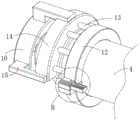
FIG. 5 is an enlarged view of B of FIG. 4 in accordance with the present invention;
FIG. 6 is a cross-sectional view of the drain pipe of the present invention;
fig. 7 is another view of fig. 6 illustrating the present invention.
In the figure: 1 vertical shaft, 2 communicating pipe, 3U-shaped pipe, 4 discharge pipe, 5 bracket, 6 bearing plate, 7 air pump, 8 infrared sensor, 9 trachea, 10 servo motor, 11 sealing disk, 12 upper fixed ring, 13 fixed column, 14 first water blocking semicircle ring, 15 mount, 16 second water blocking semicircle ring, 17 reinforcing bulge loop, 18 reinforcing groove ring, 19 dispersion cone column, 20 lower fixed ring, 21 lower bump, 22 upper bump, 23 limiting groove, 24 groove frame, 25 frame body, 26 directional rod, 27 fixed spring, 28 directional L-shaped block, 29 fixed block, 30 guide cylinder, 31 buffer spring, 32 guide column.
Detailed Description
Embodiments of the present invention will be further described with reference to the accompanying drawings.
Example 1:
as shown in fig. 1-7, a deep system drainage structure comprises a plurality of groups of vertical shafts 1, two adjacent groups of vertical shafts 1 are fixedly communicated with each other, a communicating pipe 2 is positioned at the lower part of the vertical shaft 1, a U-shaped pipe 3 is fixedly arranged on the inner wall of the vertical shaft 1 and positioned at the edge, one end of the U-shaped pipe 3 is positioned in the vertical shaft 1, the other end of the U-shaped pipe 3 is positioned at the outer side of the vertical shaft 1, the U-shaped pipe 3 is positioned at one end of the vertical shaft 1 at the same vertical line and is higher than one end at the outer side, a pressurizing part is arranged in the U-shaped pipe 3 and positioned on the outer side wall of the vertical shaft 1, a discharge pipe 4 extends at the other end of the U-shaped pipe 3, a fixing part is arranged at the outer side of the discharge pipe 4, a dispersing part extends on the side face of the fixing part, and the axle center of the dispersing part and the axle center of the discharge pipe 4 are positioned on the same horizontal line. Through adopting above-mentioned drainage structure, it can realize the inside evacuation of pipeline with the help of the pressure boost piece, and then guaranteed to realize automatic drainage through the siphon, can rivers play fine buffering through adopting the dispersing piece.
Further, the supercharging piece is including extending the bearing plate 6 on the lateral wall upper portion of shaft 1, the lower terminal surface of bearing plate 6 extends there is bracket 5, the up end fixed mounting of bearing plate 6 has air pump 7, the up end fixed mounting of bracket 5 has servo motor 10, the tip of air pump 7 extends there is trachea 9, the tip of trachea 9 runs through and inlays in the surface of U-shaped pipe 3, the top of the surface trachea 9 of U-shaped pipe 3 runs through and inlays there is infrared sensor 8, the controller is installed to infrared sensor 8's tip. The air pump 7 and the servo motor 10 can be fixed through the arranged bearing plate 6 and bracket 5, the air pipe 9 plays a role in air guide, and the sealing disc 11 plays a role in sealing the U-shaped pipe 3.
Further, the output shaft of the servo motor 10 rotates to penetrate through and is embedded in the outer surface of the U-shaped pipe 3, the output shaft of the servo motor 10 extends to form a sealing disc 11, the outer surface of the sealing disc 11 is attached to the inner wall of the U-shaped pipe 3, a rubber ring extends to the outer surface of the sealing disc 11, and the servo motor 10 and the air pump 7 are connected with a controller. The tightness can be improved through the rubber ring, and the controller can control the servo motor 10 and the air pump 7.
Further, the fixing piece comprises a reinforcing convex ring 17 extending at the position, close to the edge, of the outer surface of the discharge pipe 4, an upper fixing ring 12 and a lower fixing ring 20 are mounted at the position, close to the edge, of the outer surface of the discharge pipe 4 in a fitting mode, the reinforcing convex ring 17 respectively penetrates through the inner portion of the lower fixing ring 20 and the inner portion of the upper fixing ring 12 in a sliding mode, the lower end face of the upper fixing ring 12 is pressed on the upper end face of the lower fixing ring 20, an upper protruding block 22 extends at the edge of the outer surface of the upper fixing ring 12, a lower protruding block 21 extends at the edge of the outer surface of the lower fixing ring 20, and the lower end face of the upper protruding block 22 is attached to the upper end face of the lower protruding block 21. The upper and lower fixing rings 12 and 20 can be reinforced by the reinforcing convex rings 17, and the upper and lower protrusions 22 and 21 serve to fix the upper and lower fixing rings 12 and 20 together.
Further, the middle part of the upper end surface of the lower protruding block 21 extends to form a fixed block 29, the fixed block 29 is slidably inserted into the upper protruding block 22, two groups of limiting grooves 23 are respectively formed in the front end surface and the rear end surface of the fixed block 29, a groove frame 24 is mounted in the limiting grooves 23 in a fit manner, the groove frame 24 is tightly pressed on the upper end surface of the upper protruding block 22, an oriented L-shaped block 28 is extended on the side surface of the groove frame 24, a frame 25 is extended on the side surface of the upper protruding block 22, an oriented rod 26 is extended at the inner center position of the frame 25, the oriented rod 26 is slidably inserted into the oriented L-shaped block 28, a fixed spring 27 is wound on the outer side of the oriented rod 26, and the fixed spring 27 is located between the inner side surface of the frame 25 and the side surface of the oriented L-shaped block 28. The upper protruding block 22 and the lower protruding block 21 can be fixed together through the cooperation between the fixed block 29 and the groove frame 24, the limiting groove 23 can limit the groove frame 24, the fixed spring 27 can fix the groove frame 24, and the directional rod 26 and the directional L-shaped block 28 play a guiding role.
Further, the dispersing piece comprises a fixing column 13 extending on the side face of the upper fixing ring 12, a first water blocking semicircular ring 14 extends at the end portion of the fixing column 13, the inner outer surface of the first water blocking semicircular ring 14 is attached to the outer surface of the discharge pipe 4, a plurality of groups of fixing frames 15 extend on the outer surface of the first water blocking semicircular ring 14, a second water blocking semicircular ring 16 is inlaid at the end portion of each of the fixing frames 15, the axial lead of the second water blocking semicircular ring 16 and the axial lead of the first water blocking semicircular ring 14 are located on the same horizontal line, a reinforcing groove ring 18 extends at the edge of the outer surface of the discharge pipe 4, and the first water blocking semicircular ring 14 is attached to the inner outer surface of the reinforcing groove ring 18 in a sliding mode. The upper fixing ring 12 and the first water-blocking semicircular ring 14 can be fixed together through the fixing columns 13, the first water-blocking semicircular ring 14 can be reinforced through the reinforcing groove ring 18, and the first water-blocking semicircular ring 14 and the second water-blocking semicircular ring 16 can be fixed together through the fixing frames 15.
Further, the side of the second water-blocking semicircular ring 16 is coaxially penetrated and inlaid with a guide cylinder 30, a guide column 32 is mounted in the guide cylinder 30 in a fitting and sliding manner, a dispersing cone column 19 is coaxially extended at the end part of the guide column 32, a buffer spring 31 is wound on the outer side of the guide column 32, the buffer spring 31 is located between the side of the dispersing cone column 19 and the side of the guide cylinder 30, and the inner edge of the second water-blocking semicircular ring 16 and the inner edge of the first water-blocking semicircular ring 14 are both in an arc shape. The dispersion cone 19 can be oriented by the cooperation of the guide column 32 and the guide cylinder 30, the dispersion cone 19 can disperse the water, and the buffer spring 31 can buffer the impact force of the water when the water impacts on the dispersion cone 19.
Further, the inner wall of the vertical shaft 1 is extended with a connecting block, the end part of the connecting block is fixedly connected with the outer surface of the U-shaped pipe 3, the U-shaped pipe 3 and the discharge pipe 4 are integrally formed, and the axial lead of the dispersion cone column 19 and the axial lead of the discharge pipe 4 are positioned on the same horizontal line. The U-shaped pipe 3 and the shaft 1 can be fixed together by the connecting block provided.
Example 2:
the application method of the profound system drainage structure comprises the following steps:
step one: the user places the upper and lower fixing rings 12 and 20 on the discharge pipe 4 and closes the same, when the discharge pipe 4 is positioned between the lower and upper fixing rings 20 and 12, the fixing block 29 on the lower projection 21 passes through the inside of the upper projection 22, then the directional L-shaped block 28 slides on the directional rod 26 in the frame 25 under the pushing of the fixing spring 27, and then the slot frame 24 is driven to move, so that the slot frame 24 can slide into the limiting slot 23 on the fixing block 29, the fixing block 29 is fixed in the upper projection 22, the lower projection 21 and the upper projection 22 can be fixed together, and then the upper and lower fixing rings 12 and 20 are fixed together, so that the dispersing pieces on the upper fixing ring 12 can be fixed on the discharge pipe 4;
step two: when a large amount of water is stored in the vertical shaft 1, the servo motor 10 can be driven to drive the sealing disc 11 to rotate in the U-shaped pipe 3 through the servo motor 10, the U-shaped pipe 3 is sealed through the sealing disc 11, then the air pump 7 works to pump out the air in the U-shaped pipe 3 through the air pipe 9, so that the interior of the U-shaped pipe 3 is pressurized to suck the water in the vertical shaft 1 into the U-shaped pipe 3;
step three: when water in the U-shaped pipe 3 flows to the infrared sensor 8, the infrared sensor 8 sends a signal when sensing the water passing through to be transmitted to the controller, so that the controller sends a signal to stop the operation of the air pump 7, and the servo motor 10 works to drive the sealing disc 11 to reset so as to open the U-shaped pipe 3, so that the water sucked into the U-shaped pipe 3 flows downwards under the action of gravity and is discharged through the discharge pipe 4, and a siphon effect is generated to achieve the effect of continuous water discharge;
step four: the water discharged from the discharge pipe 4 is impacted on the dispersion cone column 19, so that the water is dispersed upwards under the action of the conical surface of the dispersion cone column 19, the water at the lower part after dispersion falls into the reservoir under the action of self weight, the water at the upper part is impacted on the second water-blocking semicircular ring 16, so that part of the water falls into the reservoir under the blocking of the second water-blocking semicircular ring 16, and the other part of the water impacted on the second water-blocking semicircular ring 16 is guided under the action of the circular arc shape in the second water-blocking semicircular ring 16 and then impacted in the first water-blocking semicircular ring 14, so that the water falls into the reservoir under the blocking of the first water-blocking semicircular ring 14 for discharge.
Claims (3)
1. A profound system drainage structure, characterized in that: the vertical shaft type hydraulic pressure dispersing device comprises a plurality of groups of vertical shafts (1), communicating pipes (2) are fixedly communicated between two adjacent groups of vertical shafts (1), the communicating pipes (2) are located at the lower part of the vertical shafts (1), U-shaped pipes (3) are fixedly arranged on the inner wall of the vertical shafts (1) located at the edge, one ends of the U-shaped pipes (3) are located in the vertical shafts (1), the other ends of the U-shaped pipes (3) are located at the outer side of the vertical shafts (1), the height of one end of the U-shaped pipes (3) located in the vertical shafts (1) is higher than that of one end outside, a pressurizing part is arranged in the U-shaped pipes (3) and located on the outer side wall of the vertical shafts (1), fixing parts are arranged at the outer sides of the U-shaped pipes (3), dispersing parts extend on the side faces of the fixing parts, and the axle centers of the dispersing parts and the axle centers of the discharging pipes (4) are located on the same horizontal line.
The supercharging piece comprises a bearing plate (6) extending to the upper portion of the outer side wall of the vertical shaft (1), a bracket (5) extends to the lower end face of the bearing plate (6), an air pump (7) is fixedly installed on the upper end face of the bearing plate (6), a servo motor (10) is fixedly installed on the upper end face of the bracket (5), an air pipe (9) extends to the end portion of the air pump (7), the end portion of the air pipe (9) penetrates through and is inlaid on the outer surface of the U-shaped pipe (3), an infrared sensor (8) penetrates through and is inlaid above the air pipe (9) on the outer surface of the U-shaped pipe (3), and a controller is installed at the end portion of the infrared sensor (8);
the output shaft of the servo motor (10) rotates to penetrate through the outer surface of the U-shaped pipe (3), the output shaft of the servo motor (10) extends to form a sealing disc (11), the outer surface of the sealing disc (11) is attached to the inner wall of the U-shaped pipe (3), a rubber ring extends to the outer surface of the sealing disc (11), and the servo motor (10) and the air pump (7) are connected with a controller;
the fixing piece comprises a reinforcing convex ring (17) which extends to the position, close to the edge, of the outer surface of the discharge pipe (4), an upper fixed ring (12) and a lower fixed ring (20) are mounted on the position, close to the edge, of the outer surface of the discharge pipe (4), the reinforcing convex ring (17) respectively penetrates through the inner part of the lower fixed ring (20) and the inner part of the upper fixed ring (12) in a sliding mode, the lower end face of the upper fixed ring (12) is tightly pressed on the upper end face of the lower fixed ring (20), an upper protruding block (22) extends to the edge of the outer surface of the upper fixed ring (12), a lower protruding block (21) extends to the edge of the outer surface of the lower fixed ring (20), and the lower end face of the upper protruding block (22) is attached to the upper end face of the lower protruding block (21);
the middle part of the upper end face of the lower protruding block (21) is extended with a fixed block (29), the fixed block (29) is penetrated into the upper protruding block (22) in a sliding way, two groups of limiting grooves (23) are respectively formed in the front end face and the rear end face of the fixed block (29), a groove frame (24) is mounted in the limiting grooves (23) in a fitting way, the groove frame (24) is tightly pressed on the upper end face of the upper protruding block (22), the side face of the groove frame (24) is extended with an oriented L-shaped block (28), the side face of the upper protruding block (22) is extended with a frame body (25), the inner center position of the frame body (25) is extended with an oriented rod (26), the oriented rod (26) is penetrated into the inside of the oriented L-shaped block (28) in a sliding way, a fixed spring (27) is wound on the outer side of the oriented rod (26), and the fixed spring (27) is positioned between the inner side face of the frame body (25) and the side face of the oriented L-shaped block (28);
the dispersing piece comprises fixing columns (13) extending on the side face of the upper fixing ring (12), a first water-blocking semicircular ring (14) extends at the end of each fixing column (13), the inner outer surface of each first water-blocking semicircular ring (14) is attached to the outer surface of the corresponding discharge pipe (4), a plurality of groups of fixing frames (15) extend on the outer surface of each first water-blocking semicircular ring (14), a second water-blocking semicircular ring (16) is inlaid at the end of each plurality of groups of fixing frames (15), the axial leads of the second water-blocking semicircular rings (16) and the axial leads of the first water-blocking semicircular rings (14) are located on the same horizontal line, a reinforcing groove ring (18) extends at the edge of the outer surface of each discharge pipe (4), and each first water-blocking semicircular ring (14) is slidably attached to the inner outer surface of the corresponding reinforcing groove ring (18);
the side of semicircle ring that blocks water of No. two (16) is coaxial to be run through and is inlayed there is guide cylinder (30), the inside laminating slidable mounting of guide cylinder (30) has guide post (32), the tip coaxial extension of guide post (32) has dispersion awl post (19), the outside winding of guide post (32) has buffer spring (31), buffer spring (31) are located between the side of dispersion awl post (19) and the side of guide cylinder (30), the inside edge department of semicircle ring that blocks water of No. two (16) and the inside edge department of semicircle ring that blocks water of No. one (14) are all offered to circular-arc.
2. A deep system drain structure according to claim 1, wherein: the inner wall of shaft (1) extends there is the connecting block, the tip and the surface fixed connection of U-shaped pipe (3) of connecting block, U-shaped pipe (3) and exhaust pipe (4) integrated into one piece, the axial lead of dispersion awl post (19) and the axial lead of exhaust pipe (4) are located same horizontal line.
3. A method of using the deep water drainage structure of any one of claims 1-2, comprising the steps of:
step one: the user places the upper fixed ring (12) and the lower fixed ring (20) on the discharge pipe (4) and closes the discharge pipe (4), at this time, the discharge pipe (4) is positioned between the lower fixed ring (20) and the upper fixed ring (12), a fixed block (29) on the lower convex block (21) passes through the inside of the upper convex block (22), then the directional L-shaped block (28) slides on a directional rod (26) in the frame body (25) under the pushing of a fixed spring (27), and then the groove frame (24) is driven to move, so that the groove frame (24) can slide into a limiting groove (23) on the fixed block (29), so that the fixed block (29) is fixed in the upper convex block (22), the lower convex block (21) and the upper convex block (22) can be fixed together, and then the upper fixed ring (12) and the lower fixed ring (20) can be fixed together, and a dispersing piece on the upper fixed ring (12) can be fixed on the discharge pipe (4);
step two: when a large amount of water is stored in the vertical shaft (1), the servo motor (10) can be driven to drive the sealing disc (11) to rotate in the U-shaped pipe (3) through the servo motor (10), the U-shaped pipe (3) is sealed through the sealing disc (11), then the air pump (7) works to pump out the air in the U-shaped pipe (3) through the air pipe (9), and the interior of the U-shaped pipe (3) is pressurized to suck the water in the vertical shaft (1) into the U-shaped pipe (3);
step three: when water in the U-shaped pipe (3) flows to the position of the infrared sensor (8), the infrared sensor (8) sends a signal when sensing the water flowing through the U-shaped pipe to transmit the signal to the controller, so that the air pump (7) of the U-shaped pipe stops working, the servo motor (10) works to drive the sealing disc (11) to reset so as to open the U-shaped pipe (3), and the water sucked into the U-shaped pipe (3) flows through the discharge pipe (4) to be discharged under the action of gravity, so that a siphon effect is generated to achieve the effect of continuous water discharge;
step four: the water discharged from the discharge pipe (4) can collide on the dispersion cone column (19), so that the water is dispersed upwards under the action of the conical surface of the dispersion cone column (19), the water at the lower part after dispersion can fall into the reservoir under the action of self weight, the water at the upper part can collide on the second water-blocking semicircular ring (16), part of the water falls into the reservoir under the blocking of the second water-blocking semicircular ring (16), and the other part of the water colliding on the second water-blocking semicircular ring (16) can be guided under the action of the circular arc in the second water-blocking semicircular ring (16) so as to collide in the first water-blocking semicircular ring (14), so that the water falls into the reservoir under the blocking of the first water-blocking semicircular ring (14) to be discharged.
Priority Applications (1)
| Application Number | Priority Date | Filing Date | Title |
|---|---|---|---|
| CN202110938488.2A CN113684906B (en) | 2021-08-16 | 2021-08-16 | Profound system drainage structure and use method |
Applications Claiming Priority (1)
| Application Number | Priority Date | Filing Date | Title |
|---|---|---|---|
| CN202110938488.2A CN113684906B (en) | 2021-08-16 | 2021-08-16 | Profound system drainage structure and use method |
Publications (2)
| Publication Number | Publication Date |
|---|---|
| CN113684906A CN113684906A (en) | 2021-11-23 |
| CN113684906B true CN113684906B (en) | 2023-05-02 |
Family
ID=78580094
Family Applications (1)
| Application Number | Title | Priority Date | Filing Date |
|---|---|---|---|
| CN202110938488.2A Active CN113684906B (en) | 2021-08-16 | 2021-08-16 | Profound system drainage structure and use method |
Country Status (1)
| Country | Link |
|---|---|
| CN (1) | CN113684906B (en) |
Family Cites Families (8)
| Publication number | Priority date | Publication date | Assignee | Title |
|---|---|---|---|---|
| DE3670520D1 (en) * | 1985-05-25 | 1990-05-23 | Vollmar Oskar Gmbh | SYSTEM FOR CONTROLLING THE WATER DRAINAGE FROM A RAIN BASIN OR A DUCT PIPE. |
| CN2219978Y (en) * | 1995-03-08 | 1996-02-14 | 哈尔滨鹭滨工业电子有限公司 | a siphon tank |
| CN102720266A (en) * | 2012-06-18 | 2012-10-10 | 上海市城市建设设计研究总院 | Siphon type dredging device for water storage and drainage tunnel |
| CN204457860U (en) * | 2015-02-06 | 2015-07-08 | 山东唐口煤业有限公司 | Mine zero power siphon drainage device |
| CN210764388U (en) * | 2019-08-16 | 2020-06-16 | 山西太钢碧水源环保科技有限公司 | Water supply and drainage device of sewage treatment tank |
| CN112459700A (en) * | 2020-11-07 | 2021-03-09 | 刘圣建 | Well-digging and well-washing integrated equipment for building construction |
| CN113187086A (en) * | 2021-03-29 | 2021-07-30 | 唐友慧 | Siphon type sewage treatment emptying device |
| CN216108884U (en) * | 2021-08-16 | 2022-03-22 | 长江生态环保集团有限公司 | Profound system drainage structure |
-
2021
- 2021-08-16 CN CN202110938488.2A patent/CN113684906B/en active Active
Also Published As
| Publication number | Publication date |
|---|---|
| CN113684906A (en) | 2021-11-23 |
Similar Documents
| Publication | Publication Date | Title |
|---|---|---|
| CN102966090B (en) | System for automatically draining water on side slope and method therefor | |
| CN216108884U (en) | Profound system drainage structure | |
| CN104234735B (en) | A kind of adjustable for height lift surface wind mouth structure | |
| CN116679354A (en) | Automatic monitoring device for meteorological detection environment protection | |
| CN202989903U (en) | Automatic side slope drainage system | |
| CN213296399U (en) | Civil engineering drainage structure | |
| CN112012913B (en) | Oil-well pump for oil field | |
| CN112482397A (en) | Can carry out building foundation ditch supporting device who improves to construction environment | |
| CN215629741U (en) | Hydraulic engineering bank protection device | |
| CN113684906A (en) | Deep system drainage structure and using method | |
| CN109853663B (en) | Full-automatic water supply and drainage system for buildings | |
| CN112359676A (en) | Town road drainage structures with prevent function of flowing backwards | |
| CN110454347A (en) | Kinetic energy recovery device and drainage system | |
| CN113047391B (en) | A drainage device for improving easy ponding road security | |
| CN213061813U (en) | Full-automatic hydraulic lifting column road pile | |
| CN213625946U (en) | Drainage device for constructional engineering | |
| CN115748703A (en) | A punching pile driver for rapidly breaking hard rock formations and its punching method | |
| CN211142953U (en) | Environment-friendly watering device for municipal works | |
| CN216041016U (en) | Life-prolonging elastic sealing type water gate structure | |
| CN208105376U (en) | A kind of assembled irrigation pumping station | |
| CN215105844U (en) | Rain and sewage flow divider for buildings | |
| CN220415454U (en) | Automatic drainage device of air pump | |
| CN219176035U (en) | Building safety device | |
| CN219825202U (en) | A kind of strong drainage pipe type strong drainage preloading device for foundation engineering | |
| CN219138173U (en) | Building roof cornice waterproof construction |
Legal Events
| Date | Code | Title | Description |
|---|---|---|---|
| PB01 | Publication | ||
| PB01 | Publication | ||
| SE01 | Entry into force of request for substantive examination | ||
| SE01 | Entry into force of request for substantive examination | ||
| GR01 | Patent grant | ||
| GR01 | Patent grant |