CN113683045B - Multistation blows embedment equipment - Google Patents
Multistation blows embedment equipment Download PDFInfo
- Publication number
- CN113683045B CN113683045B CN202111132142.XA CN202111132142A CN113683045B CN 113683045 B CN113683045 B CN 113683045B CN 202111132142 A CN202111132142 A CN 202111132142A CN 113683045 B CN113683045 B CN 113683045B
- Authority
- CN
- China
- Prior art keywords
- die
- assembly
- filling
- ampoule
- adjusting
- Prior art date
- Legal status (The legal status is an assumption and is not a legal conclusion. Google has not performed a legal analysis and makes no representation as to the accuracy of the status listed.)
- Active
Links
- 239000003708 ampul Substances 0.000 claims abstract description 155
- 238000011049 filling Methods 0.000 claims abstract description 139
- 239000000084 colloidal system Substances 0.000 claims abstract description 65
- 238000000465 moulding Methods 0.000 claims abstract description 51
- 230000007246 mechanism Effects 0.000 claims abstract description 50
- 238000007789 sealing Methods 0.000 claims abstract description 49
- 239000007788 liquid Substances 0.000 claims abstract description 34
- 239000003814 drug Substances 0.000 claims abstract description 28
- 238000007664 blowing Methods 0.000 claims abstract description 25
- 238000012856 packing Methods 0.000 claims abstract description 25
- 238000009826 distribution Methods 0.000 claims abstract description 20
- 239000000155 melt Substances 0.000 claims abstract description 18
- 238000005538 encapsulation Methods 0.000 claims abstract description 14
- 238000001125 extrusion Methods 0.000 claims description 87
- 239000003292 glue Substances 0.000 claims description 55
- 238000007493 shaping process Methods 0.000 claims description 21
- 230000001105 regulatory effect Effects 0.000 claims description 20
- 230000001360 synchronised effect Effects 0.000 claims description 20
- 238000003825 pressing Methods 0.000 claims description 18
- 230000005540 biological transmission Effects 0.000 claims description 10
- 238000000071 blow moulding Methods 0.000 claims description 9
- 230000001276 controlling effect Effects 0.000 claims description 8
- 230000008859 change Effects 0.000 claims description 3
- 238000012958 reprocessing Methods 0.000 claims description 2
- 238000004382 potting Methods 0.000 claims 4
- 238000004519 manufacturing process Methods 0.000 description 28
- QVGXLLKOCUKJST-UHFFFAOYSA-N atomic oxygen Chemical compound [O] QVGXLLKOCUKJST-UHFFFAOYSA-N 0.000 description 26
- 239000001301 oxygen Substances 0.000 description 26
- 229910052760 oxygen Inorganic materials 0.000 description 26
- IJGRMHOSHXDMSA-UHFFFAOYSA-N Atomic nitrogen Chemical compound N#N IJGRMHOSHXDMSA-UHFFFAOYSA-N 0.000 description 18
- 238000001514 detection method Methods 0.000 description 18
- 150000001875 compounds Chemical class 0.000 description 15
- 239000004033 plastic Substances 0.000 description 13
- 229920003023 plastic Polymers 0.000 description 13
- 239000007789 gas Substances 0.000 description 12
- 230000002457 bidirectional effect Effects 0.000 description 10
- 229910052757 nitrogen Inorganic materials 0.000 description 9
- 230000009471 action Effects 0.000 description 7
- 230000000694 effects Effects 0.000 description 6
- 238000012371 Aseptic Filling Methods 0.000 description 4
- 238000010586 diagram Methods 0.000 description 4
- 230000004048 modification Effects 0.000 description 4
- 238000012986 modification Methods 0.000 description 4
- 239000007921 spray Substances 0.000 description 4
- 230000005484 gravity Effects 0.000 description 3
- 238000010438 heat treatment Methods 0.000 description 3
- 239000012943 hotmelt Substances 0.000 description 3
- 230000000149 penetrating effect Effects 0.000 description 3
- 238000001816 cooling Methods 0.000 description 2
- 125000004122 cyclic group Chemical group 0.000 description 2
- 238000007599 discharging Methods 0.000 description 2
- 238000005265 energy consumption Methods 0.000 description 2
- 239000011261 inert gas Substances 0.000 description 2
- 238000001746 injection moulding Methods 0.000 description 2
- 238000000034 method Methods 0.000 description 2
- 238000012544 monitoring process Methods 0.000 description 2
- 239000000843 powder Substances 0.000 description 2
- 230000008569 process Effects 0.000 description 2
- 238000012545 processing Methods 0.000 description 2
- 238000009751 slip forming Methods 0.000 description 2
- 238000001179 sorption measurement Methods 0.000 description 2
- 238000012546 transfer Methods 0.000 description 2
- 230000009286 beneficial effect Effects 0.000 description 1
- 230000036760 body temperature Effects 0.000 description 1
- 238000003763 carbonization Methods 0.000 description 1
- 239000012141 concentrate Substances 0.000 description 1
- 230000008602 contraction Effects 0.000 description 1
- 230000007547 defect Effects 0.000 description 1
- 239000012467 final product Substances 0.000 description 1
- 230000006872 improvement Effects 0.000 description 1
- 238000009434 installation Methods 0.000 description 1
- 230000010354 integration Effects 0.000 description 1
- 238000012423 maintenance Methods 0.000 description 1
- 238000002844 melting Methods 0.000 description 1
- 230000008018 melting Effects 0.000 description 1
- 238000004806 packaging method and process Methods 0.000 description 1
- 239000000047 product Substances 0.000 description 1
- 230000002035 prolonged effect Effects 0.000 description 1
- 238000012797 qualification Methods 0.000 description 1
- 239000002994 raw material Substances 0.000 description 1
- 239000000523 sample Substances 0.000 description 1
- 238000011064 split stream procedure Methods 0.000 description 1
- 230000007480 spreading Effects 0.000 description 1
- 238000003892 spreading Methods 0.000 description 1
- 238000007666 vacuum forming Methods 0.000 description 1
Images


Classifications
-
- B—PERFORMING OPERATIONS; TRANSPORTING
- B67—OPENING, CLOSING OR CLEANING BOTTLES, JARS OR SIMILAR CONTAINERS; LIQUID HANDLING
- B67C—CLEANING, FILLING WITH LIQUIDS OR SEMILIQUIDS, OR EMPTYING, OF BOTTLES, JARS, CANS, CASKS, BARRELS, OR SIMILAR CONTAINERS, NOT OTHERWISE PROVIDED FOR; FUNNELS
- B67C7/00—Concurrent cleaning, filling, and closing of bottles; Processes or devices for at least two of these operations
- B67C7/0073—Sterilising, aseptic filling and closing
-
- B—PERFORMING OPERATIONS; TRANSPORTING
- B65—CONVEYING; PACKING; STORING; HANDLING THIN OR FILAMENTARY MATERIAL
- B65B—MACHINES, APPARATUS OR DEVICES FOR, OR METHODS OF, PACKAGING ARTICLES OR MATERIALS; UNPACKING
- B65B3/00—Packaging plastic material, semiliquids, liquids or mixed solids and liquids, in individual containers or receptacles, e.g. bags, sacks, boxes, cartons, cans, or jars
- B65B3/003—Filling medical containers such as ampoules, vials, syringes or the like
-
- B—PERFORMING OPERATIONS; TRANSPORTING
- B67—OPENING, CLOSING OR CLEANING BOTTLES, JARS OR SIMILAR CONTAINERS; LIQUID HANDLING
- B67C—CLEANING, FILLING WITH LIQUIDS OR SEMILIQUIDS, OR EMPTYING, OF BOTTLES, JARS, CANS, CASKS, BARRELS, OR SIMILAR CONTAINERS, NOT OTHERWISE PROVIDED FOR; FUNNELS
- B67C3/00—Bottling liquids or semiliquids; Filling jars or cans with liquids or semiliquids using bottling or like apparatus; Filling casks or barrels with liquids or semiliquids
- B67C3/02—Bottling liquids or semiliquids; Filling jars or cans with liquids or semiliquids using bottling or like apparatus
- B67C3/22—Details
- B67C3/26—Filling-heads; Means for engaging filling-heads with bottle necks
-
- B—PERFORMING OPERATIONS; TRANSPORTING
- B67—OPENING, CLOSING OR CLEANING BOTTLES, JARS OR SIMILAR CONTAINERS; LIQUID HANDLING
- B67C—CLEANING, FILLING WITH LIQUIDS OR SEMILIQUIDS, OR EMPTYING, OF BOTTLES, JARS, CANS, CASKS, BARRELS, OR SIMILAR CONTAINERS, NOT OTHERWISE PROVIDED FOR; FUNNELS
- B67C3/00—Bottling liquids or semiliquids; Filling jars or cans with liquids or semiliquids using bottling or like apparatus; Filling casks or barrels with liquids or semiliquids
- B67C3/02—Bottling liquids or semiliquids; Filling jars or cans with liquids or semiliquids using bottling or like apparatus
- B67C3/22—Details
- B67C2003/227—Additional apparatus related to blow-moulding of the containers, e.g. a complete production line forming filled containers from preforms
-
- B—PERFORMING OPERATIONS; TRANSPORTING
- B67—OPENING, CLOSING OR CLEANING BOTTLES, JARS OR SIMILAR CONTAINERS; LIQUID HANDLING
- B67C—CLEANING, FILLING WITH LIQUIDS OR SEMILIQUIDS, OR EMPTYING, OF BOTTLES, JARS, CANS, CASKS, BARRELS, OR SIMILAR CONTAINERS, NOT OTHERWISE PROVIDED FOR; FUNNELS
- B67C7/00—Concurrent cleaning, filling, and closing of bottles; Processes or devices for at least two of these operations
- B67C7/0006—Conveying; Synchronising
- B67C2007/006—Devices particularly adapted for container filling
-
- B—PERFORMING OPERATIONS; TRANSPORTING
- B67—OPENING, CLOSING OR CLEANING BOTTLES, JARS OR SIMILAR CONTAINERS; LIQUID HANDLING
- B67C—CLEANING, FILLING WITH LIQUIDS OR SEMILIQUIDS, OR EMPTYING, OF BOTTLES, JARS, CANS, CASKS, BARRELS, OR SIMILAR CONTAINERS, NOT OTHERWISE PROVIDED FOR; FUNNELS
- B67C7/00—Concurrent cleaning, filling, and closing of bottles; Processes or devices for at least two of these operations
- B67C7/0006—Conveying; Synchronising
- B67C2007/0066—Devices particularly adapted for container closing
-
- Y—GENERAL TAGGING OF NEW TECHNOLOGICAL DEVELOPMENTS; GENERAL TAGGING OF CROSS-SECTIONAL TECHNOLOGIES SPANNING OVER SEVERAL SECTIONS OF THE IPC; TECHNICAL SUBJECTS COVERED BY FORMER USPC CROSS-REFERENCE ART COLLECTIONS [XRACs] AND DIGESTS
- Y02—TECHNOLOGIES OR APPLICATIONS FOR MITIGATION OR ADAPTATION AGAINST CLIMATE CHANGE
- Y02P—CLIMATE CHANGE MITIGATION TECHNOLOGIES IN THE PRODUCTION OR PROCESSING OF GOODS
- Y02P70/00—Climate change mitigation technologies in the production process for final industrial or consumer products
- Y02P70/10—Greenhouse gas [GHG] capture, material saving, heat recovery or other energy efficient measures, e.g. motor control, characterised by manufacturing processes, e.g. for rolling metal or metal working
Landscapes
- Engineering & Computer Science (AREA)
- Mechanical Engineering (AREA)
- Basic Packing Technique (AREA)
- Blow-Moulding Or Thermoforming Of Plastics Or The Like (AREA)
Abstract
The invention discloses a multi-station blowing and filling and sealing device, which comprises: an extruder for transporting the molten colloid; the melt distribution mechanism is used for connecting the extruder and the multi-group molding encapsulation system; the molding and filling and sealing system is at least provided with 2 groups, and is in linear arrangement and used for forming the ampoule bottles by the packing elements, and is used for filling and sealing the liquid medicine of the ampoule bottles, so that filling and sealing work of the ampoule bottles is realized at a plurality of stations simultaneously, and the capacity of the ampoule bottles is improved.
Description
Technical Field
The invention relates to the technical field of ampoule bottle filling, in particular to multi-station blowing and filling equipment.
Background
Blow Fill and Seal (BFS) aseptic filling process is a known process for producing aseptic products that are filled and sealed in bottles. The aseptic filling production process of blowing, filling and sealing (BFS) generally comprises the steps of heating and melting a plastic blank, extruding the blank, opening and closing a main die, intercepting the plastic blank, blowing or vacuum forming the plastic blank, quantitatively filling the content into a bottle, sealing a bottle head, discharging the bottle and the like. Because the aseptic filling production process of blowing, filling and sealing (BFS) can furthest ensure that the content is prevented from being polluted by the external environment, the aseptic filling production process is widely concerned, and particularly has very important application in the pharmaceutical industry with the aseptic requirement on the final product.
When the existing blowing and filling and sealing equipment is used for production, only a single station can be used, and the productivity is too low to meet the existing market demands.
Aiming at the defects in the prior art, the invention provides multi-station blowing and filling and sealing equipment.
Disclosure of Invention
The invention provides multi-station blowing and filling and sealing equipment, which aims to solve the technical problems that the existing blowing and filling and sealing equipment can only work at a single station when being used for production, and the productivity is too low to meet the existing market demand.
According to one aspect of the present invention, there is provided a multi-station blow molding apparatus comprising:
an extruder for transporting the molten colloid;
the melt distribution mechanism is used for connecting the extruder and the multi-group molding encapsulation system;
the molding and encapsulating system is at least provided with 2 groups, and is in linear arrangement and used for molding the rubber cylinder to prepare the ampoule bottle, and is used for filling and sealing the liquid medicine of the ampoule bottle.
By adopting the technical scheme, the extruder heats the existing plastic raw materials to a molten state, the melt distribution mechanism at the outlet end of the extruder is connected with a plurality of molding encapsulation systems to work, colloid output by the extruder is split by the melt distribution mechanism, and colloid flow entering the molding encapsulation systems is controlled under the action of the melt distribution mechanism, so that colloid transmission flow in the molding encapsulation systems is consistent, the qualification rate of ampoule bottles is improved when the ampoule bottles are produced by the molding encapsulation systems at the same time, the ampoule bottle filling and sealing work is realized by the stations at the same time, the capacity of ampoule bottles is improved, and the molding encapsulation systems share one filling system; sharing a set of extrusion systems; the system has the effects of saving cost, reducing energy consumption and reducing occupied area.
Further, the molding filling and sealing system comprises a filling and sealing machine, an extrusion head and a molding die;
the filling and sealing machine is used for filling liquid medicine into the formed ampoule bottles;
the extrusion head is used for primarily forming the rubber cylinder for the rubber body and conveying the rubber cylinder;
the forming die is used for reprocessing the rubber cylinder, forming an ampoule bottle and sealing the ampoule bottle filled with the liquid medicine.
Through adopting above-mentioned technical scheme, when producing the ampoule, through extruding the first transmission packing element to forming die in, fill the powder charge liquid through the filling machine to the ampoule, move down and open the mould along with forming die with the ampoule that the filling is accomplished, through the body that moves up to packing element department and compound die accomplish the ampoule with forming die opening mould, fill the powder charge liquid to new ampoule through the filling machine again, open synchronous fixture and order about the clamping component to move up to the below of forming die through lifting unit and press from both sides the tail end to new ampoule, and then the embedment of ampoule is carried out to the cyclic operation, and the filling machine, extruding the first and the linear removal of forming die, work efficiency has been improved.
Further, the forming and filling systems are all arranged on the same plane.
Through adopting above-mentioned technical scheme, set up shaping filling system along the coplanar for a plurality of shaping filling systems evenly arrange at the output of extruder, have made things convenient for the installation of blowing filling and sealing equipment, and can concentrate the maintenance when blowing filling and sealing equipment damages.
Further, the forming and filling systems on the same extrusion head are arranged symmetrically left and right along the melt distribution mechanism.
By adopting the technical scheme, the molding and filling systems on the same blowing and filling equipment are symmetrically distributed along the two sides of the melt distribution mechanism, and the molding and filling systems are symmetrically distributed along the two sides of the melt distribution mechanism, so that the paths of the molding and filling systems of the colloid transmission channels are consistent by the melt distribution mechanism, and the problem that the molding and filling systems cannot synchronously feed glue for molding is avoided.
Further, the molding encapsulation systems on the same extrusion head are arranged in a left-right staggered manner along the melt distribution mechanism.
Through adopting above-mentioned technical scheme, when setting up a plurality of shaping filling systems, connect extruder and shaping filling system through melt distribution mechanism, stagger a plurality of shaping filling systems about along melt distribution mechanism and arrange, can save space position, make things convenient for multiunit shaping filling system evenly to arrange.
Further, the melt distribution mechanism includes:
the main pipe is connected with the extruder and is used for conveying colloid;
the branch system is arranged at the end part of the main pipe and is connected with at least two extrusion heads, and the branch system is used for adjusting the glue outlet amount of the main pipe conveying glue.
Through adopting above-mentioned technical scheme, through melt distribution mechanism with the interior molten state colloid of extruder along being responsible for through branch system transmission to a plurality of shaping filling systems, through connecting a plurality of shaping filling systems with the extruder and carrying out simultaneous working, improved the production efficiency of liquid medicine ampoule greatly, improved the productivity.
Further, still be provided with ampoule inner wall temperature detection mechanism on the extrusion head, ampoule inner wall temperature detection mechanism includes temperature detection subassembly, temperature detection subassembly is used for carrying out temperature detection to fashioned ampoule inner wall to be used for judging whether the ampoule that the shaping was accomplished satisfies the filling condition.
Through adopting above-mentioned technical scheme, when carrying out the temperature detection to the ampoule in the body mould, through stretching into the ampoule with the filling needle in, detect the inner wall temperature of ampoule through miniature temperature sensor, observe on transmitting the wireless temperature acquisition appearance with temperature numerical value, whether satisfy the inner wall temperature of ampoule and be less than 60 ℃ this condition and then carry out the filling of liquid medicine through judging, have and whether satisfy the effect that the filling temperature carries out real-time supervision to ampoule liquid medicine filling.
Further, still be provided with packing element thickness adjustment mechanism in the extrusion head, packing element thickness adjustment mechanism includes:
the adjusting component is arranged on the lower pressing plate and the die core plate, moves along the bottom of the lower pressing plate and is used for adjusting the size of a discharge hole of the die cavity;
the driving assembly is connected with the adjusting assembly and used for driving the adjusting assembly to move along the bottom of the lower pressing plate.
Through adopting above-mentioned technical scheme, when conveying the colloid in the extruder, form multiunit packing element through extrusion head with colloid transmission and control colloid wall and flow to forming die in, flow down along the die cavity between die core board and top board and the holding down plate through the colloid, through the wall thickness of regulating plate and guide block control packing element, control the wall thickness of packing element in the scope that satisfies the production demand, and then the clearance between fixed regulating plate assurance regulating plate and the guide block satisfies the wall thickness of packing element to realize the wall thickness regulation of packing element.
Further, the forming die comprises a head die and a body die, the head die is connected with the body die, a balance type die clamping mechanism is further arranged on the head die and the body die and used for stably driving the head die and the body die to be clamped.
Through adopting above-mentioned technical scheme, carry out extrusion through body mould to the body of ampoule, carry out extrusion through head mould to the bottle of ampoule, carry out the compound die respectively to head mould and body mould through balanced locking mechanism, carry out the compound die to body mould earlier and accomplish the body of ampoule, carry out filling liquid in to the ampoule through the liquid filling machine, the encapsulation of ampoule is accomplished to the compound die to head mould through balanced locking mechanism, has the effect that realizes embedment integration operation.
Further, the balanced clamping mechanism includes:
the pushing assembly is used for pushing the head die and the bottle body die to be matched;
and the balance component is used for being connected with the pushing component so that the pushing component can push the head die and the bottle body die to be matched.
Through adopting above-mentioned technical scheme, when will extruding the packing element in the head and flow to the forming die in, carry out the body of compound die shaping completion ampoule through the promotion of body template at first compound die hydro-cylinder, stretch into the filling needle to the ampoule body in carry out filling liquid medicine, drive the head template compound die through the second compound die hydro-cylinder and accomplish the bottle head shaping of ampoule, thereby accomplish the liquid medicine embedment of ampoule, and guaranteed forming die's stable compound die, and reduced the step distance of second compound die hydro-cylinder and reduced the energy consumption, the compound die stroke is short, improved the compound die precision, improved ampoule fashioned speed.
Further, the forming die bottom is provided with synchronous fixture, synchronous fixture is used for the stable shaping of ampoule, synchronous fixture includes:
the clamping assembly is arranged below the bottle body die and is used for clamping the ampoule bottle molded in the bottle body die;
a spreader assembly connected to the clamping assembly and adapted to open the clamping assembly for facilitating the molding of a cooled ampoule;
and the lifting assembly is connected with the clamping assembly and used for driving the clamping assembly to lift so as to repeatedly clamp the ampoule bottle molded by the bottle body die.
Through adopting above-mentioned technical scheme, when carrying out the centre gripping removal to the ampoule in the forming die, drive bi-directional threaded rod through step motor and rotate and drive the grip block and move the bottom of ampoule in opposite directions and press from both sides tightly, open forming die, ampoule and grip block that the filling is accomplished move down under lifting cylinder's effect, and the speed of moving down of grip block is unanimous with the speed that drops naturally of extruding first interior packing element, avoids the ampoule after the shaping to carry out the drop deformation to the packing element under the effect of gravity.
The invention has the following beneficial effects:
according to the multi-station blowing filling and sealing equipment, when liquid medicine filling of ampoule bottles is carried out, a plastic original is heated to a molten state through an extruder, a molten state colloid is transferred to a plurality of forming filling systems through an extruder, colloid is initially formed through the extruder, the flow rate of the colloid is controlled through a die cavity in the extruder, the colloid is naturally dropped into a discharge port of the extruder to form a rubber cylinder, the wall thickness of the rubber cylinder is controlled through an adjusting assembly according to production requirements, the rubber cylinder is transferred to a forming die, a moving template is pushed to move towards each other through a first die-closing cylinder to mold the body of the ampoule bottle, filling of the ampoule bottle is completed through filling of the filling and sealing template on the filling and sealing machine, the filling and sealing of the ampoule bottle is completed through a second die-closing cylinder, the ampoule bottle is clamped and moved through a synchronous clamping mechanism after filling and sealing of the ampoule bottle is completed, the ampoule bottle is driven to pass through the extruder and a filling needle on the extruder, the rubber cylinder is controlled to pass through the extruder and abut in the rubber cylinder according to production requirements, the servo push rod is driven to move the rubber cylinder, the filling and sealing needle is driven to move along with the extrusion and sealing needle, and the forming die is continuously carried out through the servo-pressing and the sealing die, and the forming efficiency is improved along with the forming die-closing and the sealing needle is continuously moved along with the moving the servo piston.
In addition to the objects, features and advantages described above, the present invention has other objects, features and advantages. The present invention will be described in further detail with reference to the drawings.
Drawings
The accompanying drawings, which are included to provide a further understanding of the invention and are incorporated in and constitute a part of this specification, illustrate embodiments of the invention and together with the description serve to explain the invention. In the drawings:
FIG. 1 is a schematic view of the overall structure of a preferred embodiment of the present invention;
FIG. 2 is a cross-sectional view of the extrusion head of FIG. 1 along a width direction axis;
FIG. 3 is a block diagram of the extrusion head of FIG. 1;
FIG. 4 is a block diagram of the forming die of FIG. 1;
FIG. 5 is a block diagram of the form-filling system of FIG. 1;
FIG. 6 is a schematic view of the structure of the blanking shunt of FIG. 2;
FIG. 7 is a central axis cross-sectional view of the main tube of FIG. 1;
FIG. 8 is a schematic view of a portion of the structure of FIG. 7;
FIG. 9 is a cross-sectional view of the main tube of FIG. 1 taken along the axis of the adjustment column;
FIG. 10 is a schematic diagram of the temperature sensing assembly of FIG. 2;
FIG. 11 is a schematic view of the oxygen concentration detection assembly of FIG. 2;
FIG. 12 is a schematic view of the gas delivery device of FIG. 11;
FIG. 13 is a schematic view of the synchronous clamping mechanism of FIG. 1;
Fig. 14 is a schematic structural view as a modification of the synchronous clamping mechanism in fig. 13;
fig. 15 is a side schematic view of the synchronous clamping mechanism of fig. 13.
Legend description:
1. an extruder; 11. a main pipe; 12. a branching system; 121. a branch pipe; 13. a regulatory component; 131. an adjusting column; 132. a thread groove; 133. a through hole; 134. a ball block; 135. a cylindrical block; 136. a buffer block; 2. an extrusion head; 21. a die holder; 211. an upper press plate; 212. a lower pressing plate; 213. a space plate; 214. a fastening assembly; 2141. a fastening screw; 215. a feeding seat; 22. a main flow tube; 23. a shunt assembly; 231. a primary flow dividing part; 2311. a U-shaped tube; 232. a secondary split stream section; 2321. a shunt; 24. a mold core assembly; 241. a core plate; 242. a buffer section; 2421. a first protrusion; 2422. a second protrusion; 243. a mold cavity; 25. a temperature detection assembly; 251. a miniature temperature sensor; 26. an adjustment assembly; 261. a first adjusting part; 2611. an adjusting plate; 2612. a guide plate; 2613. a guide block; 262. a second adjusting part; 2621. an adjusting block; 27. a drive assembly; 271. a first driving section; 2711. a first drive screw; 2712. an adjusting screw; 272. a second driving section; 2721. a second drive screw; 28. an oxygen concentration detection assembly; 281. an on-line oxygen detector; 282. a gas delivery device; 2821. a nitrogen cylinder; 2822. a filter; 2823. a gas pipe; 2824. a branch pipe; 29. a temperature control assembly; 291. a temperature control joint; 3. filling and sealing machine; 31. a filling needle; 4. a forming die; 41. a head mold; 411. a head template; 42. a bottle body mold; 423. a body template; 43. a pushing assembly; 431. a first pushing part; 4311. a first mold closing cylinder; 432. a second pushing part; 4321. a second mold closing cylinder; 44. a balancing assembly; 441. a pull rod; 45. fixing the template; 46. moving the template; 5. a synchronous clamping mechanism; 51. a clamping assembly; 511. a clamping plate; 512. a baffle; 52. a spreader assembly; 521. a lifting plate; 522. a two-way threaded rod; 523. a stepping motor; 53. a lifting assembly; 531. a lifting frame; 532. a lifting oil cylinder; 533. a level sensor; 54. a clamping part; 541. a first clamping plate; 542. a second clamping plate; 55. a spreader; 551. opening the cylinder; 552. a first distracting rack; 553. a second distracting rack; 554. a synchronizing gear; 555. a support frame; 56. a lifting part; 561. a lifting rod; 562. a driving wheel; 563. a conveyor belt; 564. a sliding plate; 565. a slide rail; 566. and driving the motor.
Detailed Description
Embodiments of the invention are described in detail below with reference to the attached drawing figures, but the invention can be practiced in a number of different ways, as defined and covered below.
Example 1
As shown in fig. 1 and 2, the embodiment discloses a multi-station blowing and filling device, which comprises an extruder 1, a molding and filling system and a melt distribution mechanism, wherein the molding and filling systems are at least arranged into 2 groups, the melt distribution mechanism is connected with a plurality of groups of molding and filling systems and the extruder 1, and colloid in the extruder 1 is shunted and transmitted into each molding and filling system. The extruder 1 thermally melts the glue and then transmits the glue into a molding and filling system, and the molding and filling system is used for molding, filling and sealing ampoule bottles. The molding filling system comprises a filling and sealing machine 3, an extrusion head 2 and a molding die 4, colloid molding rubber barrels are transported to the molding die 4 through the extrusion head 2 to mold ampoule bottles, the filling and sealing machine 3 is used for filling liquid medicine into the molded ampoule bottles, mechanical integrated production is realized, and the production capacity of filling ampoule bottles is improved.
Referring to fig. 1, 2 and 3, the extrusion head 2 comprises a die holder 21, a feeding seat 215, an upper pressing plate 211, a lower pressing plate 212, a die core assembly 24 and a fastening assembly 214, wherein the die holder 21 is connected with the feeding seat 215, the feeding seat 215 is connected to a discharge end of the extruder 1, and colloid is transmitted into the extrusion head 2 through the feeding seat 215 for preforming treatment. The die holder 21 is provided with an upper platen 211 and a lower platen 212, the die core assembly 24 is provided between the upper platen 211 and the lower platen 212, the die core assembly 24 is mounted by the upper platen 211 and the lower platen 212, and the die core assembly 24 is fixedly mounted by a fastening assembly 214 on the die holder 21.
Referring to fig. 1, 2 and 6, in order to control the conveying flow rate of the colloid in the extruder 1 in the feeding seat 215, a feeding assembly is arranged in the feeding seat 215, and the conveying flow rate of the colloid in the feeding seat 215 is controlled under the action of the feeding assembly. The feeding component comprises a blanking shunt tube, the blanking shunt tube comprises a main flow tube 22 and a shunt component 23, when the plastic ampoule bottle is subjected to blow molding and filling, plastic is heated through the extruder 1, hot-melt colloid is conveyed through the extruder 1, colloid is conveyed to the main flow tube 22, colloid conveyed through the shunt component 23 and retrograde shunt treatment are carried out on the colloid conveyed through the main flow tube 22, colloid is conveyed to two sides of the extrusion head 2 for glue feeding, the colloid is evenly fed along the two sides of the extrusion head 2, the uniformity of glue output in the extrusion head 2 is guaranteed, so that the thickness of a rubber cylinder is consistent, and the plastic ampoule bottle is molded.
Referring to fig. 1, 2 and 6, the flow splitting assembly 23 includes a primary flow splitting portion 231 and a secondary flow splitting portion 232, the primary flow splitting portion 231 is disposed at the end of the main flow pipe 22, the primary flow splitting portion 231 includes a U-shaped pipe 2311, the bent end of the U-shaped pipe 2311 is connected with the main flow pipe 22, two ends of the U-shaped pipe 2311 are disposed in an opening manner, the colloid transferred by the main flow pipe 22 is split into two parts, and the transfer of the colloid is controlled. The second-stage shunt portion 232 is disposed at two ends of the U-shaped tube 2311, the second-stage shunt portion 232 includes two shunt tubes 2321, the middle position of the shunt tube 2824 is communicated with the end of the U-shaped tube 2311, and the shunt tubes 2321 divide the colloid transferred by the U-shaped tube 2311 into four for transferring. The shunt tubes 2321 are arranged on the two sides of the glue inlet of the extrusion head 2, and glue is uniformly fed along the two sides of the glue inlet of the extrusion head 2, so that the shape of the glue barrel in the extrusion head 2 is regular and meets the production requirement. The shunt tubes 2321 are symmetrically distributed along the axis of the width direction of the extrusion head 2, so that the colloid transmitted in the shunt tubes 2321 is uniformly fed at two sides of the extrusion head 2, stability of the glue feeding amount in the extrusion head 2 is guaranteed, and therefore stable forming of the rubber cylinder meets production requirements.
Referring to fig. 1, 2 and 6, the core assembly 24 includes a core plate 241, the core plate 241 is disposed between the upper platen 211 and the lower platen 212, a cavity 243 is formed between the core plate 241 and the upper platen 211 and the lower platen 212, and a packing element is formed by molding and flowing out of the cavity 243 by a gel. The wall thickness of the glue cylinder is controlled to flow out through the adjusting assembly 26, the adjusting assembly 26 comprises an adjusting block 2621, an adjusting plate 2611 is arranged on the lower pressing plate 212 and is arranged along the lower pressing plate 212 in a moving mode, the width of the outlet of the die cavity is adjusted, the wall thickness of the glue cylinder is adjusted, a guide block is further arranged at the lower end of the die core plate, a filling needle penetrating through the die core plate is connected through the guide block, the filling needle is guided, the filling needle stably penetrates into the glue cylinder, and sterile air or sterile inert gas is introduced into the extrusion head when the liquid medicine is filled into the glue cylinder.
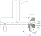
Referring to fig. 1, 7 and 8, the melt distribution mechanism comprises a main pipe 11 and a branch system 12, and is used for connecting multi-station blowing and filling and sealing equipment, hot-melt glue of an extruder 1 is required to be respectively transmitted into at least two annular glue cylinder extrusion heads 2 for processing glue cylinders, so that the blowing and filling and sealing of plastic ampoule bottles cannot be carried out synchronously due to different glue feeding amounts among the independent station blowing and sealing equipment. The main pipe 11 is connected with the glue outlet of the extruder 1, the branch system 12 at the tail end of the main pipe 11 is connected with each station blowing and filling and sealing equipment, and the glue outlet amount is regulated under the action of the branch system 12, so that the glue barrel processed by each station blowing and sealing equipment meets the production requirement.
Referring to fig. 1, 7 and 8, the branching system 12 includes two branching pipes 121, one end of each branching pipe 121 is connected to the main pipe 11, the other end is connected to the extrusion head 2, and glue in the main pipe 11 is transferred into the extrusion head 2 along the branching pipe 121 to form a glue cylinder. The branch pipes 121 are symmetrically distributed along the main pipe 11. The branched pipe 121 is provided with a regulating and controlling component 13, and when colloid is transmitted through the branched pipe 121, the colloid flow rate from the hole of the regulating and controlling component 13 on the branched pipe 121 to the branched pipe 121 is controlled, so that the colloid is transmitted to the colloid feeding amount of the extruding head 2. The regulating component 13 comprises a regulating column 131 and a thread groove 132, the thread groove 132 is arranged on the outer wall of the branch pipe 121, a through hole 133 is formed in the bottom of the thread groove 132 in a penetrating mode and extends to the inner wall of the branch pipe 121, the regulating column 131 is connected with the thread groove 132 in a threaded mode, and a regulating part at the end portion of the regulating column 131 extends into the branch pipe 121 along the through hole 133 to control glue outlet of the colloid in the branch pipe 121. The adjusting part comprises a cylindrical block 135 and a ball block 134, wherein the cylindrical block 135 is connected to the end of the adjusting column 131 and penetrates into the through hole 133 to move along the inner wall of the through hole 133 to be abutted in the branch pipe 121, and the section of the branch pipe 121 is controlled by the cylindrical block 135 so as to change the colloid flow transmission of the branch pipe 121. The ball block 134 is connected to the end of the cylindrical block 135, the ball block 134 is abutted to the branch pipe 121 to transmit the hole colloid flow, the radian of the end of the ball block 134 can reduce the adsorption of colloid, the colloid discharge amount can be adjusted in a large range, no dead angle exists, and no molten gel carbonization phenomenon exists. The thread groove 132 is arranged along the outer wall of the branch pipe 121 and is perpendicular to the axis of the branch pipe 121, so that the processing of the branch pipe 121 can be facilitated. And the cylindrical blocks 135 are distributed along the radial direction of the cross section circle of the branch pipe 121, so that the phenomenon that the glue is carbonized due to the glue adsorption residue caused by the inclination of the cylindrical blocks 135 is reduced.
Referring to fig. 7, 8 and 9, in order to reduce contact wear caused by the screw movement of the adjusting column 131 in the screw groove 132 when the adjusting column is abutted against the bottom of the screw groove 132, a buffer block 136 is sleeved on the outer wall of the cylindrical block 135, the buffer block 136 is abutted against the end of the adjusting column 131, the buffer block 136 and the cylindrical block 135 are driven to integrally move through the adjusting column 131 when the adjusting column 131 is moved in a screw manner, and the ball block 134 is driven to reach a final position by the screw movement of the adjusting column 131, the screw wear of the adjusting column 131 is reduced and the service life of the adjusting column 131 is prolonged.
Referring to fig. 1 and 10, the extrusion head 2 is further provided with a temperature control assembly 29, the temperature control assembly 29 comprises a temperature control joint 291, the temperature control joint 291 is arranged on the die holder 21, and the temperature in the extruder 1 is monitored and regulated through the temperature control joint 291, so that the temperature of the colloid in the die cavity 243 reaches the production requirement, and the temperature control joint 291 is uniformly distributed on the die holder 21.
Referring to fig. 1, 2 and 3, the fastening assembly 214 includes a fastening screw 2141, the fastening screw 2141 is disposed on the die holder 21, the fastening screw 2141 is threaded through the die holder 21 and is connected with the die core plate 241 by threading, and the die core plate 241 is fixed on the die holder 21 by the fastening screw 2141 and is installed between the upper platen 211 and the lower platen 212.
Referring to fig. 1, 2 and 3, in order to make the gel smoothly flow out along the die cavity 243 and compensate for the extrusion pressure loss of the gel, the pressure values from the feeding end of the die cavity 243 to the discharging end of the die cavity 243 are uniform, so that the extrusion pressures of the gel are uniform. The buffer 242 includes a first protrusion 2421 and a second protrusion 2422, and the first protrusion 2421 and the second protrusion 2422 are spaced apart to transfer the glue along the first protrusion 2421 to the second protrusion 2422, and the first protrusion 2421 and the second protrusion 2422 flow the glue along the mold cavity 243 to compensate for the pressure loss and reduce the gas generated in the mold cavity 243 by the glue, so that the glue barrel formed in the extrusion head 2 meets the production requirement.
Referring to fig. 1, 2 and 6, a discharge shunt tube is provided on the extrusion head 2. The blanking shunt tubes comprise a main flow tube 22 and a shunt assembly 23, when the plastic ampoule bottle is subjected to blow molding and filling, plastics are heated through the extruder 1, hot-melt colloid is conveyed through the extruder 1, the colloid is conveyed to the main flow tube 22, colloid conveyed through the shunt assembly 23 and retrograde shunt treatment are carried out on the colloid conveyed through the main flow tube 22, the colloid is conveyed to two sides of the extrusion head 2 for glue feeding, the colloid is evenly fed along the two sides of the extrusion head 2, and the uniformity of glue output in the extrusion head 2 is ensured, so that the thickness of a glue cylinder is consistent, and the plastic ampoule bottle is molded.
Referring to fig. 1, 11 and 12, an oxygen concentration detection mechanism is further arranged on the extrusion head 2, the oxygen concentration detection mechanism comprises an extruder 1, the outlet end of the extruder 1 is provided with the extrusion head 2, the extrusion head 2 is provided with a filling and sealing machine 3, the filling and sealing machine 3 is provided with a filling needle 31, the extrusion head 2 is provided with an oxygen concentration detection assembly, when liquid medicine is filled in an ampoule bottle, the oxygen concentration in the extrusion head 2 is detected through the oxygen concentration detection assembly, and when the oxygen concentration is less than 3%, the liquid medicine can be filled in the ampoule bottle.
Referring to fig. 1, 11 and 12, the oxygen concentration detection assembly 28 includes an online oxygen detector 281, a probe of the online oxygen detector 281 is arranged in the extrusion head 2 and along the adjacent filling needle 31, the oxygen concentration near the glue cylinder is monitored in real time by the online oxygen detector 281, and the oxygen concentration monitoring result is fed back to a controller, and the controller is connected with an alarm device and carries out feedback alarm when the oxygen concentration is more than 3%. The alarm device comprises an alarm bell, and the alarm bell reminds a filling worker that the liquid medicine is not suitable for filling due to the too high oxygen concentration.
Referring to fig. 1, 11 and 12, in order to avoid too high oxygen concentration at the filling needle 31 during filling of liquid medicine, a gas conveying device 282 is arranged on the extrusion head 2, inert gas nitrogen is conveyed into the extrusion head 2 through the gas conveying device 282, the filling needle 31 is isolated from oxygen, a rubber cylinder to be filled extruded from the extrusion head 2 through the gas conveying device 282 is isolated from oxygen, and the condition that the monitoring of ampoule bottles after liquid medicine filling is unqualified due to too high oxygen content in the rubber cylinder is avoided, so that the ampoule bottles cannot be used is avoided.
Referring to fig. 1, 11 and 12, the gas delivery device 282 includes a nitrogen cylinder 2821, a filter 2822 and a gas pipe 2823, the filter 2822 connects the nitrogen cylinder 2821 and the gas pipe 2823 to transmit nitrogen to the extrusion head 2 along the gas pipe 2823, a branch pipe 2824 is arranged at the tail end of the gas pipe 2823, the branch pipe 2824 is arranged along the gap of the filling needle 31 and is abutted to the rubber cylinder, the extrusion head 2 is filled with nitrogen, oxygen in the extrusion head 2 is discharged, the oxygen concentration is detected by an online oxygen detector 281, the rubber cylinder on the extrusion head 2 transmitted to the forming die 4 is filled by the filling needle 31, and the rubber cylinder is die cast into an ampoule.
Referring to fig. 1, 2 and 10, the extruder 1 is further provided with a temperature detection mechanism, the temperature detection mechanism comprises a temperature detection assembly 25 including a micro temperature sensor 251, the micro temperature sensor 251 is arranged on the outer wall of the filling needle 31 and extends into an ampoule along with the filling needle 31, the temperature detection on the inner wall of the ampoule is performed through the micro temperature sensor 251 on the outer wall of the filling needle 31, and temperature information is fed back to a wireless temperature acquisition instrument for observation. The position of the micro temperature sensor 251 is arranged at a position close to the mouth of the ampoule bottle.
Referring to fig. 1, 2 and 10, when the micro temperature sensor 251 is set to 1 group, the micro temperature sensor 251 is set at a position close to the mouth of the ampoule bottle, and when the micro temperature sensor 251 is set to at least 2 groups, the micro temperature sensor 251 is set on the filling needle 31 and is arranged along the outer wall of the filling needle 31 and is located in the ampoule bottle for detecting the temperature of the inner wall of the ampoule bottle. The miniature temperature sensor 251 is arranged on the filling needle 31 to detect the temperature of the inner wall of the ampoule bottle, and the filling requirement of the liquid medicine can be met when the temperature in the ampoule bottle is lower than 60 ℃, so that the liquid medicine of the ampoule bottle can be filled at the moment.
Referring to fig. 1, 2 and 3, a rubber cylinder thickness adjusting mechanism is further provided in the extrusion head 2, the rubber cylinder thickness adjusting mechanism includes a die holder 21, an upper platen 211, a lower platen 212 and a die core plate 241, the upper platen 211 and the lower platen 212 are connected and fixed on the die holder 21, a die cavity 243 is formed by arranging the die core plate 241 on the die holder 21 and between the upper platen 211 and the lower platen 212, and the wall thickness of the rubber cylinder is controlled by moving the rubber cylinder along the die cavity 243 to form the rubber cylinder.
Referring to fig. 1, 2 and 3, an adjusting component 26 is arranged on the lower pressure plate 212 and the mold core plate 241 and controls the flow of the glue at the discharge port of the mold cavity 243 through the adjusting component 26, so that the wall thickness of the glue cylinder is controlled, and the wall thickness of the formed glue cylinder is adjusted according to the wall thickness of the formed glue cylinder, so that the wall thickness of the formed glue cylinder meets the production requirement. The adjusting component 26 is connected with a driving component 27, and the driving component 27 operates to drive the adjusting component 26 to operate so as to control the wall thickness of the rubber cylinder.
Referring to fig. 1, 2 and 3, the adjusting assembly 26 includes a first adjusting portion 261 and a second adjusting portion 262, the first adjusting portion 261 adjusts the gap size of the discharge end of the die cavity 243 along the length direction of the die holder 21, and the second adjusting portion 262 adjusts the gap size of the die cavity 243 along the width direction of the die holder 21. The first adjusting part 261 includes a space plate 213, an adjusting plate 2611, a guide plate 2612 and a guide block 2613, the space plate 213 is arranged between the first upper pressing plate 211 and the lower pressing plate 212, a gap communicated with the cavity 243 is formed between the space plate 213 and the mold core plate 241, a containing groove communicated with the cavity 243 is formed in the space plate 213, the guide block is slidingly arranged along the containing groove, a chute is arranged along the length direction of the lower pressing plate 212, the adjusting plate 2611 moves along the chute and adjusts the gap between the adjusting plate 2611 and the mold core plate 241, the guide block 2613 is arranged at the lower end of the mold core plate 241, a gap is formed between the adjusting plate 2613 and the guide block 2611, and glue flows out of the forming glue cylinder along the gap between the adjusting plate 2611 and the guide block 2613, and the wall thickness of the glue cylinder is controlled by controlling the gap between the adjusting plate 2611 and the guide block 2613 through the first adjusting part 261. The second adjusting portion 262 includes an adjusting block 2621, the adjusting block 2621 is provided on the lower platen 212 and moves along the lower platen 212, the adjusting block 2621 is disposed along both sides of the width direction of the core plate 241, and the wall thickness of the packing element is controlled by controlling the distance between the adjusting block 2621 and the core plate 241. The adjustment plate 2611 moves together with the guide plate 2612 in a fixed connection, and the end of the guide plate 2612 facing the die plate 241 is continuously provided with the end face of the adjustment plate 2611.
Referring to fig. 1, 2 and 3, the driving assembly 27 includes a first driving portion 271 and a second driving portion 272, the first driving portion 271 is connected with the adjusting plate and the guiding plate 2612 for driving the adjusting plate and the guiding plate 2612 to move so as to adjust the wall thickness of the glue cylinder, the second driving portion 272 is disposed on the lower pressing plate 212, and the second driving portion 272 is connected with the adjusting block and is used for driving the adjusting block to move so as to control the wall thickness of the glue cylinder. The first driving part 271 includes a first driving screw 2711 and an adjusting screw 2712, the adjusting screw 2712 is threaded through the space plate 213 and the guide plate 2612, and the first driving screw 2711 is threaded through the lower pressure plate 212 and the adjusting plate 2611 is rotatably connected. The second driving part 272 includes a second driving screw 2721, and the second driving screw 2721 is rotatably connected to the adjusting block 2621 by being threaded through the lower pressure plate 212.
Referring to fig. 1 and 4, the forming mold 4 comprises a head mold 41 and a body mold 42, a balance type mold clamping mechanism is further arranged in the forming mold 4, the balance type mold clamping mechanism comprises a pushing component 43 and a balance component 44, when the rubber cylinder is conveyed into the forming mold 4, the pushing component 43 drives the body mold 42 to clamp the body of the ampoule bottle, and after filling the ampoule bottle with the filling liquid, the pushing component 43 drives the head mold 41 to clamp the head of the ampoule bottle, so that filling and sealing of the ampoule bottle are completed.
Referring to fig. 1 and 4, the pushing assembly 43 includes a first pushing portion 431 and a second pushing portion, the first pushing portion 431 drives the body mold 42 to be closed, and the second driving portion 272 closes the head mold 41. A balancing component 44 is arranged on the bottle body mould 42 and the head mould 41, and the head mould 41 and the bottle body mould 42 are driven to be stably clamped through the balancing component 44.
Referring to fig. 1 and 4, the balancing assembly 44 includes four tie rods 441, four tie rods 441 are provided, the tie rods 441 penetrate through the head mold 41 and the body mold 42, and four tie rods 441 penetrate through the head mold 41 and the body mold 42 to guide the head mold 41 and the body mold 42, so that the head mold 41 and the body mold 42 are stably clamped. The body mold 42 includes a fixed mold 45, a movable mold 46 and a body mold 423, a pull rod 441 is fixedly connected to the fixed mold, and the pull rod 441 penetrates through the movable mold 46, the body mold 423 is fixed to the movable mold 46, and the movable mold 46 is driven to move along the pull rod 441 by a first pushing portion 431, so that the body mold 42 is closed, and the head mold 41 is driven to close under the action of a second pushing portion to complete the molding and packaging of the ampoule.
Referring to fig. 1 and 4, the first pushing portion 431 includes a first mold closing cylinder 4311, the first mold closing cylinder 4311 is provided on the fixed platen 45, an output end of the first mold closing cylinder 4311 is connected to the movable platen 46, and the first mold closing cylinder 4311 pushes the movable platen 46 to close the body mold 423 to complete the body mold closing of the ampoule. The second pushing part comprises a second clamping cylinder 4321, and the head die 41 is driven to clamp by the second clamping cylinder 4321 to complete the bottle head clamping of the ampoule bottle. The head mold 41 comprises a head mold plate 411, the head mold plate 411 is arranged on the movable mold plate 46 and is connected to the movable mold plate 46 through a second mold closing oil cylinder 4321, and the output end of the second mold closing oil cylinder 4321 is connected with the head mold plate 411 and drives the head mold plate 411 to mold and finish the mold closing and molding of the bottle head of the ampoule bottle, so that the filling and sealing of the ampoule bottle are finished. And the first mold closing oil cylinders 4311 are symmetrically distributed along the fixed mold plate 45, and the second mold closing oil cylinders 4321 are symmetrically distributed along the movable mold plate 46, so that the uniform mold closing of the bottle body mold plate 423 and the head mold plate 411 is ensured, the uneven molding of ampoule bottles is avoided, and the condition that the production requirement is not met is avoided.
Referring to fig. 1 and 13, the bottom end of the forming mold 4 is further provided with a synchronous clamping mechanism 5, the synchronous clamping mechanism 5 comprises a clamping component 51, a spreading component 52 and a lifting component 53, when the ampoule bottle is formed, the formed ampoule bottle is clamped through the clamping component 51, when the ampoule bottle is continuously formed at the last station, the formed ampoule bottle is clamped through the clamping component 51, the formed ampoule bottle is continuously formed in the forming mold 4, the discharge end of the extrusion head 2 is naturally formed by falling, the clamping component 51 is driven to move downwards along with the falling speed of the rubber cylinder through the lifting component 53, and the formed ampoule bottle is prevented from deforming due to the fact that gravity is applied to the rubber cylinder by the formed ampoule bottle, so that the formed ampoule bottle does not meet the production requirement.
Referring to fig. 1 and 13, the clamping assembly 51 includes a clamping plate 511, and the clamping plate 511 clamps adjacent ampoule bottles molded in the molding die 4, so that ampoule bottles molded in the molding die 4 are prevented from pulling down a rubber tube naturally flowing in the extrusion head 2, and the wall thickness of the ampoule bottles is not satisfied with production requirements. The junction between adjacent ampoule is pressed from both sides tightly under the effect of grip block 511, and the ampoule of die sinking shaping in forming die 4 is unanimous along with the natural speed that drops of packing element under the centre gripping of grip block 511, thereby avoids the ampoule of grip block 511 centre gripping to drop down the wall thickness that the packing element leads to the packing element because of gravity reason to change, thereby does not satisfy the production demand. The both sides of grip block 511 are provided with baffle 512, avoid ampoule to collide and cause the damage when the centre gripping ampoule removes, protect the ampoule that falls.
Referring to fig. 1 and 13, the opening assembly 52 is connected to the clamping plate 511 for opening the clamping plate 511, the opening assembly 52 includes a lifting plate 521 and a bidirectional threaded rod 522, the lifting plate 521 is slidably disposed along the frame, the bidirectional threaded rod 522 is rotatably connected between the connecting plates, the connecting plates are fixed on the lifting plate 521, a driving source is disposed at an end of the bidirectional threaded rod 522, and the driving source drives the bidirectional threaded rod 522 to rotate to drive the clamping plate 511 to move along the bidirectional threaded rod 522 or deviate from each other. The driving source includes a stepping motor 523, the stepping motor 523 is disposed on the lifting plate 521, and an output shaft of the stepping motor 523 is fixed to an end of the bidirectional threaded rod 522. When the ampoule bottle bottom in the forming die 4 is clamped, a forward rotating signal is given to the stepping motor 523 to drive the stepping motor 523 to rotate so as to drive the clamping plate 511 to move oppositely on the bidirectional threaded rod 522 to clamp the ampoule bottle, when the forming of the ampoule bottle in the forming die 4 is completed, the clamping plate 511 is used for driving the ampoule bottle in the forming die 4 to move together and the dropping speed of the rubber tube in the extrusion head 2 is consistent, after the rubber tube is abutted in the forming die 4, the reverse rotating signal is given to the stepping motor 523 to drive the bidirectional threaded rod 522 to reversely rotate so as to drive the clamping plate 511 to deviate on the bidirectional threaded rod 522, and the clamping plate 511 is moved to the lower part of the forming die 4 to sequentially circularly work on the ampoule bottle to be formed and the reverse clamping.
Referring to fig. 1 and 13, the lifting assembly 53 includes a lifting frame 531 and a lifting cylinder 532, the lifting frame 531 is arranged on a frame, the lifting cylinder 532 is arranged on the lifting frame 531, the lifting cylinder 532 is arranged on the lifting plate 521, after the ampoule bottle is molded and encapsulated in the molding die 4, the clamping plate 511 is opened through the stepping motor 523, the lifting plate 521 is driven to move along the lifting frame 531 by the lifting cylinder 532, and the clamping plate 511 is moved to the lower side of the molding die 4 to clamp and support the ampoule bottle flat bottom to be molded. The lifting frame 531 is provided with a sliding groove, the lifting plate 521 moves along the sliding groove, and the lifting plate 521 is limited and guided through the sliding groove, so that the movement stability of the lifting plate 521 is ensured. The lifting plate 521 is arranged to be arc-shaped towards one end of the chute, so that the abutting friction force between the lifting plate 521 and the bottom of the chute is reduced, and the lifting plate 521 moves more stably. The lifting frame 531 is provided with a level sensor 533, and the levelness of the clamping plate 511 is detected by the level sensor 533, and when the clamping plate 511 is inclined, a signal is sent out and the feedback reminds a worker to adjust the angle of the clamping plate 511.
Referring to fig. 1, 14 and 15, as another modification of the present embodiment, the synchronous clamping mechanism 5 includes a clamping portion 54, an opening portion 55 and a lifting portion 56, and when clamping the ampoule in the molding die 4, the tail end of the ampoule is clamped by the clamping portion 54, the clamping and opening of the clamping portion 54 are performed by the opening portion 55, and the clamping portion 54 is driven to move up and down in a straight line by the lifting portion 56 to convey the molded ampoule out of the molding die 4. The clamping portion 54 includes a first clamping plate 541 and a second clamping plate 542, and the clamping and opening of the first clamping plate 541 and the second clamping plate 542 are controlled by the opening portion 55 by moving the first clamping plate 541 and the second clamping plate 542 relative to each other to clamp the tail end of the ampoule bottle. The stretching part 55 comprises a stretching cylinder 551, a first stretching rack 552, a second stretching rack 553, a synchronous gear 554 and a manufacturing frame, wherein the stretching cylinder 551 is arranged on the supporting frame 555, the first stretching rack 552 is connected with the stretching cylinder 551, the first stretching rack 552 is meshed with the second stretching rack 553 through the synchronous gear 554, the first stretching rack 552 is fixed with the first clamping plate 541, the second stretching rack 553 is fixed with the second clamping plate 542, and the stretching cylinder 551 operates to drive the first stretching rack 552 to slide to drive the synchronous gear 554 to drive the second stretching rack 553 to slide, so that the clamping and the opening and the closing of the first clamping plate 541 and the second clamping plate 542 are realized. The clamping part 54 is driven to move up and down linearly along the frame by the lifting part 56. The lifting part 56 comprises lifting rods 561, driving wheels 562, a conveyor belt 563, sliding plates 564, sliding rails 565 and a driving motor 566, wherein the lifting rods 561 are fixed on a frame, the driving wheels 562 are rotatably arranged on the lifting rods 561, the tensioned conveyor belts 563 are sleeved on the outer walls of the two driving wheels 562 on the same lifting rod 561, the sliding rails 565 are arranged on the lifting rods 561, the sliding plates 564 slide along the sliding rails 565, the driving motor 566 is connected to the rotating shaft ends of the driving wheels 562, the sliding plates 564 are connected with the supporting frames 555, the sliding plates 564 are fixedly connected with the conveyor belts 563, and the driving motor 566 is used for driving the driving wheels 562 to rotate to drive the conveyor belts 563 to rotate so as to move the sliding plates 564 along the sliding rails 565. Thereby drive support frame 555 reciprocates, when moving the discharge position with support frame 555, just strut the output shrink of cylinder 551 to drive first rack 552 and move first rack 552 through synchronizing gear 554 and drive first rack 552 and second rack 553 and prop up rack 552 and move in opposite directions and open first splint 541 and second splint 542 and carry out the ejection of compact of shaping ampoule.
Referring to fig. 1, 14 and 15, a filling needle 31 is provided on a filling machine, the filling needle 31 penetrates through an extrusion head 2 and extends into a rubber cylinder, when ampoule bottle forming is carried out, a servo push rod drives a forming die 4 to move upwards and clamp two sides of the rubber cylinder, a first clamping cylinder 4311 drives a body die 42 to clamp a row of ampoule bottles, liquid medicine is filled into the bodies of the ampoule bottles through the filling needle 31 on the filling machine, after the liquid medicine filling is finished, a head die 41 is driven to clamp the ampoule bottles through a second clamping cylinder 4321 on a moving template 46, a first clamping plate 541 and a second clamping plate 542 on a synchronous clamping mechanism 5 are driven to clamp tail ends of the ampoule bottles, a driving motor 566 is driven to move downwards and drive the forming die 4 to move downwards under the action of the servo push rod, at the moment, the first clamping cylinder 4311 opens the body die 42 and the second clamping cylinder 4321 to drive the head die to convey the formed bottles into the forming die 4, after the liquid medicine filling is finished, a transmission speed of the driving belt 563 is controlled to be consistent with the extrusion head 2 and the tail ends of the ampoule bottles are driven to move upwards and the clamping plate 542 to clamp the ampoule bottles at the two sides of the corresponding positions, and the two clamping plates are driven to move the corresponding to the extrusion head 542, and the ampoule bottles are clamped at the two sides of the corresponding clamping plates 542 are driven to be clamped by the corresponding to the extrusion head 2 when the extrusion head is carried out, and the ampoule bottles are clamped by the clamping plate 542 is kept at the position of the corresponding to the end of the extrusion head 2, and the two clamping plates is kept at the end is stretched to be clamped by the corresponding to the end of the extrusion die is positioned and clamped to the ampoule bottle is positioned to be stretched to the ampoule bottle is positioned and clamped.
The working principle of the multi-station blowing and filling and sealing equipment is as follows: when the liquid medicine filling of ampoule, heat the plastic original paper to the molten state through extruder 1, through the fuse-element dispensing mechanism of extruder 1 tip, pass the colloid of molten state to among a plurality of shaping filling systems, carry out the preliminary shaping of colloid through extrusion head 2, control the flow of colloid through the die cavity 243 in the extrusion head and extrude the shaping packing element at the discharge gate of extrusion head 2, according to the demand of production, the wall thickness of control packing element is passed through adjusting part 26, pass the packing element into forming die 4, promote the movable die plate 46 to remove the body of bottle mould 42 in opposite directions through first compound hydro-cylinder 4311, carry out the filling liquid filling to the ampoule through filling needle 31 on the filling machine 3 and accomplish the filling of ampoule, order about the head template 411 compound die of ampoule through the second compound hydro-cylinder, thereby accomplish the filling seal of ampoule, order about ampoule through synchronous fixture 5 after accomplishing the filling of ampoule, order about ampoule and extrude the packing needle 31 on the extrusion head 2 through the constant and extrusion head 2 and extrusion die plate thickness control packing element according to the demand of production, pass through extrusion head 2 and follow-up extrusion die plate 31 and move the injection molding die 4 along with the extrusion die 4, realize that the injection molding efficiency of filling machine moves the filling needle 31 is moved along with the extrusion die 4, thereby realize the shaping efficiency of continuous filling and shaping of filling machine is realized.
Example 2
The difference between this embodiment and embodiment 1 is that the temperature detecting unit 25 includes a conventional temperature sensor, the conventional temperature sensor is disposed on the body mold 42, the conventional temperature sensor is used for detecting the body temperature of the ampoule, the conventional temperature sensor is disposed on the body mold 42 and disposed at two sides of the ampoule, and the body mold 42 is provided with cooling blocks for cooling the molded ampoule.
Example 3
The difference between this embodiment and embodiment 1 is that the end of the air pipe 2823 is provided with a rotary spray head, the rotary spray head is arranged in the extrusion head 2, the nitrogen in the nitrogen tank is transmitted to the rotary spray head through the air pipe 2823 by the filter 2822, and the nitrogen is transmitted to each position in the extrusion head 2 by the rotary spray head, so that the oxygen concentration in the extrusion head 2 is ensured to be lower than 3%, the liquid medicine is filled in the rubber cylinder by the filling needle 31, and the oxygen concentration in the rubber cylinder meets the standard of liquid medicine filling.
Example 4
The difference between this embodiment and embodiment 1 is that the temperature control assembly includes a heating plate, which is disposed on the upper platen 211 and the lower platen 212 and along the mold cavity 243, and continuously heats the colloid under the action of the heating plate when the colloid flows along the mold cavity 243, so as to avoid the colloid contacting the upper platen 211 and the lower platen 212 to conduct heat, and prevent the colloid from being cooled and adsorbed on the inner wall of the mold cavity 243, thereby preventing the transportation of the colloid from being blocked.
Example 5
The difference between this embodiment and embodiment 1 is that the adjusting assembly 26 includes an adjusting hopper, the adjusting hopper is inserted into the discharge hole of the mold cavity 243, the colloid flows out along the inner wall of the adjusting hopper, and the forming glue cylinder meets the production requirement, and the size of the adjusting hopper is adjusted according to the production specification, so that the glue cylinders with different sizes can be obtained to produce ampoule bottles with different sizes.
Example 6
The difference between this embodiment and embodiment 1 is that a flow adjusting portion is disposed on the shunt tube 2321, in order to control the flow of the gel entering the extrusion head 2, the flow adjusting portion is disposed at the output end of the shunt tube 2321, the flow adjusting portion includes an adjusting screw 2712, the adjusting screw 2712 penetrates the outer wall of the shunt tube 2321 and abuts against the shunt tube 2321, and the flow of the gel is controlled by controlling the cross-sectional area of the shunt tube 2321.
Example 7
The difference between this embodiment and embodiment 1 is that the adjusting assembly 26 includes an adjusting hopper, the adjusting hopper is inserted into the discharge hole of the mold cavity 243, the colloid flows out along the inner wall of the adjusting hopper, and the forming glue cylinder meets the production requirement, and the size of the adjusting hopper is adjusted according to the production specification, so that the glue cylinders with different sizes can be obtained to produce ampoule bottles with different sizes.
Example 8
The difference between this embodiment and embodiment 1 is that the first driving portion 271 includes a screw, the screw thread penetrates through the lower platen 212 and is rotationally connected with the adjusting plate 2611, the end portion of the screw is provided with a turntable, a plurality of groups of pin holes are provided on the outer wall of the lower platen 212 by arranging pins on the turntable, the screw is driven to rotate by rotating the turntable to drive the adjusting plate 2611 and the guide plate 2612 to integrally move, and the screw is fixed by adjusting the gap between the adjusting plate 2611 and the mold core plate 241 and inserting the pins through the turntable and the pin holes to prevent the screw from turning.
Example 9
The present embodiment is different from embodiment 1 in that the first driving part 271 includes a screw rod penetrating through the fixed die plate 45 and rotationally connecting an end of the screw rod with an end of the moving die plate 46, and the screw rod is driven to rotate by a stepping motor 523 connected to an end of the screw rod, and the circumferential rotation of the moving die plate 46 is restricted under the limit of the draw bar 441 so that the moving die plate 46 is axially moved along the screw rod, thereby driving the body die plate 423 to be clamped.
Example 10
The difference between the present embodiment and embodiment 1 is that the first pushing portion 431 adopts a first mold clamping servo push rod, the second pushing portion adopts a second mold clamping servo push rod, and the body mold 42 and the head mold 41 are respectively driven to mold by the first mold clamping servo push rod and the second mold clamping servo push rod, so that the operation is relatively simple and the cost is relatively low.
Example 11
The difference between this embodiment and embodiment 1 is that the spreader assembly 52 includes a spreader cylinder, the spreader cylinder is a bidirectional cylinder, two output ends of the spreader cylinder are connected to the clamping plate 511, the clamping plate 511 is opened through the output ends of the spreader cylinder by the work of the spreader cylinder to realize the clamping replacement of the clamping plate 511, the cyclic work is performed, and when the ampoule in the forming mold is clamped, the clamping plate 511 is contracted and clamped by the contraction of the two output ends of the spreader cylinder, so that the bottom end of the ampoule to be formed in the forming mold 4 is clamped by the clamping plate 511.
Example 12
The difference between this embodiment and embodiment 1 is that the lifting assembly 53 includes a screw rod, the screw rod is disposed on the lifting frame 531, and is connected to the lifting plate 521 through the screw rod, so as to drive the screw rod to rotate under the action of external force, thereby driving the lifting plate 521 to move along the lifting frame 531, driving the clamping block to move along the lifting frame 531 and clamping the ampoule bottle with the molding, and sequentially performing the circulation work. The end of the screw rod is provided with a motor, and the screw rod is driven to rotate by the external power of the motor, so that the lifting plate 521 is driven to drive the clamping plate 511 to integrally displace.
Example 13
The difference between this embodiment and embodiment 1 is that the regulating and controlling unit 13 includes a flow valve, and the flow valve is provided at the end of the branch pipe 121, so that the branch pipe 121 is connected to each extrusion head 2 via the flow valve, and the delivery of the gel is controlled by adjusting the parameters of the flow valve. The branched pipe 121 is connected with the extrusion head 2 through the flow valve, so that quantitative transmission of colloid can be controlled, but after blowing and filling and sealing are finished, the flow valve has a complex structure, and residual colloid is difficult to clean.
Example 14
The present embodiment is different from embodiment 1 in that in order to reduce the screw friction damage of the adjustment column 131 and the bottom of the screw groove 132, the end of the adjustment column 131 is provided in an arc shape, and when the adjustment column 131 is moved spirally, the friction damage between the adjustment column 131 and the bottom of the screw groove 132 is reduced by reducing the contact area of the adjustment column 131 and the bottom of the screw groove 132.
The above description is only of the preferred embodiments of the present invention and is not intended to limit the present invention, but various modifications and variations can be made to the present invention by those skilled in the art. Any modification, equivalent replacement, improvement, etc. made within the spirit and principle of the present invention should be included in the protection scope of the present invention.
Claims (11)
1. A multistation blows embedment equipment, its characterized in that: comprising the following steps:
an extruder (1), the extruder (1) being for forming and outputting a colloid in a molten state;
the melt distribution mechanism is used for respectively connecting the extruder (1) with a plurality of groups of molding encapsulation systems and uniformly distributing molten colloid and comprises a main pipe (11) and a branch system (12), wherein the main pipe (11) is connected with a glue outlet of the extruder (1), and the branch system (12) at the tail end of the main pipe (11) is connected with each molding encapsulation system;
The branch system (12) comprises two branch pipes (121), and a regulating and controlling component (13) is arranged on the branch pipes (121);
the regulating and controlling assembly (13) comprises a regulating column (131) and a thread groove (132), wherein the thread groove (132) is formed in the outer wall of the branch pipe (121), a through hole (133) penetrates through the bottom of the thread groove (132) to extend to the inner wall of the branch pipe (121), the regulating column (131) is in threaded connection with the thread groove (132), and a regulating part at the end part of the regulating column (131) extends into the branch pipe (121) along the through hole (133) to control the glue outlet of the glue in the branch pipe (121);
the adjusting part comprises a cylindrical block (135) and a spherical block (134), the cylindrical block (135) is connected with the end part of the adjusting column (131) and penetrates into the through hole (133), the cylindrical block (135) moves along the inner wall of the through hole (133) and stretches into the branched pipe (121), the section of the branched pipe (121) is controlled through the cylindrical block (135) so as to change the colloid flow transmission of the branched pipe (121), the spherical block (134) is connected with the end part of the cylindrical block (135) and stretches into the spherical block (134) to control the colloid flow transmission in the branched pipe (121), and the outer diameter of the cylindrical block (135) is smaller than the inner diameter of the branched pipe (121), so that a gap is reserved for the colloid to pass through all the time while the colloid flow is adjusted;
A buffer block (136) is sleeved on the outer wall of the cylindrical block (135), and the buffer block (136) is abutted against the end part of the adjusting column (131);
the molding and filling and sealing system is at least provided with 2 groups, and is used for molding the rubber cylinder to prepare ampoule bottles, filling and sealing liquid medicine of the ampoule bottles, and carrying out linear continuous operation and outputting the ampoule bottles.
2. The multi-station blowing and potting apparatus of claim 1 wherein: the molding filling and sealing system comprises a filling and sealing machine (3), an extrusion head (2) and a molding die (4);
the filling and sealing machine (3) is used for filling liquid medicine into the formed ampoule bottles;
the extrusion head (2) is used for preliminarily forming the rubber cylinder for the rubber body and conveying the rubber cylinder;
the forming die (4) is used for reprocessing the rubber cylinder, forming ampoule bottles and sealing the ampoule bottles filled with the liquid medicine.
3. A multi-station blow molding apparatus as defined in claim 2, wherein: the molding encapsulation systems are all arranged on the same plane.
4. A multi-station blow molding apparatus according to claim 3, wherein: the molding encapsulation systems on the same extrusion head are distributed symmetrically left and right along the melt distribution mechanism.
5. A multi-station blow molding apparatus according to claim 3, wherein: the molding encapsulation systems on the same extrusion head are arranged in a left-right staggered way along the melt distribution mechanism.
6. A multi-station blow molding apparatus as defined in claim 2, wherein: the branch system (12) is connected with at least two extrusion heads (2), and the branch system (12) is used for adjusting the glue outlet amount of the main pipe (11) for transporting glue.
7. A multi-station blow molding apparatus according to claim 3, wherein: extrusion head (2) include die holder (21), feed seat (215), top board (211) and holding down plate (212), die holder (21) with feed seat (215) are connected, top board (211) set up in on die holder (21), holding down plate (212) set up in the below of top board (211), extrusion head still includes:
a mold core assembly (24), wherein the mold core assembly (24) is arranged on the mold base (21), the mold core assembly (24) is positioned between the upper pressing plate (211) and the lower pressing plate (212), and the mold core assembly (24) is used for molding rubber cylinders;
the fastening assembly (214), the fastening assembly (214) is arranged on the die holder (21), and the fastening assembly (214) is used for connecting the die core assembly (24) and the die holder (21).
8. The multi-station blowing and potting apparatus of claim 7, wherein: still be provided with packing element thickness adjustment mechanism in extruding head (2), packing element thickness adjustment mechanism includes:
the adjusting assembly (26) is arranged on the lower pressing plate (212) and the mold core plate (241), and the adjusting assembly (26) moves along the bottom of the lower pressing plate (212) and is used for adjusting the size of a discharge hole of the mold cavity (243);
and the driving assembly (27) is connected with the adjusting assembly (26) and used for driving the adjusting assembly (26) to move along the bottom of the lower pressing plate (212).
9. A multi-station blow molding apparatus as defined in claim 2, wherein: the forming die (4) comprises a head die (41) and a body die (42), the head die (41) is connected with the body die (42), a balance type die clamping mechanism is further arranged on the head die (41) and the body die (42) and used for stably driving the head die (41) and the body die (42) to clamp or open.
10. The multi-station blowing and potting apparatus of claim 9 wherein: the balanced clamping mechanism comprises:
A pushing assembly (43), wherein the pushing assembly (43) is used for pushing the head mold (41) and the bottle body mold (42) to be clamped;
and the balance assembly (44) is used for connecting the pushing assembly (43) so that the pushing assembly (43) can push the head die (41) and the bottle body die (42) to be clamped or opened in a straight way.
11. The multi-station blowing and potting apparatus of claim 9 wherein: the forming die (4) bottom is provided with synchronous fixture (5), synchronous fixture (5) are used for the stable shaping of ampoule, synchronous fixture (5) include:
the clamping assembly (51) is arranged below the bottle body die (42), and the clamping assembly (51) is used for clamping the ampoule bottle molded in the bottle body die (42);
-a spreader assembly (52), the spreader assembly (52) being connected to the clamping assembly (51) and being adapted to open the clamping assembly (51) for outputting a shaped cooled ampoule;
and the lifting assembly (53) is connected with the clamping assembly (51) and used for driving the clamping assembly (51) to lift and repeatedly clamp ampoule bottles formed by the bottle body die (42).
Priority Applications (2)
| Application Number | Priority Date | Filing Date | Title |
|---|---|---|---|
| CN202111132142.XA CN113683045B (en) | 2021-09-27 | 2021-09-27 | Multistation blows embedment equipment |
| PCT/CN2022/110433 WO2023045589A1 (en) | 2021-09-27 | 2022-08-05 | Multi-station blow-fill-seal device |
Applications Claiming Priority (1)
| Application Number | Priority Date | Filing Date | Title |
|---|---|---|---|
| CN202111132142.XA CN113683045B (en) | 2021-09-27 | 2021-09-27 | Multistation blows embedment equipment |
Publications (2)
| Publication Number | Publication Date |
|---|---|
| CN113683045A CN113683045A (en) | 2021-11-23 |
| CN113683045B true CN113683045B (en) | 2023-06-06 |
Family
ID=78587437
Family Applications (1)
| Application Number | Title | Priority Date | Filing Date |
|---|---|---|---|
| CN202111132142.XA Active CN113683045B (en) | 2021-09-27 | 2021-09-27 | Multistation blows embedment equipment |
Country Status (2)
| Country | Link |
|---|---|
| CN (1) | CN113683045B (en) |
| WO (1) | WO2023045589A1 (en) |
Families Citing this family (11)
| Publication number | Priority date | Publication date | Assignee | Title |
|---|---|---|---|---|
| WO2017187262A1 (en) | 2016-04-25 | 2017-11-02 | Marc Andrew Koska | Medical delivery system |
| EP3710086A4 (en) | 2017-11-17 | 2021-11-17 | Koska Family Limited | SYSTEMS AND PROCESSES FOR FLUID DISPENSERS |
| US12544511B2 (en) | 2018-06-20 | 2026-02-10 | Koska Family Limited | Systems and methods for pre-filled dual-chamber medical agent delivery |
| USD1052082S1 (en) | 2020-06-01 | 2024-11-19 | Koska Family Limited | Sealed fluid container |
| CN113683045B (en) * | 2021-09-27 | 2023-06-06 | 湖南千山制药机械股份有限公司 | Multistation blows embedment equipment |
| CN114835078B (en) * | 2022-06-02 | 2024-12-17 | 楚天科技股份有限公司 | Continuous production blowing, filling and sealing equipment and application method thereof |
| CN116353882B (en) * | 2023-06-01 | 2023-09-12 | 湖南沃克能源科技有限公司 | Ampoule continuous filling and sealing equipment |
| CN221022259U (en) * | 2023-09-25 | 2024-05-28 | 楚天科技股份有限公司 | Blowing, filling and sealing integrated machine |
| CN117021542A (en) * | 2023-09-28 | 2023-11-10 | 南通顺裕包装材料有限公司 | Injection molding production line for bottle caps of cosmetic packaging bottles |
| CN117382145B (en) * | 2023-12-13 | 2024-02-13 | 河北三庆机械制造有限公司 | Continuous material-flowing double-station blow molding machine |
| CN117891224B (en) * | 2024-03-15 | 2024-05-24 | 山东国泰民安玻璃科技有限公司 | Production control method, equipment and medium for oral liquid bottle |
Family Cites Families (12)
| Publication number | Priority date | Publication date | Assignee | Title |
|---|---|---|---|---|
| US6254369B1 (en) * | 1998-10-16 | 2001-07-03 | Daniel M. Kelly | Extrusion die for forming a skin on reusable construction material for concrete forms |
| ITMI20050067A1 (en) * | 2005-01-21 | 2006-07-22 | Uniloy Milacron S R L | DEVICE AND METHOD FOR DYNAMIC CHECK MADE ON EXTRUSION HEADS FOR CABLE BODY BLOWING |
| CN201530125U (en) * | 2009-09-24 | 2010-07-21 | 苏州金纬机械制造有限公司 | Coating die for pipe production line |
| DE102012108374A1 (en) * | 2012-09-07 | 2014-03-13 | Harald Feuerherm | Process for producing blow molded plastic hollow bodies and multiple extrusion head for carrying out the process |
| CN104723536B (en) * | 2013-12-19 | 2017-09-22 | 楚天科技股份有限公司 | Plastic bottle row blows potting fixture |
| CN203726808U (en) * | 2013-12-19 | 2014-07-23 | 楚天科技股份有限公司 | Blowing, filling and sealing equipment for plastic bottles |
| CN203831761U (en) * | 2014-04-15 | 2014-09-17 | 浙江双林塑料机械有限公司 | Double-layer extruding mould with multiple pipes |
| US20160075073A1 (en) * | 2014-09-11 | 2016-03-17 | T.W. Womer & Associates, Llc | Flow controlled strand die |
| CN104986360A (en) * | 2015-07-15 | 2015-10-21 | 山东新华医疗器械股份有限公司 | Three-in-one plastic ampoule production process and device |
| CN106697352A (en) * | 2016-12-27 | 2017-05-24 | 楚天智能机器人(长沙)有限公司 | Blowing, filling and sealing drug production method and blowing, filling and sealing integrated machine |
| CN113683045B (en) * | 2021-09-27 | 2023-06-06 | 湖南千山制药机械股份有限公司 | Multistation blows embedment equipment |
| CN114906790A (en) * | 2022-06-02 | 2022-08-16 | 楚天科技股份有限公司 | Multi-station continuous production blowing, filling and sealing equipment |
-
2021
- 2021-09-27 CN CN202111132142.XA patent/CN113683045B/en active Active
-
2022
- 2022-08-05 WO PCT/CN2022/110433 patent/WO2023045589A1/en not_active Ceased
Also Published As
| Publication number | Publication date |
|---|---|
| CN113683045A (en) | 2021-11-23 |
| WO2023045589A1 (en) | 2023-03-30 |
Similar Documents
| Publication | Publication Date | Title |
|---|---|---|
| CN113683045B (en) | Multistation blows embedment equipment | |
| CN113683044A (en) | Blowing, filling and sealing equipment | |
| JP7788444B2 (en) | Apparatus and method for manufacturing plastic containers | |
| JP7149373B2 (en) | Molding apparatus and method | |
| CN103025504B (en) | For producing the equipment of plastic containers | |
| US4412806A (en) | Parison ejector for an injection molding apparatus | |
| CN114603824A (en) | Linear injection blowing filling sealing integrated plastic bottle packaging equipment | |
| CN111483153B (en) | Continuous production process of plastic bottles | |
| US3355763A (en) | Rotary parison head blow molding machine | |
| WO2023165086A1 (en) | Linear injection, blowing, filling and sealing integrated plastic bottle packaging apparatus | |
| WO2023165084A1 (en) | Linear-type injection, blowing, filling, and sealing integrated plastic bottle packaging device | |
| CN114603825A (en) | Linear injection blowing filling sealing integrated plastic bottle packaging equipment | |
| CN210100517U (en) | Shoemaking device | |
| DE69804456T2 (en) | ONE-STEP PROCESS WITH HIGH PRODUCTIVITY AND DEVICE FOR PRODUCING CONTAINERS FROM PLASTIC | |
| CN101827698B (en) | Device for stretch blow molding and method for producing semi-finished products | |
| CN217293461U (en) | Multi-station blowing, filling and sealing equipment | |
| EP1868787B1 (en) | Apparatus for transferring doses | |
| CN217051617U (en) | Blowing, filling and sealing equipment | |
| CN101804679A (en) | Dose Delivery Devices and Doses | |
| CN120134588A (en) | Plastic product forming device and method | |
| CN216070603U (en) | Plastic ampoule bottle forming and filling system and blowing filling and sealing equipment | |
| US3951636A (en) | Molding apparatus | |
| CN216070602U (en) | Synchronous clamping mechanism and blowing, filling and sealing equipment | |
| MX2007012845A (en) | Apparatus for transferring doses and dose. | |
| US11524441B2 (en) | Production of containers with recycling by twin-screw extruder |
Legal Events
| Date | Code | Title | Description |
|---|---|---|---|
| PB01 | Publication | ||
| PB01 | Publication | ||
| SE01 | Entry into force of request for substantive examination | ||
| SE01 | Entry into force of request for substantive examination | ||
| GR01 | Patent grant | ||
| GR01 | Patent grant |