CN113682280B - Servo adjustable wire brake system, control method, storage medium and terminal - Google Patents
Servo adjustable wire brake system, control method, storage medium and terminal Download PDFInfo
- Publication number
- CN113682280B CN113682280B CN202111010686.9A CN202111010686A CN113682280B CN 113682280 B CN113682280 B CN 113682280B CN 202111010686 A CN202111010686 A CN 202111010686A CN 113682280 B CN113682280 B CN 113682280B
- Authority
- CN
- China
- Prior art keywords
- pedal
- simulator
- brake
- stroke
- master cylinder
- Prior art date
- Legal status (The legal status is an assumption and is not a legal conclusion. Google has not performed a legal analysis and makes no representation as to the accuracy of the status listed.)
- Active
Links
Images


Classifications
-
- B—PERFORMING OPERATIONS; TRANSPORTING
- B60—VEHICLES IN GENERAL
- B60T—VEHICLE BRAKE CONTROL SYSTEMS OR PARTS THEREOF; BRAKE CONTROL SYSTEMS OR PARTS THEREOF, IN GENERAL; ARRANGEMENT OF BRAKING ELEMENTS ON VEHICLES IN GENERAL; PORTABLE DEVICES FOR PREVENTING UNWANTED MOVEMENT OF VEHICLES; VEHICLE MODIFICATIONS TO FACILITATE COOLING OF BRAKES
- B60T8/00—Arrangements for adjusting wheel-braking force to meet varying vehicular or ground-surface conditions, e.g. limiting or varying distribution of braking force
- B60T8/17—Using electrical or electronic regulation means to control braking
- B60T8/171—Detecting parameters used in the regulation; Measuring values used in the regulation
-
- B—PERFORMING OPERATIONS; TRANSPORTING
- B60—VEHICLES IN GENERAL
- B60T—VEHICLE BRAKE CONTROL SYSTEMS OR PARTS THEREOF; BRAKE CONTROL SYSTEMS OR PARTS THEREOF, IN GENERAL; ARRANGEMENT OF BRAKING ELEMENTS ON VEHICLES IN GENERAL; PORTABLE DEVICES FOR PREVENTING UNWANTED MOVEMENT OF VEHICLES; VEHICLE MODIFICATIONS TO FACILITATE COOLING OF BRAKES
- B60T13/00—Transmitting braking action from initiating means to ultimate brake actuator with power assistance or drive; Brake systems incorporating such transmitting means, e.g. air-pressure brake systems
- B60T13/10—Transmitting braking action from initiating means to ultimate brake actuator with power assistance or drive; Brake systems incorporating such transmitting means, e.g. air-pressure brake systems with fluid assistance, drive, or release
- B60T13/66—Electrical control in fluid-pressure brake systems
- B60T13/68—Electrical control in fluid-pressure brake systems by electrically-controlled valves
-
- B—PERFORMING OPERATIONS; TRANSPORTING
- B60—VEHICLES IN GENERAL
- B60T—VEHICLE BRAKE CONTROL SYSTEMS OR PARTS THEREOF; BRAKE CONTROL SYSTEMS OR PARTS THEREOF, IN GENERAL; ARRANGEMENT OF BRAKING ELEMENTS ON VEHICLES IN GENERAL; PORTABLE DEVICES FOR PREVENTING UNWANTED MOVEMENT OF VEHICLES; VEHICLE MODIFICATIONS TO FACILITATE COOLING OF BRAKES
- B60T8/00—Arrangements for adjusting wheel-braking force to meet varying vehicular or ground-surface conditions, e.g. limiting or varying distribution of braking force
- B60T8/17—Using electrical or electronic regulation means to control braking
- B60T8/172—Determining control parameters used in the regulation, e.g. by calculations involving measured or detected parameters
-
- B—PERFORMING OPERATIONS; TRANSPORTING
- B60—VEHICLES IN GENERAL
- B60T—VEHICLE BRAKE CONTROL SYSTEMS OR PARTS THEREOF; BRAKE CONTROL SYSTEMS OR PARTS THEREOF, IN GENERAL; ARRANGEMENT OF BRAKING ELEMENTS ON VEHICLES IN GENERAL; PORTABLE DEVICES FOR PREVENTING UNWANTED MOVEMENT OF VEHICLES; VEHICLE MODIFICATIONS TO FACILITATE COOLING OF BRAKES
- B60T8/00—Arrangements for adjusting wheel-braking force to meet varying vehicular or ground-surface conditions, e.g. limiting or varying distribution of braking force
- B60T8/32—Arrangements for adjusting wheel-braking force to meet varying vehicular or ground-surface conditions, e.g. limiting or varying distribution of braking force responsive to a speed condition, e.g. acceleration or deceleration
- B60T8/34—Arrangements for adjusting wheel-braking force to meet varying vehicular or ground-surface conditions, e.g. limiting or varying distribution of braking force responsive to a speed condition, e.g. acceleration or deceleration having a fluid pressure regulator responsive to a speed condition
- B60T8/40—Arrangements for adjusting wheel-braking force to meet varying vehicular or ground-surface conditions, e.g. limiting or varying distribution of braking force responsive to a speed condition, e.g. acceleration or deceleration having a fluid pressure regulator responsive to a speed condition comprising an additional fluid circuit including fluid pressurising means for modifying the pressure of the braking fluid, e.g. including wheel driven pumps for detecting a speed condition, or pumps which are controlled by means independent of the braking system
- B60T8/4072—Systems in which a driver input signal is used as a control signal for the additional fluid circuit which is normally used for braking
- B60T8/4081—Systems with stroke simulating devices for driver input
-
- B—PERFORMING OPERATIONS; TRANSPORTING
- B60—VEHICLES IN GENERAL
- B60T—VEHICLE BRAKE CONTROL SYSTEMS OR PARTS THEREOF; BRAKE CONTROL SYSTEMS OR PARTS THEREOF, IN GENERAL; ARRANGEMENT OF BRAKING ELEMENTS ON VEHICLES IN GENERAL; PORTABLE DEVICES FOR PREVENTING UNWANTED MOVEMENT OF VEHICLES; VEHICLE MODIFICATIONS TO FACILITATE COOLING OF BRAKES
- B60T2270/00—Further aspects of brake control systems not otherwise provided for
- B60T2270/82—Brake-by-Wire, EHB
Landscapes
- Engineering & Computer Science (AREA)
- Transportation (AREA)
- Mechanical Engineering (AREA)
- Physics & Mathematics (AREA)
- Fluid Mechanics (AREA)
- Regulating Braking Force (AREA)
Abstract
Description
技术领域technical field
本发明涉及车辆线控制动技术领域,尤其涉及一种伺服可调式线控制动系统、控制方法、存储介质及终端。The invention relates to the technical field of vehicle brake-by-wire, in particular to a servo-adjustable brake-by-wire system, a control method, a storage medium and a terminal.
背景技术Background technique
请参阅图1,传统的线控制动系统中驾驶员通过踩踏制动踏板输入制动请求,线控制动系统根据踏板行程传感器(安装于线控制动主缸总成内)行程信号,将模拟器控制阀(常闭阀)上电,使得制动主缸回路1与踏板模拟器主缸相通,制动主缸油液随着踏板力输入顺利进入踏板模拟器,踏板模拟器主缸随着油液的进入,先后接触第一段弹簧和第二段弹簧,由两端弹簧模拟踏板感反馈给驾驶员。线控制动系统中主要包括踏板模拟器电磁阀、踏板模拟器主缸及弹簧等零部件,其中电磁阀主要负责控制踏板模拟器回路的通断、踏板感的模拟主要依靠踏板模拟器主缸及其弹簧进行反馈,受限于弹簧特性,踏板感反馈比较单一;且主要依靠模拟器主缸及弹簧反馈,而弹簧特性固化,踏板感不能调节,不能满足不同车型或者不同驾驶风格对踏板感调节的需求。Please refer to Figure 1. In the traditional brake-by-wire system, the driver inputs a braking request by stepping on the brake pedal. The control valve (normally closed valve) is powered on, so that the brake master cylinder circuit 1 communicates with the pedal simulator master cylinder, the brake master cylinder oil smoothly enters the pedal simulator with the pedal force input, and the pedal simulator master cylinder follows the oil. When the liquid enters, it contacts the first spring and the second spring successively, and the pedal feeling is simulated by the springs at both ends and is fed back to the driver. The brake-by-wire system mainly includes pedal simulator solenoid valve, pedal simulator master cylinder and spring and other components. The solenoid valve is mainly responsible for controlling the on-off of the pedal simulator circuit, and the pedal feeling simulation mainly relies on the pedal simulator master cylinder and the pedal simulator. The feedback of the spring is limited by the spring characteristics, and the pedal feel feedback is relatively simple; and mainly relies on the simulator master cylinder and spring feedback, but the spring characteristics are solidified, and the pedal feel cannot be adjusted, which cannot meet the adjustment of pedal feel for different models or different driving styles. demand.
发明内容SUMMARY OF THE INVENTION
本发明的目的在于提供一种伺服可调式线控制动系统及电动汽车,通过踏板模拟器电子控制单元任意设定踏板感,解决现有电动汽车踏板感的模拟主要依靠踏板模拟器主缸及其弹簧进行反馈,集成度较低,导致脚感模拟质量不高,无法主动调节模拟感的问题。The purpose of the present invention is to provide a servo-adjustable wire-controlled brake system and an electric vehicle, the pedal feel can be arbitrarily set by the pedal simulator electronic control unit, and the simulation of the pedal feel of the existing electric vehicle mainly relies on the pedal simulator master cylinder and its pedal simulator. The spring provides feedback and the integration is low, resulting in the low quality of foot feel simulation and the inability to actively adjust the simulation feel.
为了解决上述技术问题,本发明第一方面提出了伺服可调式线控制动系统,包括制动踏板和与所述制动踏板连接的制动主缸;还包括踏板模拟器电子控制单元、模拟器调压腔、模拟器主缸、伺服电机和传动件;In order to solve the above technical problems, the first aspect of the present invention proposes a servo-adjustable brake-by-wire system, which includes a brake pedal and a brake master cylinder connected to the brake pedal; and also includes a pedal simulator electronic control unit, a simulator Pressure regulating chamber, simulator master cylinder, servo motor and transmission parts;
所述模拟器调压腔与所述模拟器主缸相连,所述模拟器主缸与所述制动主缸相连;The simulator pressure regulating chamber is connected with the simulator master cylinder, and the simulator master cylinder is connected with the brake master cylinder;
所述踏板模拟器电子控制单元和所述伺服电机电连接,所述踏板模拟器电子控制单元被设置为接收所述制动主缸内发送的制动行程信号,根据所述制动行程信号和预设的踏板行程-踏板力特性表,实时调整所述伺服电机的旋转角度,进而调节所述模拟器调压腔的活塞行程,实现对所述模拟器主缸进液量的干预,完成对设定的踏板力特性模拟;The pedal simulator electronic control unit is electrically connected to the servo motor, and the pedal simulator electronic control unit is configured to receive a brake stroke signal sent in the brake master cylinder, and according to the brake stroke signal and The preset pedal stroke-pedal force characteristic table adjusts the rotation angle of the servo motor in real time, and then adjusts the piston stroke of the pressure regulating chamber of the simulator, so as to realize the intervention of the fluid intake of the main cylinder of the simulator, and complete the adjustment of the Set pedal force characteristic simulation;
所述传动件与所述伺服电机相连,所述传动件用于将所述伺服电机的输出轴的转动转换为所述模拟器调压腔的活塞的移动。The transmission part is connected with the servo motor, and the transmission part is used for converting the rotation of the output shaft of the servo motor into the movement of the piston of the pressure regulating chamber of the simulator.
在一些可能的实施方式中,所述制动主缸包括踏板行程传感器,所述踏板行程传感器与所述踏板模拟器电子控制单元电连接;所述踏板行程传感器被设置为感测所述制动踏板的位置变化以形成制动行程信号。In some possible implementations, the master brake cylinder includes a pedal travel sensor that is electrically connected to the pedal simulator electronic control unit; the pedal travel sensor is configured to sense the braking The position of the pedal changes to form the brake stroke signal.
在一些可能的实施方式中,所述踏板模拟器电子控制单元还被设置为预先设定踏板行程-踏板力特性表,所述踏板行程-踏板力特性表用于设定踏板行程和踏板力的转换比例。In some possible implementations, the pedal simulator electronic control unit is further configured to preset a pedal stroke-pedal force characteristic table, and the pedal stroke-pedal force characteristic table is used to set the difference between the pedal stroke and the pedal force. Conversion ratio.
在一些可能的实施方式中,还包括模拟器控制阀,所述模拟器控制阀设置在所述模拟器主缸与所述制动主缸之间;所述模拟器控制阀和所述踏板模拟器电子控制单元电连接;所述模拟器控制阀用于控制所述模拟器主缸和所述制动主缸之间的连通或断开。In some possible implementations, a simulator control valve is further included, the simulator control valve is arranged between the simulator master cylinder and the brake master cylinder; the simulator control valve and the pedal simulate The simulator electronic control unit is electrically connected; the simulator control valve is used to control the connection or disconnection between the simulator master cylinder and the brake master cylinder.
本发明第二方面提出了一种伺服可调式线控制动系统的控制方法,应用于上述的伺服可调式线控制动系统,包括:A second aspect of the present invention proposes a control method for a servo-adjustable wire-by-wire system, which is applied to the above-mentioned servo-adjustable wire-by-wire system, including:
获取制动主缸中行程传感器采集的制动行程信号;Obtain the brake stroke signal collected by the stroke sensor in the brake master cylinder;
根据所述制动行程信号和预设的踏板行程-踏板力特性表,实时调整伺服电机的旋转角度,以调节模拟器调压腔的活塞行程,实现对模拟器主缸进液量的干预;According to the brake stroke signal and the preset pedal stroke-pedal force characteristic table, adjust the rotation angle of the servo motor in real time to adjust the piston stroke of the pressure regulating chamber of the simulator, and realize the intervention on the fluid intake of the simulator master cylinder;
根据伺服电机的旋转角度,确定目标踏板力。Based on the rotation angle of the servo motor, the target pedal force is determined.
在一些可能的实施方式中,所述方法还包括,预先设定所述踏板行程-踏板力特性表,所述踏板行程-踏板力特性表用于设定踏板行程和踏板力的转换比例。In some possible implementations, the method further includes: presetting the pedal stroke-pedal force characteristic table, where the pedal stroke-pedal force characteristic table is used to set the conversion ratio of pedal stroke and pedal force.
在一些可能的实施方式中,所述方法还包括,根据所述制动行程信号,将模拟器控制阀进行通电,以使得制动主缸和模拟器主缸连通。In some possible implementations, the method further includes, according to the brake stroke signal, energizing a simulator control valve to communicate the master brake cylinder and the simulator master cylinder.
在一些可能的实施方式中,所述方法还包括,若检测到电气故障,则控制模拟器控制阀断电,并将所述制动主缸的油液输入到制动轮缸,以产生制动力。In some possible implementations, the method further includes, if an electrical fault is detected, controlling the simulator control valve to de-energize and input the oil of the master brake cylinder to the brake wheel cylinder to generate a brake power.
本发明还提供一种存储介质,其上存储有计算机程序,所述计算机程序被处理器执行时实现如上述的伺服可调式线控制动系统的控制方法。The present invention also provides a storage medium on which a computer program is stored, and when the computer program is executed by a processor, the above-mentioned control method of the servo-adjustable brake-by-wire system is implemented.
本发明还提供一种终端,包括一个或多个处理器和存储器。存储器与所述处理器耦接,用于存储一个或多个程序;当所述一个或多个程序被所述一个或多个处理器执行,使得所述一个或多个处理器实现如上述的伺服可调式线控制动系统的控制方法。The present invention also provides a terminal including one or more processors and a memory. A memory is coupled to the processor for storing one or more programs; when the one or more programs are executed by the one or more processors, the one or more processors implement the above-mentioned A control method for a servo-adjustable brake-by-wire system.
实施本发明,具有如下有益效果:Implement the present invention, have the following beneficial effects:
本方法通过电子控制单元任意设置踏板感,根据制动踏板输入的制动行程信号和踏板行程-踏板力特性表,实时调整伺服电机旋转角度,进而调节模拟器调压腔的活塞行程,实现对模拟器主缸进液量的干预,完成对设定的踏板力特性模拟,解决了现有踏板感模拟主要依靠模拟器主缸及弹簧反馈,而弹簧特性固化,导致踏板感不能调节的问题,使得踏板感可依据车型或驾驶者需求进行调整。In this method, the pedal feel is arbitrarily set by the electronic control unit, and the rotation angle of the servo motor is adjusted in real time according to the brake stroke signal input by the brake pedal and the pedal stroke-pedal force characteristic table, and then the piston stroke of the pressure regulating chamber of the simulator is adjusted to realize the correct adjustment The intervention of the fluid intake of the simulator master cylinder completes the simulation of the set pedal force characteristics, which solves the problem that the existing pedal feel simulation mainly relies on the simulator master cylinder and spring feedback, and the spring characteristics are solidified, resulting in the inability to adjust the pedal feel. The pedal feel can be adjusted according to the model or driver's needs.
附图说明Description of drawings
为了更清楚地说明本发明的技术方案,下面将对实施例或现有技术描述中所需要使用的附图作简单地介绍,显而易见地,下面描述中的附图仅仅是本发明的一些实施例,对于本领域普通技术人员来讲,在不付出创造性劳动的前提下,还可以根据这些附图获得其它附图。In order to illustrate the technical solutions of the present invention more clearly, the following briefly introduces the accompanying drawings required in the description of the embodiments or the prior art. Obviously, the accompanying drawings in the following description are only some embodiments of the present invention. , for those of ordinary skill in the art, other drawings can also be obtained based on these drawings without any creative effort.
图1是现有技术中的线控制动系统的结构示意图;1 is a schematic structural diagram of a brake-by-wire system in the prior art;
图2本发明伺服可调式线控制动系统的结构示意图;2 is a schematic structural diagram of a servo-adjustable wire-by-wire system of the present invention;
图3是本发明的踏板行程-踏板力特性表的关系示意图;3 is a schematic diagram of the relationship between the pedal stroke-pedal force characteristic table of the present invention;
图4是本发明的伺服可调式线控制动系统的控制方法的流程示意图;4 is a schematic flowchart of the control method of the servo-adjustable brake-by-wire system of the present invention;
图5是为本发明实施例提供的计算机终端设备的结构示意图。FIG. 5 is a schematic structural diagram of a computer terminal device according to an embodiment of the present invention.
其中,图中附图标记对应为:1、制动踏板;2、制动主缸;3、踏板模拟器电子控制单元;4、模拟器调压腔;5、模拟器主缸;6、伺服电机;7、传动件;8、踏板行程传感器;9、模拟器控制阀。Among them, the reference numerals in the figure correspond to: 1, brake pedal; 2, brake master cylinder; 3, pedal simulator electronic control unit; 4, simulator pressure regulating chamber; 5, simulator master cylinder; 6, servo Motor; 7. Transmission parts; 8. Pedal stroke sensor; 9. Simulator control valve.
具体实施方式Detailed ways
下面将结合本发明实施例中的附图,对发明实施例中的技术方案进行清楚、完整地描述,显然,所描述的实施例仅仅是本发明一部分实施例,而不是全部的实施例。基于本发明的实施例,本领域普通技术人员在没有做出创造性劳动的前提下所获得的所有其他实施例,都属于本发明保护的范围。The technical solutions in the embodiments of the present invention will be clearly and completely described below with reference to the accompanying drawings in the embodiments of the present invention. Obviously, the described embodiments are only a part of the embodiments of the present invention, not all of the embodiments. Based on the embodiments of the present invention, all other embodiments obtained by those of ordinary skill in the art without creative work fall within the protection scope of the present invention.
如图2所示,本发明公开了一种伺服可调式线控制动系统,伺服可调式线控制动系统,包括制动踏板1和与所述制动踏板1连接的制动主缸2;还包括踏板模拟器电子控制单元3、模拟器调压腔4、模拟器主缸5、伺服电机6和传动件7;As shown in FIG. 2 , the present invention discloses a servo-adjustable wire-by-wire system. The servo-adjustable wire-by-wire system includes a brake pedal 1 and a
模拟器调压腔4与模拟器主缸5相连,模拟器主缸5与制动主缸2相连;The simulator pressure regulating chamber 4 is connected with the
踏板模拟器电子控制单元3和伺服电机6电连接,踏板模拟器电子控制单元3被设置为接收制动主缸2内发送的制动行程信号,根据所述制动行程信号和预设的踏板行程-踏板力特性表,实时调整伺服电机6的旋转角度,进而调节模拟器调压腔4的活塞行程,实现对模拟器主缸5进液量的干预,完成对设定的踏板力特性模拟;The pedal simulator
传动件7与伺服电机6相连,传动件7用于将伺服电机6的输出轴的转动转换为模拟器调压腔4的活塞的移动。The
具体地,制动踏板1的一端与制动主缸2内的踏板传动组件连接,制动踏板1的另一端用于踩踏,踩踏传动组件的输出端与制动主缸2的活塞铰接,踩踏制动踏板1,制动踏板1将会通过传动组件带动制动主缸2的活塞在缸体内运动,进而使制动主缸2内的制动油液流出至其它相连的阀及结构件等。至于上述踏板传动组件可以为踏板杆,也可以为其他能够实现制动踏板1与制动主缸2的活塞之间动力传递的结构,在此不做详细赘述。制动主缸2的输出端通过模拟器控制阀9与模拟器主缸5连接,模拟器主缸5包括单段弹簧,模拟器主缸5连接模拟器调压腔连接,伺服电机6与传动件7连接,传动件7的输出轴与模拟器调压腔的活塞传动连接,伺服电机6为能够产生转动的电机,利用传动件7将伺服电机6的输出轴的转动转换为模拟器调压腔的活塞的移动,上述传动件7为齿轮齿条结构、丝母丝杠结构或涡轮蜗杆结构等,在此不做详细赘述。Specifically, one end of the brake pedal 1 is connected to the pedal transmission assembly in the
驾驶员通过踩踏制动踏板1输入制动请求,踏板模拟器电子控制单元3根据制动主缸2内的踏板行程传感器8(安装于线控制动主缸2总成内)获取制动行程信号,根据制动行程信号,踏板模拟器电子控制单元3将模拟器控制阀9上电,使得制动主缸2回路与模拟器主缸5、模拟器调压腔相通,其中模拟器控制阀9为常闭阀;同时踏板模拟器电子控制单元3根据行程传感器信号和预设的踏板行程-踏板力特性表,实时调整伺服电机6的旋转角度,根据伺服电机6的旋转角度进而调节模拟器调压腔的活塞行程,实现对模拟器主缸5进液量的干预,完成对设定的踏板力特性模拟。The driver inputs the brake request by stepping on the brake pedal 1, and the pedal simulator
踏板模拟器电子控制单元3可以是集中式或分布式的控制器,比如,可以是一个单独的单片机,也可以是分布的多块单片机构成,单片机中可以运行控制程序并进行信号传输,进而控制各部件实现其功能。The pedal simulator
稳态踏板力F与制动主缸2的踏板行程S存在以关系:The steady-state pedal force F has a relationship with the pedal stroke S of the master cylinder 2:
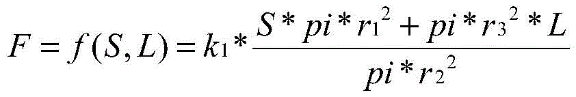
其中:pi为圆周率常数、r1为制动主缸2的活塞半径、r2为模拟器主缸5的活塞半径、r3为模拟器调压腔的活塞半径、k1为弹簧刚度系数、L为调压腔的活塞行程。Wherein: pi is the constant of pi, r 1 is the piston radius of the
由上式可知,F为变量(S,L)的函数表达,因此,可根据设定的踏板风格的S-F特性设定所需的调压腔活塞行程L与踏板行程S的对应关系,达到踏板感实时调节的目的。It can be seen from the above formula that F is the function expression of the variables (S, L). Therefore, the corresponding relationship between the required pressure regulating chamber piston stroke L and the pedal stroke S can be set according to the S-F characteristics of the set pedal style, so as to achieve the pedal stroke. sense the purpose of real-time adjustment.
通过选择在踏板模拟器电子控制单元3中预设的不同踏板力驾驶风格(踏板行程S-踏板力F曲线)即可输出所选风格的S-F特性,完成不同的踏板力模拟脚感,满足多种车型、多种驾驶风格的踏板模拟需求。By selecting different pedal force driving styles (pedal stroke S-pedal force F curve) preset in the pedal simulator
在一个实施例中,制动主缸2包括踏板行程传感器8,踏板行程传感器8与踏板模拟器电子控制单元3电连接;踏板行程传感器8被设置为感测制动踏板1的位置变化以形成制动行程信号。In one embodiment, the
在制动主缸2内有踏板行程传感器8,在驾驶员踩踏或松开制动踏板1时,踏板行程传感器8会形成制动行程信号,以体现驾驶员是否有制动或解除制动的操作,踏板模拟器电子控制单元3能够接收踏板行程传感器8的制动行程信号。通过踏板行程传感器8感测制动踏板1的位置变化已形成制动行程信号。There is a
在一个实施例中,踏板模拟器电子控制单元3还被设置为预先设定踏板行程-踏板力特性表,所述踏板行程-踏板力特性表用于设定踏板行程和踏板力的转换比例。In one embodiment, the pedal simulator
用户需根据实际的需求,预先通过踏板模拟器电子控制单元3设定踏板行程-踏板力特性表,踏板力行程-踏板力特性表中踏板行程与踏板力的输出关系如图3所示,通过根据自己的驾驶风格对踏板行程-踏板力特性表进行调整,满足不同车型和不同驾驶风格对踏板感调节的需求。The user needs to set the pedal stroke-pedal force characteristic table in advance through the pedal simulator
在一个实施例中,还包括模拟器控制阀9,模拟器控制阀9设置在模拟器主缸5与制动主缸2之间;模拟器控制阀9和踏板模拟器电子控制单元3电连接;模拟器控制阀9用于控制模拟器主缸5和制动主缸2之间的连通或断开。In one embodiment, a
模拟器控制阀9为常闭阀,当在驾驶员踩踏或松开制动踏板1时,踏板行程传感器8会形成制动行程信号,踏板模拟器电子控制单元3根据接收的踏板行程传感器8的制动行程信号,控制模拟器控制阀9上电,模拟器控制阀9打开,制动主缸2于模拟器主缸5之间连通。The
请参阅图4,本发明第二方面提出了一种伺服可调式线控制动系统的控制方法,应用于上述的伺服可调式线控制动系统,包括:Referring to FIG. 4 , a second aspect of the present invention provides a control method for a servo-adjustable brake-by-wire system, which is applied to the above-mentioned servo-adjustable brake-by-wire system, including:
S101、获取制动主缸2中行程传感器采集的制动行程信号;S101. Acquire a brake stroke signal collected by a stroke sensor in the
驾驶员踩下制动踏板1,在制动踏板1达到预设位置时,踏板模拟器电子控制单元3获取制动主缸2中行程传感器的制动行程信号;The driver steps on the brake pedal 1, and when the brake pedal 1 reaches the preset position, the pedal simulator
S102、根据所述制动行程信号和预设的踏板行程-踏板力特性表,实时调整伺服电机6的旋转角度,以调节模拟器调压腔的活塞行程,实现对模拟器主缸5进液量的干预;S102. According to the brake stroke signal and the preset pedal stroke-pedal force characteristic table, adjust the rotation angle of the servo motor 6 in real time to adjust the piston stroke of the pressure regulating chamber of the simulator, so as to realize the injection of liquid into the
根据制动行程信号和预设的踏板行程-踏板力特性表,实时调整伺服电机6的旋转角度;According to the brake stroke signal and the preset pedal stroke-pedal force characteristic table, adjust the rotation angle of the servo motor 6 in real time;
S103、根据伺服电机6的旋转角度,确定目标踏板力。S103 , determining the target pedal force according to the rotation angle of the servo motor 6 .
通过伺服电机6的旋转角度进而调节模拟器调压腔的活塞行程,实现对模拟器主缸5进液量的干预,完成对设定的踏板力特性模拟。Through the rotation angle of the servo motor 6, the piston stroke of the pressure regulating chamber of the simulator is adjusted, so as to realize the intervention of the liquid input amount of the
在一个实施例中,所述方法还包括,预先设定所述踏板行程-踏板力特性表,所述踏板行程-踏板力特性表用于设定踏板行程和踏板力的转换比例。In one embodiment, the method further includes: presetting the pedal stroke-pedal force characteristic table, where the pedal stroke-pedal force characteristic table is used to set the conversion ratio of pedal stroke and pedal force.
用户需根据实际的需求,预先设定踏板行程-踏板力特性表,通过根据自己的驾驶风格对踏板行程-踏板力特性表进行调整,满足不同车型和不同驾驶风格对踏板感调节的需求。Users need to pre-set the pedal stroke-pedal force characteristic table according to actual needs, and adjust the pedal stroke-pedal force characteristic table according to their own driving style to meet the needs of different models and different driving styles for pedal feel adjustment.
在一个实施例中,所述方法还包括,根据所述制动行程信号,将模拟器控制阀9进行通电,以使得制动主缸2和模拟器主缸5连通。In one embodiment, the method further includes, according to the brake stroke signal, energizing the
在一个实施例中,所述方法还包括,若检测到电气故障,则控制模拟器控制阀9断电,并将所述制动主缸2的油液输入到制动轮缸,以产生制动力。In one embodiment, the method further includes, if an electrical fault is detected, controlling the
具体地,模拟器控制阀9的状态为常闭状态,制动主缸2和模拟器主缸5为断开状态,当用户踩下制动踏板1,踏板模拟器电子控制单元3接收到制动行程信号,控制模拟器控制阀9上电,模拟控制阀打开,使得制动主缸2和模拟器主缸5之间连通;当线控制动系统遇到严重的电气故障时,将进入纯机械备份状态,此时,模拟器控制阀9断电并切断制动主缸2回路与模拟器主缸5的回路,使得制动主缸2油液可通过线控制动系统其他回路直接进入制动轮缸而产生一定的制动力,保证车辆制动力安全冗余。Specifically, the state of the
请参阅图5,本发明实施例提供一种终端,包括一个或多个处理器和存储器。存储器与所述处理器耦接,用于存储一个或多个程序,当所述一个或多个程序被所述一个或多个处理器执行,使得所述一个或多个处理器实现如上述任意一个实施例中的伺服可调式线控制动系统的控制方法。Referring to FIG. 5, an embodiment of the present invention provides a terminal including one or more processors and a memory. A memory is coupled to the processor for storing one or more programs that, when executed by the one or more processors, cause the one or more processors to implement any of the above A control method of a servo-adjustable brake-by-wire system in one embodiment.
处理器用于控制该计算机终端设备的整体操作,以完成上述的伺服可调式线控制动系统的控制方法的全部或部分步骤。存储器用于存储各种类型的数据以支持在该计算机终端设备的操作,这些数据例如可以包括用于在该计算机终端设备上操作的任何应用程序或方法的指令,以及应用程序相关的数据。该存储器可以由任何类型的易失性或非易失性存储设备或者它们的组合实现,例如静态随机存取存储器(Static Random AccessMemory,简称SRAM),电可擦除可编程只读存储器(Electrically Erasable ProgrammableRead-Only Memory,简称EEPROM),可擦除可编程只读存储器(Erasable ProgrammableRead-Only Memory,简称EPROM),可编程只读存储器(Programmable Read-Only Memory,简称PROM),只读存储器(Read-Only Memory,简称ROM),磁存储器,快闪存储器,磁盘或光盘。The processor is used to control the overall operation of the computer terminal device, so as to complete all or part of the steps of the above-mentioned control method of the servo-adjustable brake-by-wire system. The memory is used to store various types of data to support operation at the computer terminal device, such data may include, for example, instructions for any application or method for operation on the computer terminal device, as well as application-related data. The memory can be implemented by any type of volatile or nonvolatile storage device or a combination thereof, such as Static Random Access Memory (SRAM), Electrically Erasable Programmable Read-Only Memory (Electrically Erasable) Programmable Read-Only Memory (EEPROM for short), Erasable Programmable Read-Only Memory (EPROM), Programmable Read-Only Memory (PROM), Read-Only Memory (Read- Only Memory, referred to as ROM), magnetic memory, flash memory, magnetic disk or optical disk.
在一示例性实施例中,计算机终端设备可以被一个或多个应用专用集成电路(Application Specific 1ntegrated Circuit,简称AS1C)、数字信号处理器(DigitalSignal Processor,简称DSP)、数字信号处理设备(Digital Signal Processing Device,简称DSPD)、可编程逻辑器件(Programmable Logic Device,简称PLD)、现场可编程门阵列(Field Programmable Gate Array,简称FPGA)、控制器、微控制器、微处理器或其他电子元件实现,用于执行上述的伺服可调式线控制动系统的控制方法,并达到如上述方法一致的技术效果。In an exemplary embodiment, the computer terminal device may be implemented by one or more Application Specific Integrated Circuit (AS1C), Digital Signal Processor (DSP), Digital Signal Processing Device (Digital Signal Processing). Processing Device, referred to as DSPD), Programmable Logic Device (Programmable Logic Device, referred to as PLD), Field Programmable Gate Array (Field Programmable Gate Array, referred to as FPGA), controller, microcontroller, microprocessor or other electronic components , which is used to implement the above-mentioned control method of the servo-adjustable wire-by-wire system, and achieve the same technical effect as the above-mentioned method.
在另一示例性实施例中,还提供了一种包括程序指令的存储介质,该程序指令被处理器执行时实现上述任意一个实施例中的伺服可调式线控制动系统的控制方法的步骤。例如,该存储介质可以为上述包括程序指令的存储器,上述程序指令可由终端的处理器执行以完成上述的伺服可调式线控制动系统的控制方法,并达到如上述方法一致的技术效果。In another exemplary embodiment, there is also provided a storage medium including program instructions, the program instructions implementing the steps of the control method of the servo-adjustable brake-by-wire system in any one of the above-mentioned embodiments when the program instructions are executed by the processor. For example, the storage medium can be the above-mentioned memory including program instructions, and the above-mentioned program instructions can be executed by the processor of the terminal to complete the above-mentioned control method of the servo-adjustable brake-by-wire system, and achieve the same technical effect as the above method.
以上所揭露的仅为本发明的几个较佳实施例而已,当然不能以此来限定本发明之权利范围,因此依本发明权利要求所作的等同变化,仍属本发明所涵盖的范围。The above disclosures are only a few preferred embodiments of the present invention, which of course cannot limit the scope of the rights of the present invention. Therefore, equivalent changes made according to the claims of the present invention are still within the scope of the present invention.
Claims (10)
Priority Applications (1)
| Application Number | Priority Date | Filing Date | Title |
|---|---|---|---|
| CN202111010686.9A CN113682280B (en) | 2021-08-31 | 2021-08-31 | Servo adjustable wire brake system, control method, storage medium and terminal |
Applications Claiming Priority (1)
| Application Number | Priority Date | Filing Date | Title |
|---|---|---|---|
| CN202111010686.9A CN113682280B (en) | 2021-08-31 | 2021-08-31 | Servo adjustable wire brake system, control method, storage medium and terminal |
Publications (2)
| Publication Number | Publication Date |
|---|---|
| CN113682280A CN113682280A (en) | 2021-11-23 |
| CN113682280B true CN113682280B (en) | 2022-07-05 |
Family
ID=78584383
Family Applications (1)
| Application Number | Title | Priority Date | Filing Date |
|---|---|---|---|
| CN202111010686.9A Active CN113682280B (en) | 2021-08-31 | 2021-08-31 | Servo adjustable wire brake system, control method, storage medium and terminal |
Country Status (1)
| Country | Link |
|---|---|
| CN (1) | CN113682280B (en) |
Families Citing this family (2)
| Publication number | Priority date | Publication date | Assignee | Title |
|---|---|---|---|---|
| CN119968299A (en) * | 2022-12-30 | 2025-05-09 | 深圳引望智能技术有限公司 | Simulator, braking system, vehicle, pedal resistance control method and device |
| CN116620239A (en) * | 2023-05-30 | 2023-08-22 | 浙江吉利控股集团有限公司 | A multi-pedal feel control processing method, device, system, vehicle and medium |
Citations (3)
| Publication number | Priority date | Publication date | Assignee | Title |
|---|---|---|---|---|
| CN1623827A (en) * | 2003-12-05 | 2005-06-08 | 日信工业株式会社 | Braking device for vehicles |
| CN102481907A (en) * | 2009-09-02 | 2012-05-30 | 丰田自动车株式会社 | Brake control device |
| CN104228797A (en) * | 2013-06-21 | 2014-12-24 | 日立汽车系统株式会社 | Brake Control Apparatus |
-
2021
- 2021-08-31 CN CN202111010686.9A patent/CN113682280B/en active Active
Patent Citations (3)
| Publication number | Priority date | Publication date | Assignee | Title |
|---|---|---|---|---|
| CN1623827A (en) * | 2003-12-05 | 2005-06-08 | 日信工业株式会社 | Braking device for vehicles |
| CN102481907A (en) * | 2009-09-02 | 2012-05-30 | 丰田自动车株式会社 | Brake control device |
| CN104228797A (en) * | 2013-06-21 | 2014-12-24 | 日立汽车系统株式会社 | Brake Control Apparatus |
Also Published As
| Publication number | Publication date |
|---|---|
| CN113682280A (en) | 2021-11-23 |
Similar Documents
| Publication | Publication Date | Title |
|---|---|---|
| CN113682280B (en) | Servo adjustable wire brake system, control method, storage medium and terminal | |
| CN112208501B (en) | Brake pedal feel simulation device and method based on controllable and variable stiffness hydraulic cylinder | |
| CN103473967B (en) | There is the airplane simulation manipulator of steering force sense | |
| CN102700522B (en) | Device for simulating sensation of brake pedal applied to vehicle driving simulator | |
| WO2022155858A1 (en) | Integrated braking apparatus for vehicle and vehicle | |
| US20170021816A1 (en) | Electromechanical brake booster | |
| BR112015030945B1 (en) | VEHICLE BRAKE DEVICE | |
| CN113665542B (en) | An integrated brake-by-wire system, control method, storage medium and terminal | |
| CN102883928B (en) | Brake booster and its operating method | |
| US20160339886A1 (en) | Variable electromagnetic brake pedal feel simulation | |
| CN113665541B (en) | Active adjustable brake-by-wire system and control method thereof | |
| CN102431460B (en) | Regeneration brake system and the method for controlling regeneration brake system | |
| CN106458168A (en) | Sensor arrangement for a brake system with an electromechanical brake booster and method for determining a desired braking value | |
| JP7050624B2 (en) | Motor control device and electric brake device equipped with it | |
| CN111016867A (en) | Vehicle and braking system thereof | |
| US20210039612A1 (en) | Braking system for a vehicle | |
| CN113631459B (en) | Method for operating a steering control device for actuating an electric steering device and steering control device | |
| CN118953489B (en) | Friction compensation control method and device for electric power steering system | |
| JP6938483B2 (en) | Friction clutch control method | |
| KR20210115263A (en) | Electronic Brake Pedal and Control Method for the Same | |
| CN116146550B (en) | Electrohydraulic system, control method and device thereof and working machine | |
| CN116039591B (en) | Braking System | |
| JP2017522493A (en) | Method for open-loop control and / or closed-loop control of engine output | |
| CN203162290U (en) | Microprocessor unit, equipment and system used for controlling valve positioning | |
| CN113673121A (en) | Method, device, and storage medium for determining relationship between motor torque and motor speed |
Legal Events
| Date | Code | Title | Description |
|---|---|---|---|
| PB01 | Publication | ||
| PB01 | Publication | ||
| SE01 | Entry into force of request for substantive examination | ||
| SE01 | Entry into force of request for substantive examination | ||
| GR01 | Patent grant | ||
| GR01 | Patent grant | ||
| TR01 | Transfer of patent right | ||
| TR01 | Transfer of patent right |
Effective date of registration: 20250902 Address after: 442000 Hubei Province Shiyan City Zhangwan District Industrial New Area Equipment Road No. 9, Building 3, 1-1 (self-declared) Patentee after: Yuxin Intelligent Chassis System (Hubei) Co.,Ltd. Country or region after: China Address before: 211106 Jiangsu Province, Nanjing City, Jiangning District, Maling Street, Shengli Road 88 (Jiangning Development Zone) Patentee before: China Automotive Innovation Corporation Country or region before: China |