Disclosure of Invention
The invention aims to solve the problems in the prior art and provides an engineering machinery oil seal assembling device. The oil seal assembling device for the engineering machinery is simple and reasonable in structure, labor-saving, accurate and efficient.
The technical scheme of the engineering machinery oil seal assembling device comprises an equipment body, wherein the equipment body comprises a base, a template and a supporting plate, the template is sleeved on a pillar of the base in a supporting mode, the supporting plate is located below the template, corresponding parallel self-service supporting devices are respectively arranged among the supporting plate, the template and a material ejecting plate, the material pressing sleeve and a pressing barrel are sequentially arranged on the upper portion of the template, the material ejecting plate is sleeved on the pillar of the base and corresponds to a corresponding workpiece mounting hole, and the pressing plate is provided with a positioning device corresponding to a corresponding framework oil seal.
The positioning device of the material pressing plate comprises a step end face arranged at the lower part of the material ejecting plate.
The parallel self-service supporting device comprises a plurality of static equal-height bodies arranged between the supporting plate and the template through connecting devices, a plurality of follow-up equal-height bodies arranged between the supporting plate and the ejector plate through corresponding connecting devices, and ejector springs arranged between the supporting plate and the ejector plate.
The static equal-height body and the follow-up equal-height body are respectively composed of a fixed equal-height sleeve and a follow-up equal-height sleeve.
The follow-up equal-height body or the follow-up equal-height sleeve is movably connected between the supporting plate and the ejector plate through a corresponding parallel stroke device.
The parallel stroke device comprises a flat blocking body arranged between the follow-up equal-height body or the lower part of the follow-up equal-height sleeve and the lower wall surface of the support plate.
The invention has reasonable installation mode, can effectively fix and guide the oil seal and the workpiece, ensures that the work and the oil seal are accurately and properly installed, effectively avoids abnormal abrasion, improves the sealing performance of the whole machine and saves time and labor for equipment.
Detailed Description
In order to facilitate a better understanding of the invention, the invention is further illustrated by the following examples in conjunction with the accompanying drawings.
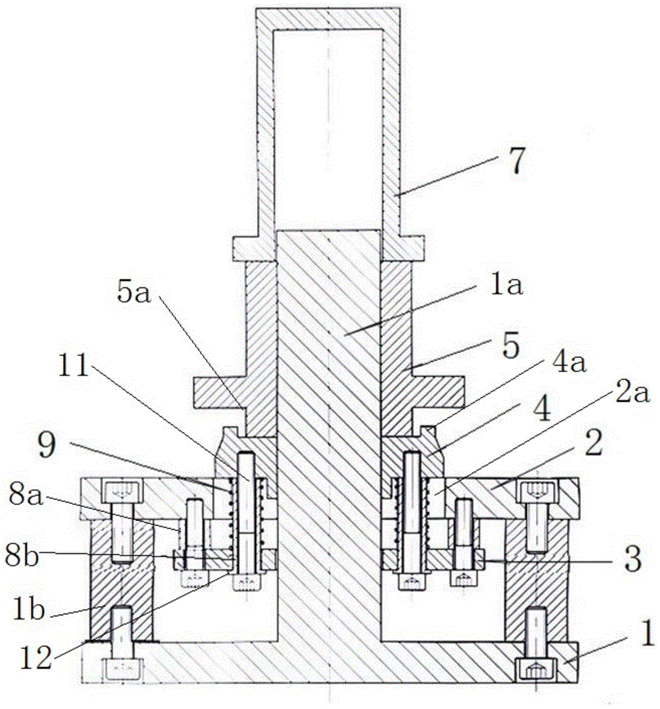
Example 1: as shown in fig. 1 and 2. The invention relates to an oil seal assembling device for engineering machinery, which comprises a base 1, a supporting plate 3, a template 2, a material ejecting plate 4, a material pressing sleeve 5, a pressing cylinder 7 and the like.
The base 1 comprises a bottom plate, a pillar 1a fixed in the middle of the bottom plate, equal-height balance supports 1b fixed on two opposite sides or the periphery of the bottom plate through screws and the like. The supporting plate 3 is sleeved on the support 1a through a middle hole, and the template 2 is positioned below the supporting plate 3 of the template 2, sleeved on the support 1a through the middle hole and fixedly connected to the equal-height balance support 1b through a corresponding screw.
The ejector plate 4 is positioned on the upper part of the template 2 and sleeved on the pillar 1 a. A plurality of fixed equal-height sleeves 8a are arranged and fixed between the support plate 3 and the formwork 2 by screws (connecting means) or the like.
A plurality of follow-up equal-height sleeves 8b are arranged between the supporting plate 3 and the ejector plate 4 through screws (corresponding connecting devices) 11, the follow-up equal-height sleeves 8b are movably arranged between the supporting plate 3 and the lower wall surface of the ejector plate 4 through guide holes of the supporting plate 3 and accommodating through holes of the templates 2, the planar convex ring 12 is fixedly connected to the lower end of the follow-up equal-height sleeves 8b, and the follow-up equal-height sleeves 8b are fixedly connected to the ejector plate 4 through the follow-up screws (corresponding connecting devices) 11 in a threaded manner from the lower planar wall surface of the planar convex ring 12. The follow-up equal-height sleeve 8b is sleeved with a jacking spring 9 positioned between the upper wall surface of the supporting plate 2 and the lower wall surface of the jacking plate 4 through the accommodating through hole of the template 2.
The follow-up screw 11 and the follow-up equal-height sleeve 8b can be lifted up and down along with the ejector plate under the action of the ejector spring, the upper plane wall surface of the plane convex ring 12 can be in parallel contact with or separated from the lower plane wall surface of the supporting plate, and the separable distance between the plane convex ring 12 and the supporting plate is about the lifting stroke of the ejector plate. The template 2 is provided with an avoidance cavity 2a formed by a middle hole thereof so as to provide an up-and-down running channel of the ejector plate.
The ejector plate 4 corresponds to a mounting hole of the corresponding workpiece 10 to position the workpiece 10. The outer side of the upper wall surface of the ejector plate 4 is provided with a convex ring table 4 a. The ejector plate 4 supports and cooperates the corresponding part of the framework oil seal 6 through the convex ring 4 a.
The material pressing sleeve 5 is positioned on the upper portion of the ejector plate 4 and sleeved on the support, the lower end of the material pressing sleeve 5 is provided with a step end face 5b, and the ejector plate 4 positions the corresponding framework oil seal 6 through the step end face 5 b. The pressing cylinder 7 is positioned on the upper part of the pressing sleeve 5 and sleeved on the support 1 a.
The supporting plate 3, the template 2 and the ejector plate 4 can be respectively annular. The pillar is a cylinder.
The engineering machinery oil seal assembling device is equipped for working:
positioning a workpiece: after the template, the ejector plate, the support plate and the like are mounted on the base through corresponding parallel self-supporting devices and the like, the workpiece 10 is sleeved and horizontally placed on the template from the support, and the workpiece is supported by the template. Meanwhile, the ejector plate is in a free ejection state under the action of the ejector spring, so that the ejector plate is sleeved in the mounting hole of the workpiece to position the workpiece.
Positioning a framework oil seal: and sleeving the framework oil seal 6 at the lower end of the material pressing sleeve through the step end face of the material pressing sleeve, and matching the material pressing sleeve with the inner hole of the framework oil seal to position the framework oil seal.
Combination of a framework oil seal and a workpiece: the pressing sleeve with the framework oil seal is sleeved from the support, and the pressing sleeve contacts the ejector plate, but at the moment, under the supporting force of the ejector spring, the framework oil seal is not in contact with the workpiece, and the ejector plate plays a role in auxiliary support for the framework oil seal.
The method comprises the following steps: and (3) arranging the pressing barrel on the material ejecting sleeve through the support, starting the press to press the pressing barrel downwards, pushing the material pressing sleeve by the pressing barrel, pushing the material ejecting plate by the material pressing sleeve, pressing the framework oil seal into the workpiece, and finishing the equipment. In the working process of the equipment, the ejector plate always plays a corresponding auxiliary supporting role.
Example 2: as shown in fig. 3. The parallel self-service supporting device arranged between the supporting plate and the template comprises an ejector plate fixing equal-height sleeve 8ba, the lower end of the ejector plate fixing equal-height sleeve 8ba is positioned on the upper wall surface of the supporting plate 3 and supported on the supporting plate, the upper end of the ejector plate fixing equal-height sleeve 8ba is positioned on the lower wall surface of the ejector plate 4 and abuts against the ejector plate, a lower section thread section 11a of a screw 11 is in threaded connection with a thread section of the inner wall surface of the ejector plate fixing equal-height sleeve 8ba and fixed, and an upper section of the screw 11 is a non-threaded section 11b and matched with a corresponding blind hole of the ejector plate 4 and can guide the up-and-down movement of the ejector plate. The remaining structure and corresponding method of assembly of this example may be similar to the above described embodiments.