CN1136811C - Suction device accessory, E. G. for damp surface cleaning - Google Patents
Suction device accessory, E. G. for damp surface cleaning Download PDFInfo
- Publication number
- CN1136811C CN1136811C CNB971807337A CN97180733A CN1136811C CN 1136811 C CN1136811 C CN 1136811C CN B971807337 A CNB971807337 A CN B971807337A CN 97180733 A CN97180733 A CN 97180733A CN 1136811 C CN1136811 C CN 1136811C
- Authority
- CN
- China
- Prior art keywords
- locking
- suction device
- valve
- device attachment
- suction
- Prior art date
- Legal status (The legal status is an assumption and is not a legal conclusion. Google has not performed a legal analysis and makes no representation as to the accuracy of the status listed.)
- Expired - Fee Related
Links
Images


Classifications
-
- A—HUMAN NECESSITIES
- A47—FURNITURE; DOMESTIC ARTICLES OR APPLIANCES; COFFEE MILLS; SPICE MILLS; SUCTION CLEANERS IN GENERAL
- A47L—DOMESTIC WASHING OR CLEANING; SUCTION CLEANERS IN GENERAL
- A47L1/00—Cleaning windows
- A47L1/06—Hand implements
- A47L1/08—Hand implements with provision for supplying liquids, e.g. cleaning agents
-
- A—HUMAN NECESSITIES
- A47—FURNITURE; DOMESTIC ARTICLES OR APPLIANCES; COFFEE MILLS; SPICE MILLS; SUCTION CLEANERS IN GENERAL
- A47L—DOMESTIC WASHING OR CLEANING; SUCTION CLEANERS IN GENERAL
- A47L11/00—Machines for cleaning floors, carpets, furniture, walls, or wall coverings
- A47L11/38—Machines, specially adapted for cleaning walls, ceilings, roofs, or the like
-
- A—HUMAN NECESSITIES
- A47—FURNITURE; DOMESTIC ARTICLES OR APPLIANCES; COFFEE MILLS; SPICE MILLS; SUCTION CLEANERS IN GENERAL
- A47L—DOMESTIC WASHING OR CLEANING; SUCTION CLEANERS IN GENERAL
- A47L11/00—Machines for cleaning floors, carpets, furniture, walls, or wall coverings
- A47L11/40—Parts or details of machines not provided for in groups A47L11/02 - A47L11/38, or not restricted to one of these groups, e.g. handles, arrangements of switches, skirts, buffers, levers
-
- A—HUMAN NECESSITIES
- A47—FURNITURE; DOMESTIC ARTICLES OR APPLIANCES; COFFEE MILLS; SPICE MILLS; SUCTION CLEANERS IN GENERAL
- A47L—DOMESTIC WASHING OR CLEANING; SUCTION CLEANERS IN GENERAL
- A47L11/00—Machines for cleaning floors, carpets, furniture, walls, or wall coverings
- A47L11/40—Parts or details of machines not provided for in groups A47L11/02 - A47L11/38, or not restricted to one of these groups, e.g. handles, arrangements of switches, skirts, buffers, levers
- A47L11/408—Means for supplying cleaning or surface treating agents
- A47L11/4088—Supply pumps; Spraying devices; Supply conduits
-
- A—HUMAN NECESSITIES
- A47—FURNITURE; DOMESTIC ARTICLES OR APPLIANCES; COFFEE MILLS; SPICE MILLS; SUCTION CLEANERS IN GENERAL
- A47L—DOMESTIC WASHING OR CLEANING; SUCTION CLEANERS IN GENERAL
- A47L7/00—Suction cleaners adapted for additional purposes; Tables with suction openings for cleaning purposes; Containers for cleaning articles by suction; Suction cleaners adapted to cleaning of brushes; Suction cleaners adapted to taking-up liquids
- A47L7/0004—Suction cleaners adapted to take up liquids, e.g. wet or dry vacuum cleaners
-
- A—HUMAN NECESSITIES
- A47—FURNITURE; DOMESTIC ARTICLES OR APPLIANCES; COFFEE MILLS; SPICE MILLS; SUCTION CLEANERS IN GENERAL
- A47L—DOMESTIC WASHING OR CLEANING; SUCTION CLEANERS IN GENERAL
- A47L7/00—Suction cleaners adapted for additional purposes; Tables with suction openings for cleaning purposes; Containers for cleaning articles by suction; Suction cleaners adapted to cleaning of brushes; Suction cleaners adapted to taking-up liquids
- A47L7/0004—Suction cleaners adapted to take up liquids, e.g. wet or dry vacuum cleaners
- A47L7/0009—Suction cleaners adapted to take up liquids, e.g. wet or dry vacuum cleaners with means mounted on the nozzle; nozzles specially adapted for the recovery of liquid
-
- F—MECHANICAL ENGINEERING; LIGHTING; HEATING; WEAPONS; BLASTING
- F16—ENGINEERING ELEMENTS AND UNITS; GENERAL MEASURES FOR PRODUCING AND MAINTAINING EFFECTIVE FUNCTIONING OF MACHINES OR INSTALLATIONS; THERMAL INSULATION IN GENERAL
- F16K—VALVES; TAPS; COCKS; ACTUATING-FLOATS; DEVICES FOR VENTING OR AERATING
- F16K15/00—Check valves
- F16K15/02—Check valves with guided rigid valve members
- F16K15/04—Check valves with guided rigid valve members shaped as balls
-
- F—MECHANICAL ENGINEERING; LIGHTING; HEATING; WEAPONS; BLASTING
- F16—ENGINEERING ELEMENTS AND UNITS; GENERAL MEASURES FOR PRODUCING AND MAINTAINING EFFECTIVE FUNCTIONING OF MACHINES OR INSTALLATIONS; THERMAL INSULATION IN GENERAL
- F16K—VALVES; TAPS; COCKS; ACTUATING-FLOATS; DEVICES FOR VENTING OR AERATING
- F16K15/00—Check valves
- F16K15/02—Check valves with guided rigid valve members
- F16K15/06—Check valves with guided rigid valve members with guided stems
- F16K15/063—Check valves with guided rigid valve members with guided stems the valve being loaded by a spring
Landscapes
- General Engineering & Computer Science (AREA)
- Engineering & Computer Science (AREA)
- Mechanical Engineering (AREA)
- Self-Closing Valves And Venting Or Aerating Valves (AREA)
- Nozzles For Electric Vacuum Cleaners (AREA)
- Orthopedics, Nursing, And Contraception (AREA)
- Mechanically-Actuated Valves (AREA)
- Detergent Compositions (AREA)
- Adornments (AREA)
- Massaging Devices (AREA)
- Telephone Function (AREA)
- Cleaning Implements For Floors, Carpets, Furniture, Walls, And The Like (AREA)
- Lift Valve (AREA)
- Filters For Electric Vacuum Cleaners (AREA)
- Cleaning In General (AREA)
Abstract
Description
技术领域technical field
本发明涉及一种抽吸装置的附件,它例如用于湿清洗平面,特别是垂直平面,其具有一抽吸通道,在抽吸通道内设置一通过水汽冲击触发的阀门。The invention relates to an accessory for a suction device, for example for wet cleaning surfaces, in particular vertical surfaces, which has a suction channel in which a valve is arranged which is triggered by the impingement of water vapor.
背景技术Background technique
DE-A119611371中公开了这样一种抽吸装置附件,它可以对平面,例如玻璃窗进行水洗。在清洗过程中将一种洗涤液洒在平面上,并将洗涤液与其所吸收的污物颗粒一同吸走。吸走的污水收集在一设置在抽吸通道内的水箱内。公知在水箱后面装有安全装置,它切断抽吸气流。当水箱后面的抽吸气流内的剩余湿度超过一预定值时,一可触发的阀门封闭抽吸通道,这是为了避免装有抽吸装置附件的吸尘器内的马达损坏。例如,在此可以采用触发用于测量流动流体密度的不同物理效应的装置。可以利用施加在一装在流动横截面上的部件上或施加在流动的横截面变化处的力。利用动压头也是公知的。为此可以将其用于包括一种液体相的两相流体流动中,以便改变材料的特性,例如纸板等的耐撕裂强度。公知的构成密度传感器的阀门受流速影响很大,并且易于受到污染。而且由于需要大量部件,在技术上也是昂贵的。Such a kind of suction device attachment is disclosed among DE-A119611371, and it can carry out washing to flat surface, for example glass window. During the cleaning process, a washing liquid is sprinkled on the surface and sucks up the washing liquid together with the dirt particles it has absorbed. The sucked sewage is collected in a water tank arranged in the suction channel. It is known to have a safety device behind the tank which cuts off the suction flow. When the residual humidity in the suction air flow behind the water tank exceeds a predetermined value, a triggerable valve closes the suction channel, in order to avoid damage to the motor in vacuum cleaners equipped with suction attachments. For example, means for triggering different physical effects for measuring the density of the flowing fluid may be employed here. Forces applied to a component mounted on the cross-section of the flow or to a change in cross-section of the flow can be used. It is also known to use a dynamic head. For this purpose it can be used in two-phase fluid flows comprising a liquid phase in order to modify the properties of the material, for example the tear strength of cardboard or the like. Known valves constituting density sensors are highly dependent on flow velocity and are prone to contamination. It is also technically expensive due to the large number of components required.
此外,国际专利申请WO 94/08502公开了一种与真空抽吸装置的抽吸导管相连的空气/液体分离装置。其中,所采用的阀按照漂浮原理可被触发。一旦容器中的水位超过一定的高度,所述阀门就被触发推开或者说有一条流动通道向该阀敞开。由此流入的不含水的流体之后会使阀移动到关闭位置。Furthermore, International Patent Application WO 94/08502 discloses an air/liquid separation device connected to a suction conduit of a vacuum suction device. In this case, the valves used can be activated according to the floating principle. As soon as the water level in the container exceeds a certain height, the valve is triggered and pushed open or a flow channel is opened to the valve. The resulting inflow of non-aqueous fluid then moves the valve to the closed position.
发明内容Contents of the invention
关于上述现有技术,本发明着手解决的一个技术问题在于提供一种抽吸装置附件,其在抽吸通道内设置一个由水汽冲击触发的阀门,这种抽吸装置附件在阀门触发方面具有突出的工作可靠性。With regard to the above-mentioned prior art, a technical problem to be solved by the present invention is to provide a suction device attachment, which is provided with a valve triggered by the impact of water vapor in the suction channel. work reliability.
这一问题首先通过一种抽吸装置的抽吸装置附件来解决,其具有一可流过一抽吸空气流的抽吸通道,其中,在该抽吸通道内设有一可触发的阀门,该阀门由一个可移动的球形或半球形或球壳形的闭锁体构成,当该闭锁体为半球形或球壳形时,其圆表面正对着抽吸空气流的流入方向,所述闭锁体被抽吸空气流绕流并被构造和设置成,使得当抽吸空气流与一个更高密度的质量流相叠加时,形成辅助的脉动流使闭锁体从其构成阀门打开位置的平衡位置移动到一个密闭的阀门闭合位置,进而导致抽吸空气流中断。This problem is firstly solved by a suction device attachment of a suction device, which has a suction channel through which a suction air flow can flow, wherein a triggerable valve is arranged in the suction channel, the The valve is composed of a movable spherical or hemispherical or spherical-shell-shaped locking body. When the locking body is hemispherical or spherical-shell-shaped, its circular surface is facing the inflow direction of the suction air flow. The locking body The suction air flow surrounds and is constructed and arranged so that when the suction air flow is superimposed on a higher density mass flow, an auxiliary pulsating flow is formed to move the closing body from its equilibrium position constituting the valve open position to a tight valve closed position, resulting in interruption of suction air flow.
按照本发明,待测量液体流向该可移动闭锁体。通过抽吸通道在所构成的阀门的区域内一种特殊的横断面形成闭锁体绕流,它使得所作用的轴向力将闭锁体保持在一种平衡状态。这些力例如为重力、由动压或静压得到的力、摩擦力和动量或冲击力。如果正常的来流被一种密度更高的质量流所叠加,则附加动量将闭锁体从其构成阀门开启位置的平衡状态转移到一种阀门关闭位置。如果质量流产生的动量很小,则闭锁体的偏转也相应地很小,从而使闭锁体保持在出流位置或阀门开启的位置或其附近。如果质量流超过一预定的阀值,则闭锁体不再保持在这种平衡状态,而是迅速移动到阀门关闭位置,这样,闭锁体就将这种体积流关断。因此对开关点作如下明确定义:第一开关点,这时闭锁体处于体积流完全通过的位置,第二开关点,这时闭锁体处于完全闭合的位置。这样构成的阀门不易受到污染,并且与流速、温度和空气湿度无关。此外,按照本发明的这种设计得到一种简单而成本有利并且功能可靠的结构。按照本发明的阀门不易受到大约每分钟0.5ml这样小的水体积流的影响。按照本发明的设计还可以得到一种使闭锁体平衡的特殊的绕流形状。闭锁体受流速影响很小而很容易受到两相流中密度变化的影响,可以看作是特别有利的。在此已证明阀门不易出现故障,因为在阀门装置中,只设置了一个移动部件,即闭锁体。这种阀门具有良好的时间响应特性,特别是具有一种数字式开关性能,其中的流动压力损失很小。为此建议以一球体作为闭锁体。在这方面还规定闭锁体基本上只可垂直运动。为了预调系统作出反应的阈值,可以调节距阀门开孔的一静止位置。为此,可以例如通过抽吸通道内的一轴向止挡件调节闭锁体的轴向位置。还可以通过这种调节机构实现系统的外部强制触发。为了将闭锁体保持在流动横截面的一中央轴线上,规定将闭锁体设置在一个使绕流路径保持通畅的笼子中。这个笼子是这样设计的,即,所施加的轴向力由此能使闭锁体保持在一种平衡状态。为此进一步建议,所述笼子具有向内凸起的筋条,这些筋条留出一与闭锁体的横截面相匹配的自由空间或大于它的自由空间。为了识别一种在一流动通道内迅速移动的液体相,以便提供一机械的开关信号,进一步建议闭锁体由弹簧支撑在开启位置。在此利用在闭锁体上出现的第二流体相的动量和由流体绕流的闭锁体的阻力的变化。这样在一恒定速度下,空气中的阻力大于水中的阻力。如果在闭锁体上出现密度更大的第二流体相,则闭锁体克服弹簧力移动到阀门关闭的位置。其中弹簧力被设计成,只要两相流体的密度有很小的变化,阀门即行关闭。因此,阀闭的开关灵敏度很高。为此还进一步建议将闭锁体设计成盘形。优选一种实施方式是将闭锁体设计成半球形。在此,闭锁体的盘形或半球形表面迎着来流方向。还进一步建议弹簧支撑在阀门开孔的区域。在此,一种优选的实施形式是阀门支撑在阀门开启区域的中央。例如可以这样来设置,即,将弹簧设置在一引导闭锁体的导板的中央。优选将导板设置在阀门开启区域抽吸通道的轴向上。弹簧一端支撑在导板上,另一端支撑在闭锁体背面,它将闭锁体保持在一静止位置,该静止位置限定了阀门的开启位置。当流量加大时,闭锁体克服弹簧力,朝阀门开启孔的方向移动,并以环形密封的方式将其关闭,以便切断抽吸气流。还可以例如用电子装置检测这种阀门关闭位置,以切断抽吸装置的电机。According to the invention, the liquid to be measured flows towards the movable blocking body. A special cross-section of the suction channel in the region of the formed valve forms a flow around the closing body, which causes the axial forces acting to keep the closing body in a state of equilibrium. These forces are, for example, gravity, forces resulting from dynamic or static pressure, friction and momentum or impact. If the normal incoming flow is superimposed by a denser mass flow, the additional momentum transfers the blocking body from its equilibrium state forming a valve-opening position to a valve-closing position. If the momentum generated by the mass flow is low, the deflection of the closing body is correspondingly low, so that the closing body remains in or near the outflow position or valve-opening position. If the mass flow exceeds a predetermined threshold value, the closing body no longer remains in this equilibrium state, but moves rapidly into the valve closed position, so that the closing body shuts off the volume flow. The switching points are therefore clearly defined as follows: a first switching point, in which the closing body is in the position in which the volume flow completely passes through, and a second switching point, in which the closing body is in the fully closed position. A valve constructed in this way is less susceptible to contamination and is independent of flow rate, temperature and air humidity. Furthermore, the design according to the invention results in a simple, cost-effective and functionally reliable construction. The valve according to the invention is not susceptible to water volume flows as small as about 0.5 ml per minute. According to the design according to the invention, a special flow-around shape which balances the blocking body can also be obtained. Locking bodies which are less affected by flow velocity and are more easily affected by density changes in the two-phase flow can be seen as particularly advantageous. In this case, the valve has proven to be less prone to failure, since only one moving part, the closing body, is provided in the valve arrangement. This valve has good time response characteristics, especially a digital switching performance, in which the flow pressure loss is very small. For this reason it is proposed to use a sphere as the locking body. It is also provided here that the locking body is essentially only movable vertically. In order to preset the threshold at which the system reacts, a rest position from the valve opening can be adjusted. For this purpose, the axial position of the closure body can be adjusted, for example, via an axial stop in the suction channel. An external forced triggering of the system is also possible via this adjustment mechanism. In order to keep the closing body on a central axis of the flow cross-section, it is provided that the closing body is arranged in a cage which keeps the flow path around it free. The cage is designed in such a way that the applied axial force thus keeps the locking body in a state of equilibrium. For this purpose it is further proposed that the cage has inwardly protruding ribs which leave a free space which matches the cross section of the locking body or is larger than this. In order to detect a rapidly moving liquid phase in a flow channel in order to provide a mechanical switching signal, it is further proposed that the closing body is spring-loaded in the open position. The momentum of the second fluid phase present at the closing body and the change in the resistance of the closing body, which is flowed by the fluid around it, are used here. Thus at a constant speed, the resistance in the air is greater than the resistance in the water. If a second, denser fluid phase is present on the closing body, the closing body moves against the spring force into the valve-closed position. The spring force is designed to close the valve as long as there is a small change in the density of the two-phase fluid. Therefore, the switching sensitivity of the valve closure is high. For this purpose it is further proposed to design the locking body in the form of a disk. A preferred embodiment is to design the locking body in a hemispherical shape. Here, the disk-shaped or hemispherical surface of the closure body faces the direction of the incoming flow. It is further proposed that the spring is supported in the region of the valve opening. In a preferred embodiment, the valve is supported centrally in the valve opening area. For example, it can be provided that the spring is arranged centrally on a guide plate which guides the locking body. Preferably, the guide plate is arranged in the axial direction of the suction channel in the valve opening area. One end of the spring is supported on the guide plate and the other end is supported on the back of the blocking body, which keeps the blocking body in a rest position which defines the open position of the valve. When the flow rate increases, the blocking body overcomes the spring force, moves toward the opening hole of the valve, and closes it in an annular sealing manner, so as to cut off the suction flow. It is also possible, for example, to detect such a closed valve position electronically in order to switch off the motor of the suction device.
本发明所要解决的技术问题还可通过另一种类型的抽吸装置附件来解决,其具有一可流过一种质量流的抽吸通道,在该抽吸通道内设有一通过水汽冲击可触发的阀门,其中闭锁体通过弹簧预紧力处于闭合位置,它通过一锁定元件可保持在开启位置,该锁定元件受水汽冲击可被触发,为了与位置无关地识别在一流动通道中的流体相,以便提供一机械的开关信号,本发明建议,该锁定元件支撑一沿径向可偏离,使闭锁体的移动路径通畅的止动爪。The technical problem to be solved by the present invention can also be solved by another type of suction device attachment, which has a suction channel through which a mass flow can flow, in which a suction channel can be triggered by the impact of water vapor valve, in which the closing body is in the closed position by spring pretension, it can be held in the open position by a locking element, which can be triggered by the impact of water vapor, in order to identify the fluid phase in a flow channel independently of the position , in order to provide a mechanical switching signal, the invention proposes that the locking element supports a radially deflectable pawl, so that the movement path of the locking body is unobstructed.
本发明的上述技术解决方案基于这样的想法,即,采用一种吸收液体的材料,例如海绵等,其机械和/或几何特性在与一种液体接触时发生变化。按照本发明的锁定元件以一种流体吸收材料的形式构成,其位于流体流动通道的区域内。这种材料的机械和/或几何变化可以发生在任何方向上,例如在流动方向上,与此流动方向相反的方向上,以及垂直于流动方向的方向上或者与之发生扭转的方向上。这种吸收液体的锁定元件支撑闭锁体一侧的一止动爪,使得该闭锁体保持在阀门开启的位置上。弹簧使闭锁体朝阀门关闭位置方向被预紧。释放闭锁体的移动通道的锁定元件的止动爪例如可以设计成板簧等形式,在未受水汽冲击的状态下,它通过锁定元件被保持在一个将闭锁体锁定在阀门开启位置的位置上。随着吸入液体的增加,锁定元件的材料软化,从而使闭锁体越出止动爪的区域,由于其板簧式设计以及不再受到锁定元件足够的径向支撑,该止动爪会发生偏离。该闭锁体在弹簧的作用下自动移动到阀门关闭的位置。在本发明的另一改进设计中规定,闭锁体具有一与止动爪共同作用的移动套筒。该移动套筒可以通过一穿过阀门开口的阀杆与闭锁体连接。移动套筒优选包围着锁定元件,在阀门开启位置,它压在由锁定元件支撑着的止动爪上。按照这种实施方式,优选一种布置,其中所述阀门开口从抽吸通道的轴向上看位于锁定件与闭锁体之间。为了使闭锁体摩擦(非啮合)固定在阀门开启位置,规定在移动套筒上设置一闭锁凸块,以便与止动爪共同作用。闭锁凸块和止动爪可以带有静止时彼此靠在一起的倾斜面,以便当锁定元件软化时止动爪容易通过受弹簧力作用的闭锁凸块而偏离。还建议闭锁凸块设计成沿径向向内凸入,相应地也可优选将止动爪设计成径向向外凸出。如上所述,止动爪可以是弹性的。可以以如下的方式对其利用,在止动爪越过设置在套筒上的闭锁凸块之后,后者与重新弹回到初始位置上的止动爪后啮合,以保证阀门的关闭位置。在本发明的一有利的实施形式中规定,锁定元件设计成一圆柱段,并留出一内部流动路径。在此优选这样一种布置,即,流体从优选为海绵式的锁定元件的内侧沿径向向外流出。在具有一液体相的流体流过锁定元件时,锁定元件发生机械和/或几何变化。这样锁定元件可以随着水份的冲击而软化。在静止位置通过锁定元件支撑的止动爪此后可以发生偏离。在本发明的一有利的改进设计中闭锁体装在一移动套筒内,锁定元件闭锁地嵌入移动套筒的移动路径中。为此还可以规定,锁定元件由一种通过一海绵体支撑的径向凸起的闭锁凸块构成。后者例如在海绵体软化的情况下可以释放优选受弹簧支撑的闭锁体,以便使其移动到阀门关闭的位置。在此已证明比较有利的是,闭锁凸块在突入移动套筒内的一凹口中的情况下将移动套筒锁定。这种布置可以在一种实施形式下选择,在该实施方式中,锁定元件一材料的机械和几何变化发生在流动方向上,并且在流动方向上的阀门开口设置在闭锁体的后面。为了使闭锁体例如通过手动重新回到释放阀门开口的静止位置,规定在移动套筒下侧的闭锁凹口具有一迎着移动方向的控制曲线,以便在移动套筒返回到阀门开启的位置时调整闭锁凸块。通过移动套筒和装在其内的闭锁体的返回移动,闭锁凸块重新回到其将移动套筒闭锁的位置。但是这种动作的条件是锁定元件一材料首先发生返回其初始的或者说干燥和硬化的形状。最后建议,海绵体具有一基本上作用在挡爪中央的闭锁区域。在该闭锁区域软化以后,闭锁凸块可以按照先前描述的方法偏离。前述具有一通过水汽冲击而触发的锁定元件的实施形式与位置无关地识别一种液体相,并且其结构空间最小。这种实施形式还在很大的开关区域内提供一种机械开关信号。The above-mentioned technical solution of the invention is based on the idea of using a liquid-absorbing material, such as a sponge or the like, whose mechanical and/or geometrical properties change when in contact with a liquid. The locking element according to the invention is formed in the form of a fluid-absorbent material which is located in the region of the fluid flow channel. The mechanical and/or geometrical changes of this material can take place in any direction, for example in the flow direction, in the direction opposite to the flow direction, and in a direction perpendicular to the flow direction or in a twisted direction thereto. This fluid-absorbing locking element supports a locking pawl on one side of the closing body, so that the closing body is held in the valve-open position. The spring pretensions the closing body towards the closed position of the valve. The stop pawl of the locking element that releases the movement channel of the locking body can be designed, for example, as a leaf spring, etc., and it is held in a position that locks the locking body in the valve opening position by the locking element when it is not impacted by water vapor. . As more liquid is sucked in, the material of the locking element softens so that the locking body moves beyond the area of the pawl, which deflects due to its leaf spring design and is no longer sufficiently radially supported by the locking element . The locking body automatically moves to the position where the valve is closed under the action of the spring. In a further refinement of the invention it is provided that the locking body has a displacement sleeve interacting with the locking pawl. The displacement sleeve can be connected to the closing body via a valve stem passing through the valve opening. The moving sleeve preferably surrounds the locking element, which, in the valve open position, presses against a pawl supported by the locking element. According to this embodiment, an arrangement is preferred in which the valve opening, viewed in the axial direction of the suction channel, is located between the locking part and the closing body. In order to fix the locking body frictionally (non-engaging) in the open position of the valve, it is provided that a locking projection is arranged on the displacement sleeve in order to cooperate with the locking pawl. The locking lug and the pawl can have inclined surfaces which lie against each other at rest, so that the pawl is easily deflected by the locking lug under spring force when the locking element softens. It is also proposed that the locking lugs be designed radially inwardly, and that correspondingly preferably the locking pawls are also designed radially outwardly. As mentioned above, the pawl may be elastic. It can be used in such a way that after the locking pawl has passed over the locking cam arranged on the sleeve, the latter engages with the locking pawl which springs back into the original position to ensure the closed position of the valve. In an advantageous embodiment of the invention it is provided that the locking element is designed as a cylindrical section and leaves an internal flow path. Preference is given here to an arrangement in which the fluid flows radially outward from the inner side of the preferably sponge-like locking element. When a fluid having a liquid phase flows through the locking element, the locking element undergoes a mechanical and/or geometric change. This allows the locking element to soften with the impact of moisture. The pawl supported by the locking element in the rest position can then be deflected. In an advantageous further development of the invention, the locking body is accommodated in a displacement sleeve, the locking element engaging in a locking manner in the displacement path of the displacement sleeve. It can also be provided for this purpose that the locking element is formed as a radially protruding locking cam supported by a sponge body. The latter can release the preferably spring-loaded locking body, for example, in the case of softening of the sponge body, in order to move it into the valve-closed position. It has proven to be advantageous here if the locking cam locks the displacement sleeve when it projects into a recess in the displacement sleeve. This arrangement can be selected in an embodiment in which a mechanical and geometric change of the material of the locking element takes place in the flow direction and the valve opening in the flow direction is arranged behind the closing body. In order to make the locking body return to the rest position of the release valve opening, for example manually, it is provided that the locking recess on the underside of the moving sleeve has a control curve facing the direction of movement, so that when the moving sleeve returns to the valve-opening position Adjust the locking tabs. Due to the return movement of the moving sleeve and the locking body accommodated therein, the locking lug returns to the position in which it locks the moving sleeve. A condition for this action, however, is that the locking element—the material—first returns to its original or dried and hardened shape. Finally, it is proposed that the sponge body has a locking region which acts essentially centrally on the pawl. After the locking region has softened, the locking cams can be deflected in the manner described above. The aforementioned embodiment with a locking element triggered by the impact of water vapor detects a liquid phase independently of its position and requires minimal installation space. This embodiment also provides a mechanical switching signal over a large switching area.
附图说明Description of drawings
下面结合附图所示几个实施例详细描述本发明,附图中:Describe the present invention in detail below in conjunction with several embodiments shown in the accompanying drawings, in the accompanying drawings:
图1示出一用于湿清洗平面的抽吸装置附件,它通过一吸水(气)软管与一吸尘器连接;Fig. 1 shows a suction device attachment for wet cleaning plane, which is connected with a vacuum cleaner by a water suction (air) hose;
图2简要示出第一实施形式的阀门结构的纵剖面图,图示的阀门处于开启位置;Fig. 2 schematically shows a longitudinal sectional view of the valve structure of the first embodiment, the valve shown in the illustration is in an open position;
图3示出沿图2中的III-III线的截面;Fig. 3 shows a section along line III-III in Fig. 2;
图4是与图2对应的一示图,图中示出阀门处于关闭位置;Figure 4 is a diagram corresponding to Figure 2, showing the valve in a closed position;
图5示出阀门装置的第二种实施形式,图中示出阀门处于开启位置;Figure 5 shows a second embodiment of the valve device, showing the valve in an open position;
图6是与图5对应的一示图,图中示出阀门处于关闭位置;Figure 6 is a diagram corresponding to Figure 5, showing the valve in a closed position;
图7示出沿图6中的VII-VII线的截面;Figure 7 shows a section along line VII-VII in Figure 6;
图8示出阀门装置的第三种实施形式,图中示出的阀门处于开启状态;Fig. 8 shows the third embodiment of the valve device, the valve shown in the figure is in an open state;
图9示出图8所示的阀门装置在阀门关闭过程中的一中间位置;Fig. 9 shows an intermediate position of the valve device shown in Fig. 8 during valve closing;
图10示出图8所示的阀门装置的阀门处于关闭位置;Figure 10 shows the valve of the valve arrangement shown in Figure 8 in a closed position;
图11是阀门装置的第四种实施形式的一纵剖面图,图中示出的阀门处于开启的位置;Fig. 11 is a longitudinal sectional view of a fourth embodiment of the valve device, the valve shown in the figure being in an open position;
图12是阀门装置的第五种实施形式的一纵剖面图,图中示出阀门处于开启位置;Fig. 12 is a longitudinal sectional view of a fifth embodiment of the valve device, showing the valve in an open position;
图13是与图12对应的一剖面图,图中示出阀门关闭过程中的一中间位置;Figure 13 is a sectional view corresponding to Figure 12, showing an intermediate position during valve closing;
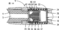
图14示出图12所示的阀门装置的阀门处于关闭位置。Figure 14 shows the valve of the valve arrangement shown in Figure 12 in a closed position.
具体实施方式Detailed ways
首先参照图1来描述一用于湿清洗平面,特别是垂直平面的抽吸装置附件1。该抽吸装置通过一抽吸软管2与一地板吸尘器3流动连通。通过抽吸装置附件1,以一种公知的方法将一种洗涤液洒在需清洗的平面上,并随即将其与所吸收的污物颗粒一起吸起。为此,抽吸装置附件1在构成附件装置的一抽吸通道5内带有一污水收集箱4,该收集箱在图1中没有详细示出。在收集箱4中所抽出的液体被沉积分离。A suction device attachment 1 for wet cleaning flat surfaces, in particular vertical surfaces, will be described first with reference to FIG. 1 . The suction device is in flow communication with a floor cleaner 3 via a
沿流动方向R在收集箱4的后面设置一通过水汽冲击可触发的阀门V,当气流中的剩余湿度超过一预定值时,阀门V关闭抽吸通道,从而截断气流。Arranged behind the collecting
在图2至4中示出阀门V的第一实施形式,其基本上具有一构成闭锁体6的球体7。该球体沿抽吸通道5的轴向可移动地设置在相对于抽吸通道5横截面扩大的区域内。在该横截面扩大的与抽吸通道5同轴的区域8内设置了沿抽吸通道5的轴向延伸的、分布在内壁上并向内凸起的筋条9,以形成一笼子10。在图示实施例中,按照图3所示的横截面,安装了四个径向设置的筋条9,留出了大致与球形闭锁体6横截面相匹配的自由空间11。FIGS. 2 to 4 show a first embodiment of a valve V which essentially has a ball 7 forming the
因此,闭锁体6设置在一保留了绕流通路的笼子10内。Therefore, the blocking
通过相对于抽吸通道5扩大了的圆柱形的区域8构成了抽吸气流穿过的出入口,这些区域的开口直径选择得比球形闭锁体6的直径小。The openings through which the suction flow passes are formed by cylindrical regions 8 enlarged relative to the
在入口12的区域内设置一伸入抽吸通道5的板条13,其支撑着一轴向的可调节止挡芯轴14。借助于该止挡可以调节闭锁体6的轴向位置,该位置与和入口12相对的阀门开口15的位置有关。In the region of the inlet opening 12 there is provided a web 13 protruding into the
待测流体(箭头a)在工作时流过旋转对称的闭锁体6。通过扩大的区域8的横截面的这种特殊造型,由流过闭锁体6的绕流所形成的轴向作用力将闭锁体6保持在平衡状态。此外,板条13也将闭锁体6保持在流动横截面的中央轴线上。这种平衡状态在很大的范围内与流速无关。The fluid to be measured (arrow a) flows through the rotationally
通过借助于止挡芯轴14可进行的预调节可以调节系统根据其起作用的调节值。通过这种调节机构还可以从外部实现系统的强制触发。By means of the preadjustment possible by means of the stop spindle 14 , it is possible to adjust the setting value according to which the system acts. A forced triggering of the system can also be achieved from the outside by means of such an adjustment mechanism.
在图4中示出了阀V的闭合位置。在此,在通常的入流(箭头a)中叠加了一种高密度质量流(箭头b)。这一附加动量将闭锁体6从图4中虚线所示的平衡位置向阀门开口15的方向压。设计成球7的闭锁体6自此将阀门开口15密封,这导致抽吸气流的中断。The closed position of the valve V is shown in FIG. 4 . Here, a high-density mass flow (arrow b) is superimposed on the usual inflow (arrow a). This additional momentum presses the
如果质量流(箭头b)的动量很小,则相对于平衡位置的偏离也很小,闭锁体保持在起始位置附近,如图2所示。当质量流超过一预定的阈值时,则闭锁体不再能保持在图2所示的平衡位置,而是冲到设计为单向阀的阀门开口15。If the momentum of the mass flow (arrow b) is small, the deviation from the equilibrium position is also small and the blocking body remains close to the starting position, as shown in Figure 2. When the mass flow exceeds a predetermined threshold value, the closing body can no longer remain in the equilibrium position shown in FIG. 2 , but instead rushes into the
通过本发明的这种实施形式,阀门V具有一种数字化开关特性。With this embodiment of the invention, the valve V has a digital switching characteristic.
图5至7示出本发明的另一种实施方式。在此,在抽吸通道5中设置一个横截面减小的环形横壁16,它留有一个中央阀门开口15。一径向导板17(参见图7)穿过阀门开口15。5 to 7 show another embodiment of the invention. In this case, an annular
闭锁体6在这一实施形式中设计成半球形,其球形表面迎着流动方向R。这种闭锁体16还带有一旋转对称的中央凹槽18,该中央凹槽的横截面为梯形,它在闭锁体6的沿着流动方向R一侧的平面侧敞开,并由此构成一沿流动方向R并与抽吸通道5同轴的环形密封肩19,该密封肩的直径选择得大于阀门开口15的直径。In this embodiment, the
闭锁体6通过一轴向设置的阀杆20保持在横壁侧导板17的区域内。阀杆20的一端向内穿入阀门体6的头部,并穿透凹槽部分18,另一端穿过导板17的中心孔21。The
阀杆20在闭锁体6和导板17之间的区域内由一压簧22所围绕,该弹簧将闭锁体6支撑在其开启位置上。为了止挡限定,阀杆20在导板17的背向闭锁体6的一侧具有一横销23。The
在阀V的这种实施方式中,利用了第二流体相(箭头b)作用在闭锁体6上的冲击力和被流体绕流的闭锁体6的阻力变化。由于在速度不变的情况下,空气中的阻力大于水中的阻力,因此在对弹簧22相应设计后,阀门受第一流体相(箭头a)作用保持开启状态。而当冲击力超过弹簧22的阻力时,闭锁体6就向阀门开口15方向移动,进而以肩部19密封地贴靠在阀门开口15的周边区域上(为此参见图6)。此后抽吸气流被切断。这一实施形式的优点是无需使用电能或换能器,例如电机或者电磁铁。此外,利用这样设计的阀门V还可以检测几乎所有流体。In this embodiment of the valve V, the impact force of the second fluid phase (arrow b) acting on the
图8和10示出另一种实施形式的阀门V,其中弹簧将闭锁体6压在使阀门闭合的位置上,它通过一锁定元件24又被保持在开启位置。该锁定元件由一种流体吸收材料,例如一种海绵制成,并制成一圆筒段,其内留有一内部流动通路。FIGS. 8 and 10 show a further embodiment of a valve V in which a spring presses the
锁定元件24与抽吸通道5同轴设置,并支承在一罐形的套筒中。后者的直径比抽吸通道5的内径小。此外,这种端侧封闭的套筒25上还具有径向穿孔26,位于套筒内的锁定元件24从套筒的内壁覆盖住这些孔。自由截面的止动爪27在这些径向穿孔26中伸出套筒25,并可弹性向内偏转。The locking
一移动套筒28与套筒25搭接,其自由、开放端具有向内凸入的闭锁凸块29,用于将移动套筒28支撑在止动爪27上。移动套筒28在背向接触区域的端部区域内设计成一漏斗形,漏斗形的尖端支撑着一轴向对准的阀杆30。该阀杆30穿过一相对于抽吸通道5直径减小了的阀门开口15,并在其自由端支撑一盘形闭锁体6。A moving
一压簧31将闭锁体6,从而将通过阀杆30与其连接着的移动套筒28压在使阀门闭合的位置上,弹簧31的一端支撑在盘形闭锁体6上,另一端支撑在抽吸通道5内的一挡肩上。A
图8示出阀门V的一静止位置。在常规运行状态下,抽吸气流从内侧沿径向向外流过锁定元件24的径向孔26,以便随后绕流移动套筒28,并穿过阀门开口15流出阀门装置。此时,闭锁体6保持在阀门开启的位置,其条件是吸收流体的锁定元件24支撑止动爪27,使得通过弹簧31作用在止动爪27上的闭锁凸块29不能偏移。因此,移动套筒28通过闭锁凸块29摩擦地(非啮合)地支撑在止动爪27上。Figure 8 shows a rest position of the valve V. In the normal operating state, the suction air flow flows radially outward from the inside through the radial bore 26 of the locking
在一种流体相(箭头b)进入时,设计为检测元件的锁定元件24由于吸收了这些流体而软化。止动爪27失去了相应的支撑。因此,它通过受弹性作用的移动套筒28的闭锁凸块的作用径向向内偏移。止动爪27和闭锁凸块29设计成彼此以倾斜面相邻贴靠也促进了这种效果。When a fluid phase (arrow b) enters, the locking
在图9中示出阀门V在关闭过程中的一中间位置。此时,移动套筒28及闭锁体6被释放,以便使闭锁体6移动到图10所示的阀门闭合位置。An intermediate position of the valve V during closing is shown in FIG. 9 . At this time, the moving
在这一实施形式中利用了锁定元件一材料的机械和/或几何变化。这种变化可以在任何方向上发生,例如在流动方向上,在与之相反的方向上,或者与之相扭转的方向上。在图8至10所示出的实施例中,材料发生垂直于流动方向R的几何变形。In this embodiment, mechanical and/or geometrical changes in the material of the locking element are used. This change can take place in any direction, for example in the flow direction, in the opposite direction thereto, or in a twisted direction therewith. In the exemplary embodiments shown in FIGS. 8 to 10 , the material undergoes a geometric deformation perpendicular to the direction of flow R. As shown in FIG.
通过选择一种具有较小壁厚的空心圆筒形锁定元件24,阀门V可得到一高触发速度。由此,在最小的结构空间内与位置无关地识别液体相,这与制备机械开关信号相结合,可得到一很大的开关装置作用力范围。By selecting a hollow
图11示出一种以与上述实施形式相似的方式实现的阀门V。但是此处吸收液体的锁定元件24在端侧,亦即沿轴向受一移动盘32的作用,该移动盘经一阀杆30与闭锁体6连接。在此,当流入一种流体相时锁定元件24同样软化,然后,受弹簧力预压的盘32作用在锁定元件24上,使锁定元件24受到压缩。随着这种压缩,闭锁体6移动到阀门关闭的位置。FIG. 11 shows a valve V realized in a similar manner to the embodiment described above. Here, however, the fluid-absorbing
在图12至14中示出按照本发明的阀门V的另一实施形式。从流动方向上看过去阀门V接在一液体接收箱4后面。Another embodiment of the valve V according to the invention is shown in FIGS. 12 to 14 . Seen in the direction of flow, the valve V is connected downstream of a
在这种实施形式中,阀门V如此设计,使得盘形闭锁体6在其闭合位置上受到弹簧的预压力,该盘形闭锁体通过一锁定元件24可保持在开启位置上,锁定元件24可通过水汽冲击作用而触发。在本实施例中,闭锁体6沿流动方向看位于锁定元件24与阀门开口15之间,并设计成移动套筒28的端壁33,移动套筒28像罐一样包围着锁定元件24。在所述端壁33上设有与套筒轴线隔开一距离的轴向通孔34,端壁33上未穿孔的中央区域构成盘形闭锁体6,其直径大于阀门开口15的直径。In this embodiment, the valve V is designed such that the disk-shaped
为了密封闭合,盘形闭锁体6在朝向阀门开口15的端面具有一密封环35,该环在阀门闭合状态包围着阀门开口15。For tight closure, the disk-shaped
开口侧背向流动方向R的移动套筒28装有一同样为套筒形状的位置固定的支架36,其端表面具有一尺寸很大的通孔37。该罐状支架36内装有由液体吸收材料构成的锁定元件24,锁定元件24的外径相当于支架36的内径。锁定元件24的端侧抵靠在支架端壁的背侧上。The
在背向支架端壁的一侧是具有一从中成形伸出的拱顶形闭锁区域38的锁定元件24。该拱顶形区域支撑一横向垂直于移动套筒28的轴线的板状固定件39。该固定件39由一种透气或者多孔的材料制成,并在支架侧壁一长孔40的区域内穿过装有锁定元件24的支架36,以便插入移动套筒32的凹口41中。固定件39插入凹口41内的端部构成一径向凸出的闭锁凸块42。On the side facing away from the support end wall is the locking
如上所述,闭锁体6和装有闭锁体6的移动套筒28由弹簧压向阀门闭合的位置。起到这种作用的是一围绕着移动套筒28的压簧44,其一端支撑在移动套筒28的端壁背侧,另一端支撑在装有阀门V的壳体上的一向内凸出的卡圈43上。As mentioned above, the locking
在图12中示出了阀V的一静止位置。在此位置上,闭锁凸块42嵌入套筒侧面的凹口41中,这样就将移动套筒28或闭锁体6的移动路径阻断。作用在带有闭锁凸块42的固定元件39上的弹簧力将它们压向锁定元件24的闭锁区域38。压簧44的弹簧力和闭锁凸块42的阻力的选择应使在此静止位置固定件39处于闭锁位置。A rest position of the valve V is shown in FIG. 12 . In this position, the locking projection 42 engages in the
在静止位置上,一种气流相(箭头a)流入抽吸通道5,然后流过多孔的固定件39和锁定元件24,接着,经支架36的通孔37和端壁3位于套筒一侧的孔34,从阀门开口15流出阀门区域(参见图12)。In the rest position, a gas phase (arrow a) flows into the
如果在这种气流相(箭头a)中通入一种液体相(箭头b),则锁定元件24的机械特性由于吸收这种液体而发生变化。优选设计成海绵体45的锁定元件24因而特别是在闭锁凸块42的范围内软化。这样,通过套筒侧面的凹口41而受到弹簧力作用的固定件39就得不到足够的支撑,因此,移动套筒28在弹簧力的作用下向阀门开口15的方向移动。固定件39的闭锁凸块42脱出移动套筒28的凹口41,使套筒能够自由移位,这时,固定件39在装有锁定元件24的支架36内倾斜(见图13)。在图14中示出阀门关闭的位置。可以看出,移动套筒28此时移动到一终端位置,在此位置,闭锁体6将阀门开口15密封,从而将吸入气流切断。If a liquid phase (arrow b) is introduced into this gas flow phase (arrow a), the mechanical properties of the locking
在此阀门闭合的位置上,固定件39重新回到垂直于套筒轴的位置,能够回到该位置的条件是闭锁凸块42在软化状态下尚存的弹性。因此,后者又恢复到其初始形状。固定件39的闭锁凸块42这时进入一第二长孔状凹口46。该长孔状凹口46带有一迎着移动套筒28的移动方向的控制曲线47,借助于该曲线,在例如用手使移动套筒28返回移动的过程中,可以对闭锁凸块42进行调整,以便使之随后进入闭锁凹口41,从而如图12所示固定阀门开启状态。In the closed position of the valve, the fixing
所有公开的特征都是本发明的基本特征。在本申请的公开文本中也包括了所属附加的优先权文件(在先申请文件副本)的全部公开内容,以及所有这些申请文件的目的和权利要求书中的所有特征。All disclosed features are essential to the invention. The disclosure text of the present application also includes the entire disclosure content of the attached priority documents (copies of the earlier application documents), as well as all objects of these application documents and all features in the claims.
Claims (24)
Applications Claiming Priority (2)
| Application Number | Priority Date | Filing Date | Title |
|---|---|---|---|
| DE19654335.5 | 1996-12-24 | ||
| DE19654335A DE19654335A1 (en) | 1996-12-24 | 1996-12-24 | Suction device attachment, for example for wet cleaning of surfaces |
Publications (2)
| Publication Number | Publication Date |
|---|---|
| CN1240338A CN1240338A (en) | 2000-01-05 |
| CN1136811C true CN1136811C (en) | 2004-02-04 |
Family
ID=7816194
Family Applications (1)
| Application Number | Title | Priority Date | Filing Date |
|---|---|---|---|
| CNB971807337A Expired - Fee Related CN1136811C (en) | 1996-12-24 | 1997-12-19 | Suction device accessory, E. G. for damp surface cleaning |
Country Status (10)
| Country | Link |
|---|---|
| EP (1) | EP0948282B1 (en) |
| JP (1) | JP3998045B2 (en) |
| CN (1) | CN1136811C (en) |
| AT (1) | ATE224668T1 (en) |
| CZ (1) | CZ297725B6 (en) |
| DE (2) | DE19654335A1 (en) |
| ES (1) | ES2181057T3 (en) |
| PL (1) | PL185274B1 (en) |
| PT (1) | PT948282E (en) |
| WO (1) | WO1998027855A1 (en) |
Families Citing this family (9)
| Publication number | Priority date | Publication date | Assignee | Title |
|---|---|---|---|---|
| ES2229407T3 (en) * | 1997-04-16 | 2005-04-16 | VORWERK & CO. INTERHOLDING GMBH | VACUUM CLEANER APPLIANCE, FOR EXAMPLE CLEANING IN SURFACE MOISTURE. |
| DE19928224A1 (en) | 1999-06-19 | 2000-12-21 | Vorwerk Co Interholding | Vacuum cleaner fitting with suction channel has valve opened by flow deflection caused by reduction in inlet cross-section of valve chamber caused by inserting component to be monitored |
| DE10051307B4 (en) * | 2000-10-17 | 2008-07-31 | Robert Bosch Gmbh | Apparatus for separating gas and liquid solid particles from a gas-liquid-solid particle mixture flowing in a conduit and methods for separating same |
| JP4697259B2 (en) * | 2008-04-11 | 2011-06-08 | 正志 久保浦 | Wet detection nozzle |
| CN102563158B (en) * | 2012-03-07 | 2013-11-06 | 广西工学院鹿山学院 | Dynamic constant-pressure constant-flow regulating valve |
| CN103720432B (en) * | 2014-01-08 | 2017-01-04 | 中山市众智电器有限公司 | Portable liquid suction device and fluid reservoir assembly thereof |
| GB2586247A (en) * | 2019-08-13 | 2021-02-17 | Edwards Ltd | Non-return check valve for vacuum system |
| CN113266688A (en) * | 2021-06-15 | 2021-08-17 | 黄建斌 | Slow-closing ball check valve |
| WO2023110098A1 (en) * | 2021-12-16 | 2023-06-22 | Excitus As | Device for aspirator, aspirators and method of providing device for aspirator |
Family Cites Families (10)
| Publication number | Priority date | Publication date | Assignee | Title |
|---|---|---|---|---|
| US2899981A (en) * | 1959-08-18 | Certificate of correction | ||
| US3584330A (en) * | 1969-06-16 | 1971-06-15 | Scovill Manufacturing Co | Portable power operated window washer |
| IT1192008B (en) * | 1986-06-20 | 1988-03-31 | Eltek Spa | IMPROVEMENT OF ANTI-OVERFLOW OR ANTI-FLOODING DEVICES MOUNTED AND MOUNTED ON WASHING MACHINES |
| US5236425A (en) * | 1990-08-29 | 1993-08-17 | Bioresearch, Inc. | Self-adjusting suction regulator |
| DK166427B1 (en) * | 1991-01-28 | 1993-05-24 | Lars Christensen | ACCESSORIES FOR DUST CLEANERS OR DUST CUTS |
| US5263224A (en) * | 1991-09-26 | 1993-11-23 | Gary Lovelady | Wet vacuum attachment for vacuum cleaners |
| FR2696524B1 (en) * | 1992-10-01 | 1994-12-09 | Haudiquer Ind Sa | Circuit breaker device for low pressure or medium pressure gas pipe. |
| AU5120693A (en) * | 1992-10-13 | 1994-05-09 | Kipley Roydon Marks | Separator |
| DE19611371A1 (en) * | 1995-04-21 | 1996-10-24 | Vorwerk Co Interholding | Suction device attachment for wet cleaning of surfaces |
| EP0836826B1 (en) * | 1996-10-21 | 2006-11-22 | VORWERK & CO. INTERHOLDING GmbH | Suction device attachment for wet cleaning surfaces |
-
1996
- 1996-12-24 DE DE19654335A patent/DE19654335A1/en not_active Withdrawn
-
1997
- 1997-12-19 DE DE59708339T patent/DE59708339D1/en not_active Expired - Fee Related
- 1997-12-19 PL PL97334061A patent/PL185274B1/en not_active IP Right Cessation
- 1997-12-19 CZ CZ0224999A patent/CZ297725B6/en not_active IP Right Cessation
- 1997-12-19 AT AT97954443T patent/ATE224668T1/en not_active IP Right Cessation
- 1997-12-19 PT PT97954443T patent/PT948282E/en unknown
- 1997-12-19 WO PCT/EP1997/007183 patent/WO1998027855A1/en not_active Ceased
- 1997-12-19 JP JP52837598A patent/JP3998045B2/en not_active Expired - Fee Related
- 1997-12-19 EP EP97954443A patent/EP0948282B1/en not_active Expired - Lifetime
- 1997-12-19 CN CNB971807337A patent/CN1136811C/en not_active Expired - Fee Related
- 1997-12-19 ES ES97954443T patent/ES2181057T3/en not_active Expired - Lifetime
Also Published As
| Publication number | Publication date |
|---|---|
| PL334061A1 (en) | 2000-01-31 |
| JP2001506530A (en) | 2001-05-22 |
| HK1024606A1 (en) | 2000-10-20 |
| PL185274B1 (en) | 2003-04-30 |
| EP0948282A1 (en) | 1999-10-13 |
| ES2181057T3 (en) | 2003-02-16 |
| PT948282E (en) | 2003-02-28 |
| CZ224999A3 (en) | 2000-06-14 |
| WO1998027855A1 (en) | 1998-07-02 |
| ATE224668T1 (en) | 2002-10-15 |
| JP3998045B2 (en) | 2007-10-24 |
| DE59708339D1 (en) | 2002-10-31 |
| CN1240338A (en) | 2000-01-05 |
| CZ297725B6 (en) | 2007-03-14 |
| DE19654335A1 (en) | 1998-06-25 |
| EP0948282B1 (en) | 2002-09-25 |
Similar Documents
| Publication | Publication Date | Title |
|---|---|---|
| US3816982A (en) | Automatic dust unloading valve in a centrifugal air cleaner | |
| CN1240338A (en) | e.g. attachments for suction devices for wet cleaning surfaces | |
| EP1221566A1 (en) | Noise dampened float type fuel vapor vent valve | |
| JP2008286075A (en) | Gas-liquid separator | |
| CN1212095C (en) | Cyclone dust-collector for vacuum cleaning | |
| JP2001523788A (en) | Apparatus and method for sound attenuation unit | |
| CN101589256B (en) | Vent valve | |
| RU97117982A (en) | DISCHARGE DEVICE AND CENTRIFUGAL SEPARATOR WITH A DISCHARGE DEVICE | |
| JPS63106498A (en) | Liquefied gas cylinder valve gear | |
| HK1024606B (en) | Suction device accessory | |
| JPH0474568B2 (en) | ||
| JP3595728B2 (en) | Drain discharge device | |
| EP0646740B1 (en) | Vacuum valve | |
| CN1153544C (en) | Suction device attachment with suction channel | |
| KR20020072007A (en) | cyclone collector for vacuum cleaner | |
| US4699169A (en) | Inlet valve mechanism for a toilet tank | |
| AU685963B2 (en) | Improvements in inlet flow valves | |
| EP0622100B1 (en) | Filter having improved means of positive shutoff | |
| KR970044390A (en) | Liquid inflow prevention device of automobile | |
| JP2006046135A (en) | Float valve | |
| KR100737150B1 (en) | Shock Absorber Piston Valve | |
| CN215838725U (en) | Water storage tank and sweeping robot | |
| KR20040002257A (en) | Check valve structure | |
| KR19980038335U (en) | Valve device for shock absorber | |
| JP3498846B2 (en) | Fuel tank level detection valve |
Legal Events
| Date | Code | Title | Description |
|---|---|---|---|
| C06 | Publication | ||
| PB01 | Publication | ||
| C10 | Entry into substantive examination | ||
| SE01 | Entry into force of request for substantive examination | ||
| C10 | Entry into substantive examination | ||
| SE01 | Entry into force of request for substantive examination | ||
| C14 | Grant of patent or utility model | ||
| GR01 | Patent grant | ||
| C19 | Lapse of patent right due to non-payment of the annual fee | ||
| CF01 | Termination of patent right due to non-payment of annual fee |