CN1136698C - Home network system for two-way multimedia service - Google Patents
Home network system for two-way multimedia service Download PDFInfo
- Publication number
- CN1136698C CN1136698C CNB008013705A CN00801370A CN1136698C CN 1136698 C CN1136698 C CN 1136698C CN B008013705 A CNB008013705 A CN B008013705A CN 00801370 A CN00801370 A CN 00801370A CN 1136698 C CN1136698 C CN 1136698C
- Authority
- CN
- China
- Prior art keywords
- top box
- links
- signal
- mainboard
- output signal
- Prior art date
- Legal status (The legal status is an assumption and is not a legal conclusion. Google has not performed a legal analysis and makes no representation as to the accuracy of the status listed.)
- Expired - Fee Related
Links
Images

Classifications
-
- H—ELECTRICITY
- H04—ELECTRIC COMMUNICATION TECHNIQUE
- H04N—PICTORIAL COMMUNICATION, e.g. TELEVISION
- H04N21/00—Selective content distribution, e.g. interactive television or video on demand [VOD]
- H04N21/40—Client devices specifically adapted for the reception of or interaction with content, e.g. set-top-box [STB]; Operations thereof
- H04N21/43—Processing of content or additional data, e.g. demultiplexing additional data from a digital video stream; Elementary client operations, e.g. monitoring of home network or synchronising decoder's clock; Client middleware
- H04N21/436—Interfacing a local distribution network, e.g. communicating with another STB or one or more peripheral devices inside the home
- H04N21/43615—Interfacing a Home Network, e.g. for connecting the client to a plurality of peripherals
-
- H—ELECTRICITY
- H04—ELECTRIC COMMUNICATION TECHNIQUE
- H04L—TRANSMISSION OF DIGITAL INFORMATION, e.g. TELEGRAPHIC COMMUNICATION
- H04L12/00—Data switching networks
- H04L12/28—Data switching networks characterised by path configuration, e.g. LAN [Local Area Networks] or WAN [Wide Area Networks]
-
- H—ELECTRICITY
- H04—ELECTRIC COMMUNICATION TECHNIQUE
- H04N—PICTORIAL COMMUNICATION, e.g. TELEVISION
- H04N21/00—Selective content distribution, e.g. interactive television or video on demand [VOD]
- H04N21/40—Client devices specifically adapted for the reception of or interaction with content, e.g. set-top-box [STB]; Operations thereof
- H04N21/41—Structure of client; Structure of client peripherals
- H04N21/4104—Peripherals receiving signals from specially adapted client devices
- H04N21/4122—Peripherals receiving signals from specially adapted client devices additional display device, e.g. video projector
-
- H—ELECTRICITY
- H04—ELECTRIC COMMUNICATION TECHNIQUE
- H04N—PICTORIAL COMMUNICATION, e.g. TELEVISION
- H04N21/00—Selective content distribution, e.g. interactive television or video on demand [VOD]
- H04N21/40—Client devices specifically adapted for the reception of or interaction with content, e.g. set-top-box [STB]; Operations thereof
- H04N21/41—Structure of client; Structure of client peripherals
- H04N21/422—Input-only peripherals, i.e. input devices connected to specially adapted client devices, e.g. global positioning system [GPS]
- H04N21/42204—User interfaces specially adapted for controlling a client device through a remote control device; Remote control devices therefor
-
- H—ELECTRICITY
- H04—ELECTRIC COMMUNICATION TECHNIQUE
- H04N—PICTORIAL COMMUNICATION, e.g. TELEVISION
- H04N21/00—Selective content distribution, e.g. interactive television or video on demand [VOD]
- H04N21/40—Client devices specifically adapted for the reception of or interaction with content, e.g. set-top-box [STB]; Operations thereof
- H04N21/41—Structure of client; Structure of client peripherals
- H04N21/426—Internal components of the client ; Characteristics thereof
- H04N21/42607—Internal components of the client ; Characteristics thereof for processing the incoming bitstream
- H04N21/4263—Internal components of the client ; Characteristics thereof for processing the incoming bitstream involving specific tuning arrangements, e.g. two tuners
-
- H—ELECTRICITY
- H04—ELECTRIC COMMUNICATION TECHNIQUE
- H04N—PICTORIAL COMMUNICATION, e.g. TELEVISION
- H04N7/00—Television systems
- H04N7/10—Adaptations for transmission by electrical cable
- H04N7/106—Adaptations for transmission by electrical cable for domestic distribution
-
- H—ELECTRICITY
- H04—ELECTRIC COMMUNICATION TECHNIQUE
- H04N—PICTORIAL COMMUNICATION, e.g. TELEVISION
- H04N21/00—Selective content distribution, e.g. interactive television or video on demand [VOD]
- H04N21/40—Client devices specifically adapted for the reception of or interaction with content, e.g. set-top-box [STB]; Operations thereof
- H04N21/41—Structure of client; Structure of client peripherals
- H04N21/426—Internal components of the client ; Characteristics thereof
Abstract
Disclosed is a home network system to which a network is connected through one transmission media for a two-way multimedia service, wherein the system comprising: a plurality of display units each installed inside a house; a plurality of user equipment boards for processing service contents applied through a transmission media to provide the processed service contents to the plurality of display units; a plurality of RF modulators coupled to the plurality of user equipment boards, adapted to modulate signals indicative of the service contents outputted from the plurality of user equipment boards at different channel frequency bands designated to the respective channels of a plurality of display units to output the channel-modulated service contents signals thereto; and, a mixer coupled to each of the plurality of the RF modulators, adapted to mix the channel-modulated service content signals outputted from the plurality of RF modulators for application to the plurality of display units.
Description
Background of invention
1. FIELD OF THE INVENTION
The present invention relates generally to two-way multimedia service, more specifically to being used for by multichannel modulation scheme and the mutual domestic network system of a plurality of television set.
2. description of related art
An exemplary of two-way multimedia service is " video request program (Video On Demand) professional (call in the following text " VOD business).The VOD business make the subscriber can be at any time by send an order watch want the program seen.Do not require that the subscriber watches TV station's basis specific program that fixedly programme limited.The VOD business provides a more than film, and simultaneously it comprises other program that wherein comprises the TV programme that replay play recently, for example education channel program, sports channel program etc.Therefore, VOD business need programme content supplier provides the information of institute's requested image and with the Network of this information distribution to the subscriber.
Fig. 1 illustrates the parts of VOD system, and it comprises that one has the server of an input server 4, apps server 6, a network 8 and an a plurality of set-top box 10.The various image informations that provided by content provider that comprise in videotape 2 are imported into apps server 6 via input server 4.Apps server 6 is preserved the image information of being imported, when the end user asked, the application software of control image information was used to selectively this image information is sent to end user's equipment (promptly being referred to as the set-top box of indoor satellite television receiver) simultaneously.Network 8 comprises that a core network, node insert and an access network, and it should be that to transmit with several Mbps be the broadband network of the information of unit.Various transfer mediums, as optical fiber, coaxial cable, telephone wire, satellite transmission etc., can be used to/transmit from core network 8.Similarly, be sent to apps server 6 from end user's a request via network 8 via remote controller.Set-top box generally is installed in user's the family, so it can be used as a terminal station, is used to control the broadband transfer path, is used for decoded digital information for playing on video screen, and is used to carry out some other application.
Obtainable a plurality of TV stations increase in the past at home or in the office environment.Yet if the user wishes to enjoy two-way multimedia service such as VOD business, so, though separately television set is all arranged in his (or she) family, each television set must be equipped with its set-top box.Also be not used at present the control multiple TV set and realize the single set-top box of VOD business.
In most developed countries, a typical household on average has 2.8 television sets.Therefore have such demand, realize that promptly a single set-top box controls at least three television sets simultaneously.
Summary of the invention
The present invention has set about being devoted to solve the problem that exists in prior art, an object of the present invention is to provide a kind of domestic network system with single set-top box of controlling a plurality of display equipments simultaneously.
Another object of the present invention provides a kind of energy will be supplied with the domestic network system of a plurality of display equipments simultaneously by the business tine that the network that uses the multichannel modulation technique provides.
In order to achieve the above object, according to the present invention, a kind of set-top box that links to each other with a network is provided, be used for being controlled at the multimedia messages that a plurality of display units offer the beholder, wherein this set-top box comprises: a plurality of set-top box plates that link to each other with this set-top box, and being used for to be the corresponding service content signal via the signal transformation that transmission medium received; The a plurality of radio frequency modulators that link to each other with a plurality of set-top box plates are used for modulating the business tine signal through conversion on the different channels frequency range respectively, and wherein the different channels frequency is corresponding to each display unit; A frequency mixer that links to each other with each radio frequency modulator is used to mix the modulated signal that also will be added to a plurality of display units from a plurality of radio frequency modulators.
Described set-top box also comprises a switch that links to each other with frequency mixer, is used to respond that the output signal of coming from frequency mixer is selected in request that the user sends selectively or via television broadcasting signal that antenna received; And a distributor that links to each other with switch, be used for and will distribute to a plurality of display units from the output signal of switch.
According to first aspect of the present invention, radio frequency modulator, mixer device and switching device are set in the single unit.
According to another aspect of the present invention, the set-top box plate comprise a set-top box mainboard that links to each other with network via transmission medium with it each a plurality of set-top box daughter board that link to each other with the set-top box mainboard.
According to another aspect of the present invention, set-top box mainboard and user interactions are used for the output signal of control switch device selectively.
According to aspect in addition of the present invention, the set-top box plate adopts carrierless amplitude phase modulated (CAP-Carrierless Amplitude Phase Modulation) method demodulation to come the signal of automatic network, and adopts Quadrature Phase Shift Keying (APSK-Quadrature Phase Shift Keying) method modulation upward signal.
Brief description
In conjunction with following accompanying drawing, according to the detailed description of back, above-mentioned purpose, performance and the advantage with other of the present invention will become more obvious, wherein:
Fig. 1 is the principle system diagram of explanation VOD (video request program) system configuration;
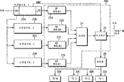
Fig. 2 is the block schematic diagram of explanation according to the domestic network system structure of the preferred embodiments of the present invention; And
Fig. 3 is the block schematic diagram of explanation set-top box mainboard structure shown in Figure 2.
Preferred embodiment describes in detail
The preferred embodiments of the present invention are described in detail in detail below.In the accompanying drawings, identical or similar parts are represented with identical label, although they appear in the different accompanying drawings.For clarity sake, ignore the relevant well-known functions and the detailed description of configuration here, because they may make theme of the present invention indeterminate.
Fig. 2 is the principle calcspar of explanation according to the domestic network system structure of the preferred embodiments of the present invention.
With reference to Fig. 2, set-top box comprise a set-top box mainboard 20A and a plurality of handset top box plate 20B ... 20N.Each set-top box plate can be installed to set-top box easily or unload from set-top box, as the characteristic of personal computer (PC) module card.Be installed in set-top box mainboard 20A and set-top box daughter board 20B on the set-top box ..., the sum of 20N is equivalent to display unit 30A, 30B ..., the sum of 30N.For example,, be installed in set-top box mainboard 20A and set-top box daughter board 20B on the set-top box so in domestic network system if the number of the display unit that is comprised is 5 ..., the sum of 20N is 5.
Set-top box mainboard 20A is via transmission medium, as optical fiber, coaxial cable, spiral twisted-pair feeder (telephone wire), satellite transmits etc., link to each other with network, simultaneously a plurality of set-top box daughter board 20B, ..., each of 20N is connected to the network interface unit (NIU) of set-top box mainboard 20A.
Fig. 3 is the principle calcspar of the internal structure of explanation set-top box mainboard 20A shown in Figure 2.
With reference to Fig. 3, set-top box mainboard 20A comprises a microprocessor 32, memory 34,36, Motion Picture Experts Groups of network interface unit (NIU) (MPEG) decoder 38, Voice ﹠ Video output 40, I/O part (I/O) 42 and user interface part 44.The integrated operation of microprocessor 32 controller top box mainboard 20A.Memory 34 comprises read-only memory (ROM) and random-access memory (ram).The various control programs of microprocessor 32 are mapped among the ROM, and various other control signals and data are kept among the RAM or from RAM under microprocessor 32 controls and read.NIU 36 as telephone wire or optical cable, is connected to network via transmission medium, and its modulation and demodulation is transmitted and received signal between network and mpeg decoder 38, and exports modulated or demodulated signal therefrom.
More particularly, NIU 36 is made up of a transmitter and a receiver.The mpeg data stream that receiver adopts the demodulation of carrierless amplitude phase modulated (CAP)-16 method to import from network via transmission medium, and export that the demodulation mpeg data flows to mpeg decoder 38.Otherwise transmitter adopts Quadrature Phase Shift Keying (QPSK) method modulating data during upstream operation, and arrives network via transmission medium output modulated data.
The mpeg data stream that mpeg decoder 38 is received from NIU 36 by microprocessor 32 controls and decoding, the mpeg data stream of will decoding then is sent to Voice ﹠ Video output 40 as a voice data and a video data.The video output of Voice ﹠ Video output 40 will be transformed into corresponding analog video signal through the digital video signal that mpeg decoder 38 is handled, and the conversion analog video signal outputs to an external display unit via I/O part 42 (i.e. an audio/video (A/V) socket).On the other hand, the audio output part branch of Voice ﹠ Video output 40 will be transformed into corresponding simulated audio signal through the digital audio and video signals that mpeg decoder 38 is handled, and amplify institute's conversion simulated audio signal that will add to the external display unit via I/O part 42 (i.e. an audio/video (A/V) socket).User interface part 44 is circuit that are used for user interactions, and it comprises a remote controller with the key input.
Set-top box daughter board 20B, 20C ..., 20N is configured to have identical configuration with set-top box mainboard 20A, but does not comprise as shown in Figure 3 NIU 36 and user interface 44.Therefore, the discussion of like is omitted, what make an exception is at set-top box daughter board 20B, 20C, ..., the microprocessor 32 that is comprised in each of 20N is kept in touch mutually with the microprocessor 32 of set-top box mainboard 20A, and carries out proper operation separately under microprocessor 32 controls of set-top box mainboard 20A.In addition, with reference to Fig. 2, set-top box mainboard 20A and set-top box daughter board 20B, 20C ..., 20N is connected to radio frequency modulator 22A separately as follows, 22B ..., 22N, that is, make each set-top box mainboard and daughter board 20A, 20B, 20C ..., 20N is corresponding to relevant radio frequency modulator 22A, 22B ..., among the 22N one.For the sake of simplicity, below from set-top box mainboard 20A and set-top box daughter board 20B, 20C ..., each signal of 20N output is called " business tine signal ".
The square of representing with label 100 among Fig. 2 is preferably in the single component 100 and realizes, it comprises a plurality of radio frequency modulator 22A, 22B ..., 22N, frequency mixer 24 and switch sections 26.The realization of square 100 has increased economic and practical.
Now, the explanation according to the operation of this embodiment of the present invention provides hereinafter in more detail with reference to Fig. 2 and 3.
NIU 36 on set-top box mainboard 20A is via transmission medium, as optical fiber, coaxial cable, spiral twisted-pair cable (telephone wire) and satellite transmits, during from network reception business tine data (digital TV broadcast signal, internet data, VOD data etc.), the business tine data that NIU 36 demodulation are received.Then, NIU 36 supplies with set-top box mainboard 20A and set-top box daughter board 20B with demodulated business tine data, 20C ..., the MPEG demodulator 38 of 20N.
Set-top box mainboard 20A relevant and set-top box daughter board 20B with Fig. 3,20C ..., the composed component of 20N is performed to produce the business tine signal.After this, set-top box mainboard 20A and set-top box daughter board 20B, 20C ..., 20N adds to radio frequency modulator 22A respectively with the business tine signal, 22B ..., 22N.At this moment, the business tine signal is the form of analog signal and can be classified as vision signal, audio signal and text signal.Each radio frequency modulator 22A, 22B ..., 22N is distributing to each television set 30A, 30B ..., modulation slave top box mainboard 20A and set-top box daughter board 20B on the different channels frequency range of each channel of 30N, 20C ..., the business tine signal of 20N output.Then, the modulated business tine signal on each frequency channels is added to frequency mixer 24.For example, the modulated that the channel A of radio frequency modulator 22A can be set respectively is 55.25MHz, the modulated of the channel B of radio frequency modulator 22B is 67.25MHz, the modulated of the channel C of radio frequency modulator 22C is 73.25MHz, ..., the modulated of the channel N of radio frequency modulator 22N is 135.25MHz.To the NTSC broadcast system, when considering that modulated from radio frequency modulator is output to 3 channels (vision carrier frequency: 61.25MHz) or 4 channels (vision carrier frequency: in the time of 67.25MHz), can adopt each channel frequency by TSC-system formula regulation.
Frequency mixer will be from radio frequency modulator 22A, 22B ..., each modulated business tine signal of 22N output mixes and adds to switch sections 26.At this moment, will be from the frequency range of frequency mixer 24 outputs as mentioned above in 54MHz to 140MHz scope.
In addition, the normal tv broadcast singal that receives by antenna is added to switch sections 26.Switch sections 26 is selected via the television broadcasting signal of antenna reception or from a signal in the output signal of frequency mixer 24 according to the switch controlling signal SWC that is supplied with by the microprocessor on the set-top box mainboard 20A 32.Switch controlling signal is watched selection based on one that is made by the user.Then, distributor 28 will correspondingly be assigned to a plurality of television set 30A from the output of switch sections 26,30B ..., 30N.
Therefore, watch television set 30A, 30B ..., the user of a television set among the 30N can watch different business tine (or VOD program) according to the channel of being selected by the user.For example, when the user of television set 30A uses the selected selectively desirable business tine of remote controller of set-top box to television set 30A, and when using the remote controller selective channel A of television set 30A, then the user can be provided by the business tine that provides via radio frequency modulator 22A.If user's selective channel B, then the user can be provided by the business tine that provides via radio frequency modulator 22B.
As mentioned above, the advantage of domestic network system of the present invention is, though a plurality of users in room separately utilize a subscriber equipment, promptly are connected to the satellite broadcast receiver of network via a transmission medium, they can watch the corresponding business content via a plurality of display units.In addition, each in a plurality of users in the room separately can be selected desirable channel of selection from N channel by channel simply, to watch the corresponding business content.
Although the present invention one is described with reference to the most practical and preferred embodiment of considering at present,, should be understood that the present invention is not limited to described embodiment for example as the VOD business of two-way multimedia service example.Otherwise, under the spirit and scope situation of claims, can make various distortion.
Claims (9)
1. a set-top box that links to each other with network is used for being controlled at the multimedia messages that a plurality of display units offer the beholder, and this set-top box comprises:
The set-top box plate that a plurality of and described set-top box links to each other is used for and will becomes the corresponding business content signal via the signal transformation that transmission medium received;
A plurality of radio frequency modulators that link to each other with described a plurality of set-top box plates respectively are used for the described business tine signal through conversion of modulation on the different channels frequency range, and described different channels frequency is corresponding to each described a plurality of described display units; With
With the mixer device that each described radio frequency modulator links to each other, be used to mix the described modulated signal that comes from described a plurality of described radio frequency modulators, to add to described a plurality of described display unit.
2. according to the set-top box of claim 1, also comprise:
With the switching device that described mixer device links to each other, be used to respond the request that the user makes, select the output signal of coming from described mixer device or via broadcast singal that antenna received; With
With the distributor that described switching device links to each other, be used to distribute the output signal of coming from described switching device to described a plurality of described display units.
3. according to the set-top box of claim 2, wherein said radio frequency modulator, described mixer device and described switching device are comprised in the single module.
4. according to the set-top box of claim 1 or 2, wherein said a plurality of described set-top box plates comprise:
A set-top box mainboard that links to each other with described network via described transmission medium; With
Its each a plurality of set-top box daughter boards that link to each other with described set-top box mainboard, wherein,
The sum of described set-top box mainboard and set-top box daughter board equals the number of set-top box plate.
5. according to the set-top box of claim 4, wherein said set-top box mainboard comprises:
With the network interface unit that described transmission medium links to each other, be used for and described network interface, described network interface unit links to each other with described set-top box daughter board;
First mpeg decoder, the signal decoding that is used for sending to described network interface unit from described transmission medium becomes the corresponding digital output signal;
The first Voice ﹠ Video output, the described digital output signal that is used for coming from described mpeg decoder is transformed into corresponding Voice ﹠ Video signal;
With described network interface unit and the first microprocessor that described mpeg decoder links to each other, be used to control the integrated operation of described set-top box mainboard;
The first memory device that links to each other with described microprocessor; With
With the user interface that described microprocessor links to each other, be used for and user interface.
6. according to the set-top box of claim 5, wherein said set-top box mainboard and described user interface are used for controlling selectively the output signal of described switching device.
7. according to the set-top box of claim 5, wherein said network interface unit also comprises Receiver And Transmitter, the described signal that described receiver adopts the demodulation of carrierless amplitude phase modulated method to come from described network, described transmitter adopts Quadrature Phase Shift Keying method modulation upward signal, and outputs to described network via described transmission medium.
8. according to the set-top box of claim 5, wherein said set-top box daughter board comprises:
Second mpeg decoder that links to each other with the described network interface unit of described set-top box mainboard, the output signal that is used for coming from described network interface unit is decoded into the corresponding digital output signal;
One second Voice ﹠ Video output, the described digital output signal that is used for coming from described second mpeg decoder is transformed into corresponding Voice ﹠ Video signal;
Second microprocessor that links to each other with the described first microprocessor of described set-top box mainboard is used to control the integrated operation of described set-top box daughter board; With
A second memory device that links to each other with described second microprocessor.
9. according to the set-top box of claim 1 or 2, wherein said transmission medium comprises optical fiber, coaxial cable, twisted-pair feeder or satellite.
Applications Claiming Priority (2)
| Application Number | Priority Date | Filing Date | Title |
|---|---|---|---|
| KR1999/28086 | 1999-07-12 | ||
| KR1019990028086A KR100322050B1 (en) | 1999-07-12 | 1999-07-12 | Home network system for bidirectional multimedia service |
Publications (2)
| Publication Number | Publication Date |
|---|---|
| CN1317188A CN1317188A (en) | 2001-10-10 |
| CN1136698C true CN1136698C (en) | 2004-01-28 |
Family
ID=19601162
Family Applications (1)
| Application Number | Title | Priority Date | Filing Date |
|---|---|---|---|
| CNB008013705A Expired - Fee Related CN1136698C (en) | 1999-07-12 | 2000-07-12 | Home network system for two-way multimedia service |
Country Status (8)
| Country | Link |
|---|---|
| EP (1) | EP1112640A4 (en) |
| JP (1) | JP2003504960A (en) |
| KR (1) | KR100322050B1 (en) |
| CN (1) | CN1136698C (en) |
| AU (1) | AU760444B2 (en) |
| CA (1) | CA2343065A1 (en) |
| RU (1) | RU2222870C2 (en) |
| WO (1) | WO2001005097A1 (en) |
Families Citing this family (20)
| Publication number | Priority date | Publication date | Assignee | Title |
|---|---|---|---|---|
| KR100755830B1 (en) * | 2001-02-08 | 2007-09-07 | 엘지전자 주식회사 | set-top box system for multi display application |
| WO2002065771A1 (en) * | 2001-02-09 | 2002-08-22 | Quadriga Technology Limited | System for and method of distributing television, video and other signals |
| US20090031419A1 (en) | 2001-05-24 | 2009-01-29 | Indra Laksono | Multimedia system and server and methods for use therewith |
| US8291457B2 (en) | 2001-05-24 | 2012-10-16 | Vixs Systems, Inc. | Channel selection in a multimedia system |
| WO2003005719A2 (en) * | 2001-05-24 | 2003-01-16 | Vixs Systems Inc. | Method and apparatus for managing resources and multiplexing a plurality of channels in a multimedia system |
| US7617515B1 (en) | 2001-05-24 | 2009-11-10 | Vixs Systems, Inc. | Method and apparatus for managing resources in a multimedia system |
| KR100447584B1 (en) * | 2002-01-24 | 2004-09-07 | 코스텔(주) | A multi-function Audio/Video system having a Audio/Video apparatus and a Mobile computer |
| KR100464262B1 (en) * | 2002-02-26 | 2005-01-03 | 코스텔(주) | Multi-function Audio/Video system having a multi-function Audio/Video apparatus and a Mobile computer |
| KR20040044208A (en) * | 2002-11-19 | 2004-05-28 | 엘지전자 주식회사 | digital data broadcasting display method of digital television system |
| CN100579089C (en) * | 2003-09-26 | 2010-01-06 | 无极公司 | Device control system, method, and apparatus |
| CN1662007B (en) * | 2004-02-28 | 2011-03-30 | 深圳市朗科科技股份有限公司 | System for controlling household digital equipment based on wireless |
| CN1662006B (en) * | 2004-02-28 | 2011-03-30 | 深圳市朗科科技股份有限公司 | System of controlling household digital equipment based on wireless |
| KR100772392B1 (en) | 2006-02-07 | 2007-11-01 | 삼성전자주식회사 | Method and apparatus for processing contents using TV channel in home network |
| KR101112737B1 (en) | 2007-02-06 | 2012-03-14 | 삼성전자주식회사 | Apparatus and Method for converting multimedia contents, and Distribution system of multimedia contents |
| CN101034966B (en) * | 2007-04-06 | 2010-05-26 | 华为技术有限公司 | STB and master-slave STB system |
| KR101668852B1 (en) * | 2009-01-30 | 2016-10-24 | 톰슨 라이센싱 | System and method for combined home network communications and broadcast reception in a settop box |
| US9185509B2 (en) * | 2009-12-23 | 2015-11-10 | Nokia Technologies Oy | Apparatus for processing of audio signals |
| TWI498001B (en) * | 2013-07-05 | 2015-08-21 | Aten Int Co Ltd | Distributed video control system and distributed video control method |
| CN103957446B (en) * | 2014-05-16 | 2017-07-18 | 珠海迈科智能科技股份有限公司 | Set top box and its control method that support multi-user based on linux uses |
| KR20160131512A (en) | 2015-05-07 | 2016-11-16 | 주식회사 세움이앤씨 건축사사무소 | Ventilation system for elevator hall |
Family Cites Families (13)
| Publication number | Priority date | Publication date | Assignee | Title |
|---|---|---|---|---|
| GB2214758A (en) * | 1988-01-22 | 1989-09-06 | Philips Electronic Associated | Signal distribution network system |
| GB8927063D0 (en) * | 1989-11-30 | 1990-01-31 | Thorn Emi Business Communicati | Video network |
| US5389963A (en) * | 1992-02-05 | 1995-02-14 | Dynacom, Inc. | System for selectively interconnecting audio-video sources and receivers |
| AU693148B2 (en) * | 1993-12-02 | 1998-06-25 | Sedna Patent Services, Llc | Network manager for cable television system headends |
| US5522042A (en) * | 1994-01-28 | 1996-05-28 | Cabletron Systems, Inc. | Distributed chassis agent for distributed network management |
| DE19511332A1 (en) * | 1995-03-28 | 1996-10-02 | Sel Alcatel Ag | Broadband distribution system and method therefor |
| US5708961A (en) * | 1995-05-01 | 1998-01-13 | Bell Atlantic Network Services, Inc. | Wireless on-premises video distribution using digital multiplexing |
| US5721829A (en) * | 1995-05-05 | 1998-02-24 | Microsoft Corporation | System for automatic pause/resume of content delivered on a channel in response to switching to and from that channel and resuming so that a portion of the content is repeated |
| US5682597A (en) * | 1995-06-15 | 1997-10-28 | International Business Machines Corporation | Hybrid video-on-demand based on a near-video-on-demand system |
| KR0184043B1 (en) * | 1995-08-01 | 1999-05-01 | 구자홍 | Multi-interface system for a vod |
| AU732339B2 (en) * | 1997-02-19 | 2001-04-12 | Next Level Communications Inc. | Video, data and telephony gateway |
| JP3871412B2 (en) * | 1997-10-03 | 2007-01-24 | 株式会社ネオレックス | WWW joint viewing system |
| CA2313074A1 (en) * | 1997-12-24 | 1999-07-08 | Adc Telecommunications, Inc. | Test access system and method for digital communication networks |
-
1999
- 1999-07-12 KR KR1019990028086A patent/KR100322050B1/en not_active IP Right Cessation
-
2000
- 2000-07-12 EP EP00942508A patent/EP1112640A4/en not_active Withdrawn
- 2000-07-12 CA CA002343065A patent/CA2343065A1/en not_active Abandoned
- 2000-07-12 JP JP2001510191A patent/JP2003504960A/en active Pending
- 2000-07-12 CN CNB008013705A patent/CN1136698C/en not_active Expired - Fee Related
- 2000-07-12 AU AU57120/00A patent/AU760444B2/en not_active Ceased
- 2000-07-12 RU RU2001106660/09A patent/RU2222870C2/en not_active IP Right Cessation
- 2000-07-12 WO PCT/KR2000/000751 patent/WO2001005097A1/en active IP Right Grant
Also Published As
| Publication number | Publication date |
|---|---|
| AU760444B2 (en) | 2003-05-15 |
| RU2222870C2 (en) | 2004-01-27 |
| AU5712000A (en) | 2001-01-30 |
| KR100322050B1 (en) | 2002-02-06 |
| JP2003504960A (en) | 2003-02-04 |
| KR20010009630A (en) | 2001-02-05 |
| WO2001005097A1 (en) | 2001-01-18 |
| EP1112640A4 (en) | 2006-08-30 |
| CN1317188A (en) | 2001-10-10 |
| EP1112640A1 (en) | 2001-07-04 |
| CA2343065A1 (en) | 2001-01-18 |
Similar Documents
| Publication | Publication Date | Title |
|---|---|---|
| CN1136698C (en) | Home network system for two-way multimedia service | |
| US5613190A (en) | Customer premise wireless distribution of audio-video, control signals and voice | |
| US5610916A (en) | Shared receiving systems utilizing telephone cables as video drops | |
| CN100388777C (en) | Cable television system and method for compatible bandwidth upgrade using embedded digital channels | |
| EP1670247A2 (en) | Distribution and networking of television, video and other signals | |
| US6211901B1 (en) | Video data distributing device by video on demand | |
| US20030120742A1 (en) | Home network system | |
| CN1108699C (en) | Transmission and reception of TV. programs and additional data service | |
| WO1994013107B1 (en) | Advanced set top terminal for cable television delivery systems | |
| KR19990021917A (en) | Asymmetric Data Communication System | |
| CN100375528C (en) | Video/audio/data distribution architecture | |
| CN102577416A (en) | Method, device and system for selectively outputting multimedia contents | |
| EP0652677A2 (en) | Terrestrial television broadcast system converter | |
| US20050289638A1 (en) | Methods, systems, and products for providing broadcast video and IP data over a common, shared interface | |
| US20040155985A1 (en) | Interface unit | |
| US8418212B2 (en) | Method and system of providing digital video remodulation | |
| CN100442843C (en) | System and method for realizing multi-media service in wide-band video system | |
| KR20020001039A (en) | Service Method And Apparatus For Internet Satellite Broadcast Using Internet And Satellite Network | |
| KR100689045B1 (en) | Cable modem set-top-box apparatus capable of multi-room broadcasting, and method thereof | |
| KR19990015770A (en) | Game service device using digital cable TV system |
Legal Events
| Date | Code | Title | Description |
|---|---|---|---|
| C06 | Publication | ||
| PB01 | Publication | ||
| C10 | Entry into substantive examination | ||
| SE01 | Entry into force of request for substantive examination | ||
| C14 | Grant of patent or utility model | ||
| GR01 | Patent grant | ||
| C17 | Cessation of patent right | ||
| CF01 | Termination of patent right due to non-payment of annual fee |
Granted publication date: 20040128 |