CN113623700A - Oil smoke filter screen washs cleaning machine tool - Google Patents
Oil smoke filter screen washs cleaning machine tool Download PDFInfo
- Publication number
- CN113623700A CN113623700A CN202111184910.6A CN202111184910A CN113623700A CN 113623700 A CN113623700 A CN 113623700A CN 202111184910 A CN202111184910 A CN 202111184910A CN 113623700 A CN113623700 A CN 113623700A
- Authority
- CN
- China
- Prior art keywords
- filter screen
- water tank
- rotating shaft
- horizontal
- square frame
- Prior art date
- Legal status (The legal status is an assumption and is not a legal conclusion. Google has not performed a legal analysis and makes no representation as to the accuracy of the status listed.)
- Pending
Links
Images


Classifications
-
- F—MECHANICAL ENGINEERING; LIGHTING; HEATING; WEAPONS; BLASTING
- F24—HEATING; RANGES; VENTILATING
- F24C—DOMESTIC STOVES OR RANGES ; DETAILS OF DOMESTIC STOVES OR RANGES, OF GENERAL APPLICATION
- F24C15/00—Details
- F24C15/20—Removing cooking fumes
- F24C15/2035—Arrangement or mounting of filters
-
- F—MECHANICAL ENGINEERING; LIGHTING; HEATING; WEAPONS; BLASTING
- F24—HEATING; RANGES; VENTILATING
- F24C—DOMESTIC STOVES OR RANGES ; DETAILS OF DOMESTIC STOVES OR RANGES, OF GENERAL APPLICATION
- F24C15/00—Details
- F24C15/20—Removing cooking fumes
- F24C15/2057—Removing cooking fumes using a cleaning liquid
Abstract
The invention belongs to the technical field of oil fume treatment, and particularly relates to an oil fume filter screen cleaning and cleaning machine which comprises a square water tank, wherein lifting plates are arranged on the front inner wall and the rear inner wall of the water tank respectively, the lifting plates are vertically matched with the inner wall of the water tank in a sliding manner, a hydraulic cylinder is arranged on the inner wall of the water tank, and the end part of a telescopic section of the hydraulic cylinder is fixedly connected to the lifting plates; a square frame is arranged between the two lifting plates; a fixing mechanism is arranged on the square frame; contraband-shaped frames are slidably mounted on the left side plate and the right side plate of the water tank; a rotating shaft is rotatably arranged between the two Contraband-shaped frames, and a brush roller and a driven gear are arranged on the rotating shaft; the bracket is provided with a driving motor, and an output shaft of the driving motor is provided with a driving gear; the invention ensures that the filter screen can be uniformly scrubbed, avoids the situation that oil stains remain in gaps of the filter screen, and improves the scrubbing effect on the filter screen; the invention makes the oil stain and the filter screen fully separated by the water flow.
Description
Technical Field
The invention belongs to the technical field of oil fume treatment, and particularly relates to a cleaning treatment machine for an oil fume filter screen.
Background
Filter screen on the lampblack absorber is mainly the effect of playing the filtered oil cigarette, when the oil smoke passes through the filter screen, the grease can be attached to on the filter screen, play certain guard action to the lampblack absorber, when the grease on the filter screen accumulates to the certain extent, should in time wash the filter screen, spray the cleaner on the filter screen earlier usually, then the manual work is earlier scrubbed the filter screen with the brush, wash the filter screen with clear water at last, this kind of mode has following problem when the actual operation: (1) when the brush is manually brushed, the brush is difficult to ensure that all parts of the filter screen are uniformly and fully cleaned, and oil stains are easy to remain in the gaps of the filter screen; (2) when the filter screen is cleaned, the oil stain dissolved on the filter screen is difficult to be ensured to be fully separated from the filter screen, and the cleaning effect is influenced.
Disclosure of Invention
In order to solve the technical problems, the invention adopts the following technical scheme: a cleaning treatment machine for an oil smoke filter screen comprises a square water tank, clear water is filled in the water tank, horizontal lifting plates are arranged on the front inner wall and the rear inner wall of the water tank, the lifting plates are vertically and slidably matched with the inner wall of the water tank, a hydraulic cylinder is vertically and fixedly arranged on the part, above the lifting plates, of the inner wall of the water tank, and the end part of a telescopic section of the hydraulic cylinder is fixedly connected to the lifting plates; a horizontal square frame is arranged between the two lifting plates.
The square frame is provided with a fixing mechanism, the fixing mechanism comprises two sliding frames symmetrically arranged on the top surface of the square frame, the sliding frames are in sliding fit with the square frame, and the sliding frames penetrate through the square frame; a horizontal bidirectional screw rod is rotatably arranged on the bottom surface of the square frame through a screw rod bracket, and the bidirectional screw rod penetrates through the two sliding frames in a thread fit mode; the end part of the bidirectional screw rod is fixedly provided with a knob.
Horizontally placing the filter screen on the square frame, driving the bidirectional screw to rotate through the rotating knob, driving the two sliding frames to move oppositely through the bidirectional screw until the sliding frames are attached to the frame of the filter screen, and clamping and fixing the filter screen through the sliding frames; the cleaning agent is manually sprayed onto the filter screen.
The top parts of the left side plate and the right side plate of the water tank are both provided with horizontal grooves, and Contraband-shaped frames with downward openings are horizontally installed in a sliding mode through the horizontal grooves; a horizontal rotating shaft is rotatably arranged between the vertical sections of the two Contraband-shaped frames, a brush roller which is overlapped with the axis of the rotating shaft is arranged on the rotating shaft, and a driven gear which is overlapped with the axis of the rotating shaft is fixedly arranged on the rotating shaft; one Contraband-shaped frame is horizontally and fixedly provided with a driving motor through a motor base, and an output shaft of the driving motor is fixedly provided with a driving gear which is meshed with the driven gear.
The driving gear is driven to rotate by the driving motor, the driving gear drives the driven gear to rotate, and the driven gear drives the rotating shaft and the brush roller to synchronously rotate; the two lifting brackets are pushed to move along the horizontal groove, so that the brush roller cleans the filter screen in the horizontal direction; after cleaning, drive the reciprocal lift of lifter plate through the pneumatic cylinder, square frame, fixed establishment and filter screen are reciprocal in step and are gone up and down, produce relative movement from top to bottom between the clear water in filter screen and the basin to make the oil stain and the filter screen separation of dissolving on the filter screen through the rivers effect.
As a preferred technical scheme of the invention, a plurality of rubber strips are uniformly and fixedly arranged at the positions, above the square frame, of the opposite surfaces of the two sliding frames so as to increase the friction force between the sliding frames and the frame of the filter screen and avoid the situation that the filter screen falls off from the space between the two sliding frames.
As a preferred technical scheme, two bearing blocks are fixedly arranged on the top surface of the sliding frame, a limiting plate is rotatably arranged between the two bearing blocks, a convex block penetrating through the bearing blocks is arranged on the side surface of the limiting plate, a square groove is formed in the side surface of the convex block, and a positioning block matched with the square groove is slidably arranged on the top surface of the sliding frame; after the sliding frame tightly clamps the filter screen frame, the limiting plate is rotated to enable the limiting plate to reach the horizontal state, the limiting plate is positioned through the positioning block, the limiting plate is enabled to keep the horizontal state, the limiting plate is enabled to limit the filter screen in the vertical direction, and the situation that the filter screen drops from the two sliding frames is further avoided.
As a preferred technical scheme of the invention, the square frame is connected with the two lifting plates through a horizontal elastic telescopic rod; a guide plate with a wave-shaped surface is vertically and fixedly arranged on the inner wall of the rear side of the water tank, and a horizontal guide rod is fixedly arranged on the rear end face of the square frame; the end of the guide rod is matched with the wavy surface of the guide plate.
As a preferable technical scheme of the invention, the end part of the guide rod is rotatably provided with a roller, and the roller is in rolling fit with the wavy surface of the guide plate so as to reduce the friction force between the guide rod and the guide plate.
As a preferable technical scheme of the invention, the two Contraband-shaped frames are fixedly connected through the connecting frame, and the two 21274can be ensured to move synchronously by pushing the connecting frame.
As a preferred technical scheme of the invention, the rotating shaft is fixedly provided with guide strips parallel to the rotating shaft, and the brush roller is in sliding fit with the rotating shaft through the guide strips; a return spring is fixedly connected between one end of the brush roller and the driven gear; two symmetrical horizontal rods are fixedly installed at the other end of the brush roller, and a first magnet block is fixedly installed at the end part of each horizontal rod; the surface of the vertical section of the Contraband-shaped frame is fixedly provided with a second magnet block which has the same magnetism as the first magnet block.
According to a preferable technical scheme of the invention, the inner circumferential surface of the brush roller is provided with a plurality of balls, and the balls are in rolling fit with the rotating shaft so as to reduce the friction force between the brush roller and the rotating shaft and ensure that the brush roller smoothly reciprocates along the axial direction of the rotating shaft.
The invention has at least the following beneficial effects: (1) according to the invention, the filter screen is fixed on the square frame in a horizontal state through the fixing mechanism, and the Contraband-shaped frame drives the rotating brush roller to scrub the filter screen along the horizontal direction, so that the filter screen can be uniformly scrubbed; in the brushing process, the brush roller moves in a reciprocating manner along the axial direction of the brush roller while moving horizontally, so that the filter screen is brushed in different directions, the brushing effect on the filter screen is improved, and the situation that oil stains are remained in gaps of the filter screen is avoided.
(2) According to the invention, the square frame, the fixing mechanism and the filter screen are driven by the hydraulic cylinder to reciprocate up and down, so that the filter screen is fully contacted with water in the water tank, and oil stains dissolved on the filter screen are fully separated from the filter screen through water flow; when the square frame, the fixing mechanism and the filter screen move up and down in a reciprocating manner, the square frame, the fixing mechanism and the filter screen synchronously move in a reciprocating manner along the horizontal direction under the interaction of the guide plate and the guide rod, so that the friction effect between the filter screen and water is further enhanced, and the effect of separating oil stains from the filter screen is improved.
Drawings
The invention is further illustrated with reference to the following figures and examples.
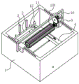
Fig. 1 is a schematic perspective view of a first perspective structure of a machine for cleaning and treating a soot filter in an embodiment of the present invention.
Fig. 2 is a schematic second perspective view of the lampblack filter cleaning machine in the embodiment of the invention.
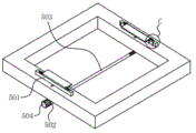
Fig. 3 is a schematic perspective view of a square frame and a fixing mechanism according to an embodiment of the present invention.
Fig. 4 is an enlarged schematic view of a portion a of fig. 1.
Fig. 5 is an enlarged schematic view of fig. 2 at B.
Fig. 6 is an enlarged schematic view at C in fig. 3.
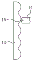
Fig. 7 is a schematic structural view of a guide plate, a guide rod and a roller in the embodiment of the invention.
FIG. 8 is a schematic view showing a part of the internal structure of the brush roller and the rotating shaft according to the embodiment of the present invention.
In the figure: 1. a water tank; 101. a horizontal groove; 2. a lifting plate; 3. a hydraulic cylinder; 4. a square frame; 5. a fixing mechanism; 501. a carriage; 502. a lead screw bracket; 503. a bidirectional lead screw; 504. a knob; 505. a rubber strip; 506. a bearing block; 507. a limiting plate; 508. positioning blocks; 6. contraband form rack; 7. a rotating shaft; 8. a brush roller; 9. a driven gear; 10. a drive motor; 11. a drive gear; 12. an elastic telescopic rod; 13. a guide plate; 14. a guide bar; 15. a roller; 16. a connecting frame; 17. a guide strip; 18. a return spring; 19. a horizontal bar; 20. a first magnet block; 21. a second magnet block; 22. and a ball.
Detailed Description
The embodiments of the invention will be described in detail below with reference to the drawings, but the invention can be implemented in many different ways as defined and covered by the claims.
As shown in fig. 1, the present embodiment provides a lampblack filter screen cleaning and processing machine, which includes a square water tank 1, clear water is filled in the water tank 1, a water outlet is formed in a side wall of the water tank 1, horizontal lifting plates 2 are respectively installed on a front inner wall and a rear inner wall of the water tank 1, the lifting plates 2 are vertically and slidably matched with the inner wall of the water tank 1, a hydraulic cylinder 3 is vertically and fixedly installed on a part of the inner wall of the water tank 1, which is located above the lifting plates 2, and an end part of a telescopic section of the hydraulic cylinder 3 is fixedly connected to the lifting plates 2; a horizontal square frame 4 is arranged between the two lifting plates 2 through a horizontal elastic telescopic rod 12.
As shown in fig. 2, 3 and 6, the fixing mechanism 5 is mounted on the square frame 4, the fixing mechanism 5 includes two sliding frames 501 symmetrically mounted on the top surface of the square frame 4, the sliding frames 501 are slidably engaged with the square frame 4, and the sliding frames 501 penetrate through the square frame 4; a horizontal bidirectional screw 503 is rotatably mounted on the bottom surface of the square frame 4 through a screw bracket 502, and the bidirectional screw 503 penetrates through the two sliding frames 501 in a threaded fit manner; a knob 504 is fixedly arranged at the end part of the bidirectional screw 503; a plurality of rubber strips 505 are uniformly and fixedly arranged on the opposite surfaces of the two sliding frames 501 above the square frame 4; sliding frame 501 top surface fixed mounting has two bearing piece 506, rotates between two bearing piece 506 and installs limiting plate 507, and limiting plate 507 side is provided with the lug that runs through bearing piece 506, and square groove has been seted up to the lug side, and sliding frame 501 top surface slidable mounting has the locating piece 508 of mutually supporting with square groove.
As shown in fig. 1, 2, 4 and 5, horizontal grooves 101 are formed in the top of the left side plate and the top of the right side plate of the water tank 1, and Contraband-shaped frames 6 with downward openings are horizontally and slidably mounted through the horizontal grooves 101; a horizontal rotating shaft 7 is rotatably arranged between the vertical sections of the two Contraband-shaped frames 6, a brush roller 8 which is superposed with the axis of the rotating shaft 7 is arranged on the rotating shaft 7, and a driven gear 9 which is superposed with the axis of the rotating shaft 7 is fixedly arranged on the rotating shaft 7; the two Contraband-shaped frames 6 are fixedly connected through the connecting frame 16, and the two Contraband-shaped frames 6 are ensured to move synchronously by pushing the connecting frame 16; one Contraband-shaped frame 6 is horizontally and fixedly provided with a driving motor 10 through a motor base, and an output shaft of the driving motor 10 is fixedly provided with a driving gear 11 which is meshed with the driven gear 9.
As shown in fig. 1 and 7, a guide plate 13 with a wave-shaped surface is vertically and fixedly installed on the inner wall of the rear side of the water tank 1, and a horizontal guide rod 14 is fixedly installed on the rear end surface of the square frame 4; the end part of the guide rod 14 is matched with the wavy surface of the guide plate 13; the end part of the guide rod 14 is rotatably provided with a roller 15, and the roller 15 is in rolling fit with the wavy surface of the guide plate 13 so as to reduce the friction force between the guide rod 14 and the guide plate 13; the lifter plate 2 drives the square frame 4, the guide rod 14 and the filter screen through the elastic telescopic rod 12 to synchronously move up and down, and the guide rod 14 and the square frame 4 horizontally reciprocate under the thrust action of the guide plate 13 and the elastic action of the elastic telescopic rod 12, so that the filter screen horizontally reciprocates while reciprocating up and down, and the effect of separating oil stains on the filter screen from the filter screen by water flow is further improved.
As shown in fig. 4, 5 and 8, the rotating shaft 7 is fixedly provided with guide strips 17 parallel to the rotating shaft, and the brush roller 8 is in sliding fit with the rotating shaft 7 through the guide strips 17; a return spring 18 is fixedly connected between one end of the brush roller 8 and the driven gear 9; two symmetrical horizontal rods 19 are fixedly arranged at the other end of the brush roller 8, and a first magnet block 20 is fixedly arranged at the end part of each horizontal rod 19; contraband the vertical section surface of the frame 6 is fixed with the second magnet block 21 with the same magnetism as the first magnet block 20; the inner circumferential surface of the brush roller 8 is provided with a plurality of balls 22, and the balls 22 are in rolling fit with the rotating shaft 7 so as to reduce the friction force between the brush roller 8 and the rotating shaft 7 and ensure that the brush roller 8 can smoothly reciprocate along the axial direction of the rotating shaft 7; when the rotating shaft 7 drives the brush roller 8 to rotate, the horizontal rod 19 and the first magnet block 20 move synchronously, when the first magnet block 20 rotates to a position corresponding to the second magnet block 21, mutual repulsion force is generated between the first magnet block and the second magnet block, and the horizontal rod 19, the first magnet block 20 and the brush roller 8 move axially along the rotating shaft 7 and compress the return spring 18; when the first magnet block 20 leaves the position corresponding to the second magnet block 21, the mutual repulsion force between the first magnet block and the second magnet block disappears, and the resilience force of the return spring 18 acts on the horizontal rod 19, the first magnet block 20 and the brush roller 8 to move along the axial direction of the rotating shaft 7 to reset, so that the brush roller 8 rotates and moves along the axial direction of the rotating shaft 7 to the reciprocating direction, and the cleaning effect of the brush roller 8 on the filter screen is improved.
The working process of the oil smoke filter screen cleaning and processing machine in the embodiment is as follows: horizontally placing the filter screen on the square frame 4, driving the bidirectional screw 503 to rotate by rotating the knob 504, driving the two sliding frames 501 to move oppositely by the bidirectional screw 503 until the sliding frames 501 are attached to the frame of the filter screen, and clamping and fixing the filter screen by the sliding frames 501; the limiting plate 507 is rotated to enable the limiting plate 507 to be in a horizontal state, the limiting plate 507 is positioned through the positioning block 508, the limiting plate 507 is enabled to be in the horizontal state, therefore, the filtering net is limited in the vertical direction through the limiting plate 507, and the condition that the filtering net falls off between the two sliding frames 501 is avoided; the cleaning agent is manually sprayed onto the filter screen.
The driving gear 11 is driven to rotate by the driving motor 10, the driving gear 11 drives the driven gear 9 to rotate, and the driven gear 9 drives the rotating shaft 7 and the brush roller 8 to synchronously rotate; pushing the two Contraband-shaped frames 6 to move along the horizontal groove 101, so that the brush roller 8 cleans the filter screen in the horizontal direction; in the process that the rotating shaft 7 drives the brush roller 8 to rotate, the horizontal rod 19 and the first magnet block 20 rotate synchronously, the mutually repulsive force between the first magnet block 20 and the second magnet block 21 and the resilience force of the return spring 18 enable the horizontal rod 19, the first magnet block 20 and the brush roller 8 to move axially and reciprocally along the rotating shaft 7, and the cleaning effect of the brush roller 8 on the filter screen is improved.
After cleaning, the hydraulic cylinder 3 drives the lifting plate 2 to reciprocate, the elastic telescopic rod 12, the square frame 4, the fixing mechanism 5 and the filter screen synchronously reciprocate, and the filter screen and clean water in the water tank 1 generate relative up-and-down movement, so that oil stains dissolved on the filter screen are separated from the filter screen under the action of water flow; the lifter plate 2 drives the square frame 4, the guide rod 14 and the filter screen through the elastic telescopic rod 12 to synchronously move up and down, and the guide rod 14 and the square frame 4 horizontally reciprocate under the thrust action of the guide plate 13 and the elastic action of the elastic telescopic rod 12, so that the filter screen horizontally reciprocates while reciprocating up and down, and the effect of separating oil stains on the filter screen from the filter screen by water flow is improved.
After the cleaning is finished, the fixing effect of the fixing mechanism 5 on the filter screen is released, and the filter screen is taken down from the square frame 4.
The above description is only a preferred embodiment of the present invention and is not intended to limit the present invention, and various modifications and changes may be made by those skilled in the art. Any modification, equivalent replacement, or improvement made within the spirit and principle of the present invention should be included in the protection scope of the present invention.
Claims (7)
1. The utility model provides an oil smoke filter screen washs cleaning machine tool which characterized in that: the water tank comprises a square water tank (1), a water outlet is formed in the side wall of the water tank (1), horizontal lifting plates (2) are mounted on the front inner wall and the rear inner wall of the water tank (1), the lifting plates (2) are vertically matched with the inner wall of the water tank (1) in a sliding manner, a hydraulic cylinder (3) is vertically and fixedly mounted on the part, located above the lifting plates (2), of the inner wall of the water tank (1), and the end part of a telescopic section of the hydraulic cylinder (3) is fixedly connected to the lifting plates (2); a horizontal square frame (4) is arranged between the two lifting plates (2);
a fixing mechanism (5) is arranged on the square frame (4), the fixing mechanism (5) comprises two sliding frames (501) symmetrically arranged on the top surface of the square frame (4), the sliding frames (501) are in sliding fit with the square frame (4), and the sliding frames (501) penetrate through the square frame (4); a horizontal bidirectional screw rod (503) is rotatably arranged on the bottom surface of the square frame (4) through a screw rod bracket (502), and the bidirectional screw rod (503) penetrates through the two sliding frames (501) in a threaded fit manner; a knob (504) is fixedly arranged at the end part of the bidirectional screw rod (503);
the top parts of the left side plate and the right side plate of the water tank (1) are both provided with a horizontal tank (101), and an Contraband-shaped frame (6) with a downward opening is horizontally installed in a sliding manner through the horizontal tank (101); a horizontal rotating shaft (7) is rotatably arranged between the vertical sections of the two Contraband-shaped frames (6), a brush roller (8) which is overlapped with the axis of the rotating shaft (7) is arranged on the rotating shaft (7), and a driven gear (9) which is overlapped with the axis of the rotating shaft (7) is fixedly arranged on the rotating shaft (7); one Contraband-shaped frame (6) is horizontally and fixedly provided with a driving motor (10) through a motor base, and an output shaft of the driving motor (10) is fixedly provided with a driving gear (11) which is meshed with the driven gear (9);
the rotating shaft (7) is fixedly provided with guide strips (17) which are parallel to the rotating shaft, and the brush roller (8) is in sliding fit with the rotating shaft (7) through the guide strips (17); a return spring (18) is fixedly connected between one end of the brush roller (8) and the driven gear (9); two symmetrical horizontal rods (19) are fixedly arranged at the other end of the brush roller (8), and a first magnet block (20) is fixedly arranged at the end part of each horizontal rod (19); the surface of the vertical section of the Contraband-shaped frame (6) is fixedly provided with a second magnet block (21) with the same magnetism as the first magnet block (20).
2. The machine of claim 1 for cleaning and treating a soot filter, wherein: the surfaces opposite to the two sliding frames (501) are evenly and fixedly provided with a plurality of rubber strips (505) at the positions above the square frame (4).
3. The machine of claim 1 for cleaning and treating a soot filter, wherein: sliding frame (501) top surface fixed mounting has two bearing piece (506), rotates between two bearing piece (506) and installs limiting plate (507), and limiting plate (507) side is provided with the lug that runs through bearing piece (506), and square groove has been seted up to the lug side, and sliding frame (501) top surface slidable mounting has locating piece (508) of mutually supporting with square groove.
4. The machine of claim 1 for cleaning and treating a soot filter, wherein: the square frame (4) is connected with the two lifting plates (2) through a horizontal elastic telescopic rod (12); a guide plate (13) with a wave-shaped surface is vertically and fixedly arranged on the inner wall of the rear side of the water tank (1), and a horizontal guide rod (14) is fixedly arranged on the rear end face of the square frame (4); the end of the guide rod (14) is matched with the wavy surface of the guide plate (13).
5. The lampblack filter screen cleaning and processing machine as claimed in claim 4, wherein the lampblack filter screen cleaning and processing machine comprises: the end part of the guide rod (14) is rotatably provided with a roller (15), and the roller (15) is matched with the wavy surface of the guide plate (13) in a rolling way.
6. The machine of claim 1 for cleaning and treating a soot filter, wherein: the two Contraband-shaped frames (6) are fixedly connected through a connecting frame (16).
7. The machine of claim 1 for cleaning and treating a soot filter, wherein: the inner circumferential surface of the brush roller (8) is provided with a plurality of balls (22), and the balls (22) are in rolling fit with the rotating shaft (7).
Priority Applications (1)
| Application Number | Priority Date | Filing Date | Title |
|---|---|---|---|
| CN202111184910.6A CN113623700A (en) | 2021-10-12 | 2021-10-12 | Oil smoke filter screen washs cleaning machine tool |
Applications Claiming Priority (1)
| Application Number | Priority Date | Filing Date | Title |
|---|---|---|---|
| CN202111184910.6A CN113623700A (en) | 2021-10-12 | 2021-10-12 | Oil smoke filter screen washs cleaning machine tool |
Publications (1)
| Publication Number | Publication Date |
|---|---|
| CN113623700A true CN113623700A (en) | 2021-11-09 |
Family
ID=78391048
Family Applications (1)
| Application Number | Title | Priority Date | Filing Date |
|---|---|---|---|
| CN202111184910.6A Pending CN113623700A (en) | 2021-10-12 | 2021-10-12 | Oil smoke filter screen washs cleaning machine tool |
Country Status (1)
| Country | Link |
|---|---|
| CN (1) | CN113623700A (en) |
Citations (11)
| Publication number | Priority date | Publication date | Assignee | Title |
|---|---|---|---|---|
| CN205322736U (en) * | 2015-11-20 | 2016-06-22 | 贾晶蓉 | Simple massager |
| CN107726490A (en) * | 2017-11-23 | 2018-02-23 | 南京中研专利技术开发有限公司 | A kind of air cleaning facility for being used for oil smoke processing based on Internet of Things |
| CN210585741U (en) * | 2019-09-03 | 2020-05-22 | 钟发 | Agricultural seed sieve separator |
| CN111853977A (en) * | 2020-07-30 | 2020-10-30 | 磐安德宗电子科技有限公司 | Dehumidifier device capable of automatically cleaning filter screen |
| CN111941687A (en) * | 2020-08-12 | 2020-11-17 | 陈蓓蓓 | Recycling method of renewable environment-friendly paper-plastic composite bag |
| CN212138357U (en) * | 2020-05-13 | 2020-12-15 | 段新颍 | Agricultural is with even fertilizer distributor |
| CN112297454A (en) * | 2020-10-21 | 2021-02-02 | 合肥范平塑胶科技有限公司 | Production process of recycled plastic garbage bag |
| CN112746696A (en) * | 2020-12-26 | 2021-05-04 | 南京骆巍峨科技有限公司 | Integral curtain wall heat-insulating layer spraying process |
| CN213142204U (en) * | 2020-08-06 | 2021-05-07 | 浙江联鑫板材科技有限公司 | Steel plate pickling equipment |
| CN112823929A (en) * | 2019-11-20 | 2021-05-21 | 江苏沁怡纺织品有限公司 | Cleaning device for textile machinery |
| CN213693609U (en) * | 2020-12-16 | 2021-07-13 | 正信光电科技股份有限公司 | Cleaning device for water surface photovoltaic module |
-
2021
- 2021-10-12 CN CN202111184910.6A patent/CN113623700A/en active Pending
Patent Citations (11)
| Publication number | Priority date | Publication date | Assignee | Title |
|---|---|---|---|---|
| CN205322736U (en) * | 2015-11-20 | 2016-06-22 | 贾晶蓉 | Simple massager |
| CN107726490A (en) * | 2017-11-23 | 2018-02-23 | 南京中研专利技术开发有限公司 | A kind of air cleaning facility for being used for oil smoke processing based on Internet of Things |
| CN210585741U (en) * | 2019-09-03 | 2020-05-22 | 钟发 | Agricultural seed sieve separator |
| CN112823929A (en) * | 2019-11-20 | 2021-05-21 | 江苏沁怡纺织品有限公司 | Cleaning device for textile machinery |
| CN212138357U (en) * | 2020-05-13 | 2020-12-15 | 段新颍 | Agricultural is with even fertilizer distributor |
| CN111853977A (en) * | 2020-07-30 | 2020-10-30 | 磐安德宗电子科技有限公司 | Dehumidifier device capable of automatically cleaning filter screen |
| CN213142204U (en) * | 2020-08-06 | 2021-05-07 | 浙江联鑫板材科技有限公司 | Steel plate pickling equipment |
| CN111941687A (en) * | 2020-08-12 | 2020-11-17 | 陈蓓蓓 | Recycling method of renewable environment-friendly paper-plastic composite bag |
| CN112297454A (en) * | 2020-10-21 | 2021-02-02 | 合肥范平塑胶科技有限公司 | Production process of recycled plastic garbage bag |
| CN213693609U (en) * | 2020-12-16 | 2021-07-13 | 正信光电科技股份有限公司 | Cleaning device for water surface photovoltaic module |
| CN112746696A (en) * | 2020-12-26 | 2021-05-04 | 南京骆巍峨科技有限公司 | Integral curtain wall heat-insulating layer spraying process |
Similar Documents
| Publication | Publication Date | Title |
|---|---|---|
| CN210396581U (en) | Aluminum alloy window with cleaning device | |
| CN210980986U (en) | Surface dust self-cleaning device for tubular heat exchanger | |
| CN111975038B (en) | Drilling equipment with measuring device for door and window machining and using method | |
| CN111570354A (en) | Turnover automobile accessory cleaning device | |
| CN113333551B (en) | Stamping part stamping device with self-cleaning function | |
| CN113058916B (en) | Precise automobile part remanufacturing pretreatment method | |
| CN113623700A (en) | Oil smoke filter screen washs cleaning machine tool | |
| CN212794307U (en) | Die steel grinding device | |
| CN110170470B (en) | Unpowered belt cleaning device for commodity circulation roller | |
| CN117003313A (en) | Rake type grid dirt remover for sewage treatment convenient to maintain without shutdown | |
| CN112089369B (en) | Household electric mop | |
| CN216490010U (en) | Dust cover convenient to clean of permanent magnet motor | |
| CN112452860B (en) | Surface treatment device and method for mechanical machine tool | |
| CN211247683U (en) | Glass cleaning device | |
| CN211143981U (en) | Environment-friendly dust removal building fence | |
| CN106111571A (en) | Pole piece automatic brushing machine structure | |
| CN220846599U (en) | Cleaning equipment for knitted fabric processing | |
| CN220574210U (en) | Ultrasonic cleaning equipment for greasy dirt on surface of valve guide pipe | |
| CN217613491U (en) | Filter press filter plate cleaning device convenient to operate | |
| CN216341134U (en) | Wall scavenging machine is used to fitment | |
| CN219425090U (en) | Steam cleaning machine with shock attenuation effect | |
| CN217734722U (en) | Green is wall skin cleaning device for fitment engineering | |
| CN216473744U (en) | Spinning rack with automatic cleaning function | |
| CN215032538U (en) | Metal plate bending device | |
| CN115569462B (en) | Dust removal equipment of regenerative oxidation furnace organic waste gas treatment equipment |
Legal Events
| Date | Code | Title | Description |
|---|---|---|---|
| PB01 | Publication | ||
| PB01 | Publication | ||
| SE01 | Entry into force of request for substantive examination | ||
| SE01 | Entry into force of request for substantive examination | ||
| RJ01 | Rejection of invention patent application after publication |
Application publication date: 20211109 |
|
| RJ01 | Rejection of invention patent application after publication |