CN1135373C - Fiber optic pressure sensor and pressure sensing system including such a pressure sensor - Google Patents
Fiber optic pressure sensor and pressure sensing system including such a pressure sensor Download PDFInfo
- Publication number
- CN1135373C CN1135373C CNB988089106A CN98808910A CN1135373C CN 1135373 C CN1135373 C CN 1135373C CN B988089106 A CNB988089106 A CN B988089106A CN 98808910 A CN98808910 A CN 98808910A CN 1135373 C CN1135373 C CN 1135373C
- Authority
- CN
- China
- Prior art keywords
- core
- pressure
- cladding
- fiber optic
- fiber
- Prior art date
- Legal status (The legal status is an assumption and is not a legal conclusion. Google has not performed a legal analysis and makes no representation as to the accuracy of the status listed.)
- Expired - Fee Related
Links
Images


Classifications
-
- G—PHYSICS
- G01—MEASURING; TESTING
- G01L—MEASURING FORCE, STRESS, TORQUE, WORK, MECHANICAL POWER, MECHANICAL EFFICIENCY, OR FLUID PRESSURE
- G01L1/00—Measuring force or stress, in general
- G01L1/24—Measuring force or stress, in general by measuring variations of optical properties of material when it is stressed, e.g. by photoelastic stress analysis using infrared, visible light, ultraviolet
- G01L1/242—Measuring force or stress, in general by measuring variations of optical properties of material when it is stressed, e.g. by photoelastic stress analysis using infrared, visible light, ultraviolet the material being an optical fibre
- G01L1/246—Measuring force or stress, in general by measuring variations of optical properties of material when it is stressed, e.g. by photoelastic stress analysis using infrared, visible light, ultraviolet the material being an optical fibre using integrated gratings, e.g. Bragg gratings
-
- G—PHYSICS
- G01—MEASURING; TESTING
- G01D—MEASURING NOT SPECIALLY ADAPTED FOR A SPECIFIC VARIABLE; ARRANGEMENTS FOR MEASURING TWO OR MORE VARIABLES NOT COVERED IN A SINGLE OTHER SUBCLASS; TARIFF METERING APPARATUS; MEASURING OR TESTING NOT OTHERWISE PROVIDED FOR
- G01D3/00—Indicating or recording apparatus with provision for the special purposes referred to in the subgroups
- G01D3/028—Indicating or recording apparatus with provision for the special purposes referred to in the subgroups mitigating undesired influences, e.g. temperature, pressure
- G01D3/036—Indicating or recording apparatus with provision for the special purposes referred to in the subgroups mitigating undesired influences, e.g. temperature, pressure on measuring arrangements themselves
-
- G—PHYSICS
- G01—MEASURING; TESTING
- G01D—MEASURING NOT SPECIALLY ADAPTED FOR A SPECIFIC VARIABLE; ARRANGEMENTS FOR MEASURING TWO OR MORE VARIABLES NOT COVERED IN A SINGLE OTHER SUBCLASS; TARIFF METERING APPARATUS; MEASURING OR TESTING NOT OTHERWISE PROVIDED FOR
- G01D5/00—Mechanical means for transferring the output of a sensing member; Means for converting the output of a sensing member to another variable where the form or nature of the sensing member does not constrain the means for converting; Transducers not specially adapted for a specific variable
- G01D5/26—Mechanical means for transferring the output of a sensing member; Means for converting the output of a sensing member to another variable where the form or nature of the sensing member does not constrain the means for converting; Transducers not specially adapted for a specific variable characterised by optical transfer means, i.e. using infrared, visible, or ultraviolet light
- G01D5/32—Mechanical means for transferring the output of a sensing member; Means for converting the output of a sensing member to another variable where the form or nature of the sensing member does not constrain the means for converting; Transducers not specially adapted for a specific variable characterised by optical transfer means, i.e. using infrared, visible, or ultraviolet light with attenuation or whole or partial obturation of beams of light
- G01D5/34—Mechanical means for transferring the output of a sensing member; Means for converting the output of a sensing member to another variable where the form or nature of the sensing member does not constrain the means for converting; Transducers not specially adapted for a specific variable characterised by optical transfer means, i.e. using infrared, visible, or ultraviolet light with attenuation or whole or partial obturation of beams of light the beams of light being detected by photocells
- G01D5/344—Mechanical means for transferring the output of a sensing member; Means for converting the output of a sensing member to another variable where the form or nature of the sensing member does not constrain the means for converting; Transducers not specially adapted for a specific variable characterised by optical transfer means, i.e. using infrared, visible, or ultraviolet light with attenuation or whole or partial obturation of beams of light the beams of light being detected by photocells using polarisation
-
- G—PHYSICS
- G01—MEASURING; TESTING
- G01D—MEASURING NOT SPECIALLY ADAPTED FOR A SPECIFIC VARIABLE; ARRANGEMENTS FOR MEASURING TWO OR MORE VARIABLES NOT COVERED IN A SINGLE OTHER SUBCLASS; TARIFF METERING APPARATUS; MEASURING OR TESTING NOT OTHERWISE PROVIDED FOR
- G01D5/00—Mechanical means for transferring the output of a sensing member; Means for converting the output of a sensing member to another variable where the form or nature of the sensing member does not constrain the means for converting; Transducers not specially adapted for a specific variable
- G01D5/26—Mechanical means for transferring the output of a sensing member; Means for converting the output of a sensing member to another variable where the form or nature of the sensing member does not constrain the means for converting; Transducers not specially adapted for a specific variable characterised by optical transfer means, i.e. using infrared, visible, or ultraviolet light
- G01D5/32—Mechanical means for transferring the output of a sensing member; Means for converting the output of a sensing member to another variable where the form or nature of the sensing member does not constrain the means for converting; Transducers not specially adapted for a specific variable characterised by optical transfer means, i.e. using infrared, visible, or ultraviolet light with attenuation or whole or partial obturation of beams of light
- G01D5/34—Mechanical means for transferring the output of a sensing member; Means for converting the output of a sensing member to another variable where the form or nature of the sensing member does not constrain the means for converting; Transducers not specially adapted for a specific variable characterised by optical transfer means, i.e. using infrared, visible, or ultraviolet light with attenuation or whole or partial obturation of beams of light the beams of light being detected by photocells
- G01D5/353—Mechanical means for transferring the output of a sensing member; Means for converting the output of a sensing member to another variable where the form or nature of the sensing member does not constrain the means for converting; Transducers not specially adapted for a specific variable characterised by optical transfer means, i.e. using infrared, visible, or ultraviolet light with attenuation or whole or partial obturation of beams of light the beams of light being detected by photocells influencing the transmission properties of an optical fibre
- G01D5/35306—Mechanical means for transferring the output of a sensing member; Means for converting the output of a sensing member to another variable where the form or nature of the sensing member does not constrain the means for converting; Transducers not specially adapted for a specific variable characterised by optical transfer means, i.e. using infrared, visible, or ultraviolet light with attenuation or whole or partial obturation of beams of light the beams of light being detected by photocells influencing the transmission properties of an optical fibre using an interferometer arrangement
- G01D5/35309—Mechanical means for transferring the output of a sensing member; Means for converting the output of a sensing member to another variable where the form or nature of the sensing member does not constrain the means for converting; Transducers not specially adapted for a specific variable characterised by optical transfer means, i.e. using infrared, visible, or ultraviolet light with attenuation or whole or partial obturation of beams of light the beams of light being detected by photocells influencing the transmission properties of an optical fibre using an interferometer arrangement using multiple waves interferometer
- G01D5/35316—Mechanical means for transferring the output of a sensing member; Means for converting the output of a sensing member to another variable where the form or nature of the sensing member does not constrain the means for converting; Transducers not specially adapted for a specific variable characterised by optical transfer means, i.e. using infrared, visible, or ultraviolet light with attenuation or whole or partial obturation of beams of light the beams of light being detected by photocells influencing the transmission properties of an optical fibre using an interferometer arrangement using multiple waves interferometer using a Bragg gratings
-
- G—PHYSICS
- G01—MEASURING; TESTING
- G01L—MEASURING FORCE, STRESS, TORQUE, WORK, MECHANICAL POWER, MECHANICAL EFFICIENCY, OR FLUID PRESSURE
- G01L11/00—Measuring steady or quasi-steady pressure of a fluid or a fluent solid material by means not provided for in group G01L7/00 or G01L9/00
- G01L11/02—Measuring steady or quasi-steady pressure of a fluid or a fluent solid material by means not provided for in group G01L7/00 or G01L9/00 by optical means
- G01L11/025—Measuring steady or quasi-steady pressure of a fluid or a fluent solid material by means not provided for in group G01L7/00 or G01L9/00 by optical means using a pressure-sensitive optical fibre
Landscapes
- Physics & Mathematics (AREA)
- General Physics & Mathematics (AREA)
- Measuring Fluid Pressure (AREA)
- Optical Transform (AREA)
- Length Measuring Devices By Optical Means (AREA)
Abstract
Description
本发明涉及光纤压力传感器。具体地说,本发明涉及分辨能力和动态范围增强的光纤压力传感器。The present invention relates to optical fiber pressure sensors. In particular, the present invention relates to fiber optic pressure sensors with enhanced resolution and dynamic range.
光纤传感器技术与光纤通信技术同时发展。使得光纤能够作为光波导的物理特性受环境例如温度、压力和应变的影响。可能认为光纤的这些特性对于通信技术是不利的,但是对于光纤传感器产业却是十分有利的。Optical fiber sensor technology is developing simultaneously with optical fiber communication technology. The physical properties that enable an optical fiber to act as an optical waveguide are affected by the environment such as temperature, pressure and strain. It may be considered that these characteristics of optical fiber are unfavorable for communication technology, but they are very beneficial for the optical fiber sensor industry.
光纤不管是用于通信还是环境传感器,通常包括圆柱芯、包围所述芯的同心圆柱覆层、以及包围所述覆层的同心圆柱保护套。所述芯由具有某一折射率的透明玻璃或者塑料制成。覆层也由透明玻璃或者塑料制成,但是具有不同的较小折射率。光纤作为可弯曲波导的能力主要是由芯和覆层的相对折射率决定的。Optical fibers, whether used for communications or environmental sensors, typically include a cylindrical core, a concentric cylindrical cladding surrounding the core, and a concentric cylindrical sheath surrounding the cladding. The core is made of transparent glass or plastic with a certain refractive index. The cladding is also made of transparent glass or plastic, but with a different, smaller refractive index. The ability of an optical fiber to act as a bendable waveguide is primarily determined by the relative refractive indices of the core and cladding.
透明介质的折射率是真空中的光速与介质中光速的比值。当光束进入介质时,速率的变化导致光束改变方向。具体地说,当光束从一种介质传播到另一种介质时,光束在两介质的分界面上改变方向。除了在两介质分界面上改变方向以外,一部分入射光在分界面上反射使得进入第二介质的光束能量减少(折射光束和反射光束的能量之和必须等于入射光束的能量)。如果已知两介质的折射率,可以利用斯涅耳定律预测反射角和折射角。The refractive index of a transparent medium is the ratio of the speed of light in vacuum to the speed of light in the medium. As the beam enters the medium, the change in velocity causes the beam to change direction. Specifically, when a beam of light propagates from one medium to another, the beam changes direction at the interface between the two media. In addition to changing direction at the interface between the two media, a part of the incident light is reflected at the interface so that the energy of the beam entering the second medium is reduced (the sum of the energy of the refracted beam and the reflected beam must be equal to the energy of the incident beam). If the refractive indices of the two media are known, Snell's law can be used to predict the angles of reflection and refraction.
通过改变两种相邻介质的折射率,可以改变传播向两介质分界面的光束的折射角和反射角,使得进入第二介质的光强接近于零,几乎所有的光在分界面上反射。相反,对于任何两种透明介质,在它们的分界面上存在一个临界入射角,基本上所有以该入射角或比它小的入射角入射的光被反射。这一现象称为全内反射,用于选择光纤的芯和覆层的折射率,使得光在光纤的芯中传播时能量损失最小。By changing the refractive index of two adjacent media, the refraction angle and reflection angle of the beam propagating to the interface between the two media can be changed, so that the light intensity entering the second medium is close to zero, and almost all the light is reflected on the interface. On the contrary, for any two transparent media, there is a critical incident angle on their interface, and basically all the incident light at this incident angle or a smaller incident angle is reflected. This phenomenon, known as total internal reflection, is used to select the refractive index of the fiber's core and cladding so that light loses minimal energy as it propagates through the fiber's core.
许多其它影响光在光纤的芯中传播的因素,包括芯和覆层的尺寸、光波长、光磁场矢量和光电场矢量。此外,许多用于确定光在波导(光纤)中理想传播的物理定律假设“理想”的波导,即理想对称、没有缺陷的平直波导。例如,芯的直径决定光纤是“单模”还是“多模”。术语单模和多模是指通过光纤传播的光束的空间取向。单模光纤的芯直径相对小(2-12微米),而且只允许一种轴向传播模式。多模光纤的芯直径相对大(25-75微米),而且允许非轴向光束或模式通过芯传播。从有两个不同的光偏振状态可以通过芯传播的意义上说,所谓的单模光纤实际上是二模光纤。在理想直线型、没有缺陷的理想圆对称光纤中,光传播速率与偏振方向无关。Many other factors affect the propagation of light in the core of an optical fiber, including the dimensions of the core and cladding, the wavelength of the light, the optical and optical magnetic field vectors, and the optical and optical field vectors. Furthermore, many of the laws of physics used to determine the ideal propagation of light in a waveguide (optical fiber) assume an "ideal" waveguide, that is, an ideally symmetrical, flat waveguide without defects. For example, the diameter of the core determines whether the fiber is "single-mode" or "multi-mode". The terms single-mode and multimode refer to the spatial orientation of the light beam propagating through the fiber. Single-mode fiber has a relatively small core diameter (2-12 microns) and only allows one mode of axial propagation. Multimode fibers have relatively large core diameters (25-75 microns) and allow non-axial beams or modes to propagate through the core. A so-called single-mode fiber is actually a two-mode fiber in the sense that there are two different polarization states of light that can propagate through the core. In an ideally linear, defect-free, ideally circularly symmetric fiber, the light propagation rate is independent of the polarization direction.
在具有椭圆芯的光纤中将具有两个优选传播方向(沿着长轴方向和短轴方向)。任何其它偏振方向的线偏振光入射到光纤中将以两个传播速率稍微不同的两种分离模式传播。这种类型的光纤称为具有“模双折射”。在实际的这种类型光纤中,由于芯-覆层分界面、折射率波动、以及其它机械性能不理想,即使理想偏振光也将耦合到其它模式中。可能沿着光纤的整个长度出现静态或动态偏振变化。在给定长度上,两个模式的相位将经过同相和异相的整个周期。该距离称为“拍长”。长的拍长与轻微双折射相关,而短拍长与严重双折射相关。双折射光纤也称为“偏振维持光纤”或“偏振保持(PM)光纤”。通过使得芯具有椭圆形截面,或者使得圆形芯的覆层向芯施加应力,可以实现双折射。例如,可以为覆层设置两个平行应力元件,两个应力元件的纵轴与芯的轴在同一平面内。In an optical fiber with an elliptical core there will be two preferred directions of propagation (along the major axis and the minor axis). Any other linearly polarized light incident into the fiber will propagate in two separate modes with slightly different propagation velocities. Fibers of this type are said to have "mode birefringence". In practical fibers of this type, even ideally polarized light will couple into other modes due to core-cladding interfaces, refractive index fluctuations, and other mechanical imperfections. Static or dynamic polarization changes may occur along the entire length of the fiber. Over a given length, the phases of the two modes will go through a full period of in-phase and out-of-phase. This distance is called the "beat length". Long beat lengths are associated with mild birefringence, while short beat lengths are associated with severe birefringence. Birefringent fibers are also known as "polarization maintaining fibers" or "polarization maintaining (PM) fibers". Birefringence can be achieved by having the core have an elliptical cross-section, or by having the cladding of a circular core exert stress on the core. For example, two parallel stress elements may be provided for the cladding, the longitudinal axes of the two stress elements being in the same plane as the axis of the core.
如上所述,光纤传感器利用环境影响可以改变沿着光纤传播的光的振幅、相位、频率、光谱成分、或偏振方向的事实。光纤传感器的主要优点包括它们的重量轻、尺寸小、无源、能量利用率高、结实、以及不受电磁干扰的影响。此外,光纤传感器具有非常高的灵敏度、大动态范围和宽波段潜力。而且,某些类型的光纤传感器可以沿着光纤长度方向分布或者复用。它们也可以掩埋在材料中。As mentioned above, fiber optic sensors exploit the fact that environmental influences can alter the amplitude, phase, frequency, spectral composition, or polarization direction of light propagating along an optical fiber. The main advantages of fiber optic sensors include their light weight, small size, passive, energy efficient, robust, and immune to electromagnetic interference. In addition, fiber optic sensors have very high sensitivity, large dynamic range, and broadband potential. Also, certain types of fiber optic sensors can be distributed or multiplexed along the length of the fiber. They can also be buried in the material.
现有光纤传感器的状态可以分为“非本征”或“本征”。非本征传感器依靠耦合到光纤上的一些其它装置以便把环境影响变换为沿着光纤传播的光的特性的变化。本征传感器依靠光纤的性能以便测量周围环境的影响。已知的光纤传感器包括线性位置传感器、转动位置传感器、液面传感器、温度传感器、应变传感器、光纤陀螺、以及压力传感器。The state of existing fiber optic sensors can be classified as "extrinsic" or "intrinsic". Extrinsic sensors rely on some other device coupled to the fiber in order to convert environmental influences into changes in the properties of the light propagating along the fiber. Intrinsic sensors rely on the properties of optical fibers in order to measure the effects of the surrounding environment. Known fiber optic sensors include linear position sensors, rotational position sensors, liquid level sensors, temperature sensors, strain sensors, fiber optic gyroscopes, and pressure sensors.
一种类型的光纤压力传感器利用如下事实,即环境压力使得光纤的套变形,套使得覆层变形,从而使得芯变形,改变光纤的双折射。授予Hicks,Jr.的美国专利4,659,923公开了一种能够测量压力的光纤干涉型传感器。该装置通常包括单模光纤、光源、第一偏振片、第二偏振片、以及光强探测器。第一偏振片用于使得光源在与光纤的两个模式成45°的角度上偏振,然后光入射到光纤的一端。第二偏振片设置在光纤的另一端,使得从光纤出射的光在被光强探测器探测之前在与第一偏振片相同的角度上偏振。当在光纤的径向方向上加力时,光纤的双折射变化,该变化改变拍长,从而改变光强探测器探测的偏振光的强度。在另一实施例中,分光镜放置在光源与第一偏振片之间,而第二偏振片用耦合在光纤的第二端的反射镜代替。根据该另一实施例,探测器和光源可以位于光纤的同一端。没有提供关于所给出的传感器的灵敏度(分辨能力)和动态范围的数据。然而,提出压力对双折射的作用可能太小以致于不能测量相对小的压力。公开了各种安装光纤的结构,使得各向同性的力变换为各向不同的力,以便产生双折射和放大这种作用。专利‘923提出了一种用于这一目的的结构,而且Jansen和Dabkiewicz在名称为“High Pressure FiberOptic Sensor with Side Hole Fiber”的论文中公开得更详细,该论文发表在“SPIE学报,光纤传感器II”,1987年第798卷,第56-60页。侧孔光纤是这样一种光纤,即覆层具有两个贯穿光纤长度并平行于芯的平行孔。孔和芯的轴在同一平面内。这一结构导致把外部的流体静压转换为芯部的各向异性应力,从而产生双折射。Jansen和Dabkiewicz证实传感器在压力范围100-1,000巴(10-100MPa,1,450-14,500psi)内的精度为±0.5%,而且上限为2,000巴,并不损害光纤。然而100巴以下双折射将变得难以探测或不存在。One type of fiber optic pressure sensor exploits the fact that ambient pressure deforms the jacket of the fiber, which deforms the cladding, which in turn deforms the core, changing the birefringence of the fiber. US Patent 4,659,923 to Hicks, Jr. discloses a fiber optic interferometric sensor capable of measuring pressure. The device typically includes a single-mode optical fiber, a light source, a first polarizer, a second polarizer, and a light intensity detector. The first polarizer is used to polarize the light source at an angle of 45° to the two modes of the fiber, and then the light is incident on one end of the fiber. The second polarizer is arranged at the other end of the fiber, so that the light emitted from the fiber is polarized at the same angle as the first polarizer before being detected by the light intensity detector. When a force is applied in the radial direction of the fiber, the birefringence of the fiber changes, and this change changes the beat length, thereby changing the intensity of the polarized light detected by the light intensity detector. In another embodiment, the beam splitter is placed between the light source and the first polarizer, and the second polarizer is replaced by a mirror coupled to the second end of the fiber. According to this alternative embodiment, the detector and the light source may be located at the same end of the optical fiber. No data are provided on the sensitivity (resolving power) and dynamic range of the presented sensors. However, it was suggested that the effect of pressure on birefringence may be too small to measure relatively small pressures. Various configurations are disclosed for mounting optical fibers such that isotropic forces are converted to isotropic forces in order to create birefringence and amplify this effect. The '923 patent proposes a structure for this purpose and is disclosed in more detail by Jansen and Dabkiewicz in a paper titled "High Pressure Fiber Optic Sensor with Side Hole Fiber," published in the SPIE Journal, Fiber Optic Sensors II", Vol. 798, 1987, pp. 56-60. A side hole fiber is one in which the cladding has two parallel holes running the length of the fiber and parallel to the core. The axes of the hole and the core are in the same plane. This structure results in the conversion of the external hydrostatic pressure into anisotropic stress in the core, resulting in birefringence. Jansen and Dabkiewicz demonstrated that the sensor has an accuracy of ±0.5% over the pressure range 100-1,000 bar (10-100 MPa, 1,450-14,500 psi) and up to 2,000 bar without damaging the fiber optic. However below 100 bar birefringence becomes difficult to detect or non-existent.
双折射光纤压力传感器的问题之一是温度也影响芯的双折射。因此在某些温度和压力都变化的应用中,必须采取措施补偿温度对双折射的影响。授予Farhadiroushah的美国专利5,515,495公开了一种压力传感器,包括两个端-端融接在一起的侧孔光纤,使得每个光纤的纵轴彼此相对旋转90°,即一个光纤的侧孔和芯所在的平面与另一个光纤的侧孔和芯所在的平面垂直。一个光纤中的侧孔被密封,而另一个光纤中的侧孔敞开。光纤侧孔之一密封导致该光纤中的芯传感的压力与侧孔敞开的光纤中的芯传感的压力不同。通过两个接合光纤的光的组合相位延迟抵消掉温度对两个光纤的固有双折射的影响,如同Dakin和Wade在名称为“Compensated Polarimetric Sensor UsingPolarization Maintaining Fiber in a DifferentlalConfiguration”论文中所教导的那样,该论文发表在Electron.Lett.,vol 20,No.1,pp51-53(1984)。Farhadiroushan没有公开关于所提出的光纤压力传感器的灵敏度或动态范围的数据。One of the problems with birefringent fiber optic pressure sensors is that temperature also affects the birefringence of the core. Therefore, in some applications where both temperature and pressure vary, measures must be taken to compensate for the effect of temperature on birefringence. U.S. Patent 5,515,495 to Farhadiroushah discloses a pressure sensor comprising two side-hole optical fibers fused end-to-end such that the longitudinal axis of each fiber is rotated 90° relative to each other, i.e. the side hole and core of one fiber are located The plane of the fiber is perpendicular to the plane where the side hole and core of the other fiber are located. The side hole in one fiber is sealed while the side hole in the other fiber is open. Sealing one of the fiber's side holes causes the core in that fiber to sense a different pressure than the core in a fiber with the side hole open. The combined phase delay of the light passing through the two spliced fibers cancels out the effect of temperature on the intrinsic birefringence of the two fibers, as taught by Dakin and Wade in a paper titled "Compensated Polarimetric Sensor Using Polarization Maintaining Fiber in a Differentlal Configuration", This paper was published in Electron. Lett., vol 20, No. 1, pp51-53 (1984). Farhadiroushan does not disclose data on the sensitivity or dynamic range of the proposed fiber optic pressure sensor.
另一种类型的光纤传感器利用芯内光纤光栅,如同授予Udd等的美国专利5,380,995中所公开的一样,该专利的完整说明书包括在这里以便参考。通过光纤掺杂诸如氧化锗(germania)材料然后把光纤的侧面暴露于干涉图样中以便使得芯的折射率呈正弦变化,在光纤中形成芯内布拉格光栅。目前两种已知的提供干涉图样的方法是通过全息照相和通过相位掩膜光栅。全息照相利用两个短波激光光束(通常为240nm),这两个光束通过光纤芯的侧面成象以便形成干涉图样。干涉图样的亮条纹使得芯的折射率被“调制”,从而形成光纤光栅。用短脉冲激光,利用相位掩膜一条线一条线地刻光纤光栅,可以获得类似的结果。通过调整干涉图样的条纹间距,可以按希望改变周期性折射率。实际改变折射率的过程并不是很清楚,但是该过程关系到产生不同类型的光纤,这些光纤在光栅损坏之前能够工作在高达500-800℃温度范围内。Another type of fiber optic sensor utilizes an in-core fiber grating, as disclosed in US Patent 5,380,995 to Udd et al., the full specification of which is incorporated herein by reference. In-core Bragg gratings are formed in the fiber by doping the fiber with a material such as germania and then exposing the sides of the fiber to an interference pattern so that the core's refractive index varies sinusoidally. Two currently known methods of providing interference patterns are by holography and by phase mask gratings. Holography utilizes two short-wavelength laser beams (typically 240nm) that are imaged through the sides of the fiber core to form an interference pattern. The bright fringes of the interference pattern cause the core's refractive index to be "modulated," creating a fiber grating. Similar results can be obtained by using a short-pulse laser to scribe a fiber grating line by line using a phase mask. By adjusting the fringe spacing of the interference pattern, the periodic index of refraction can be varied as desired. The process by which the index of refraction is actually changed is not well understood, but the process is related to the creation of different types of fibers that are able to operate at temperatures up to 500-800°C before the grating fails.
环境温度和应力的影响使得光纤伸长或缩短,这样改变光栅的周期,因而改变光纤光栅透射光或反射光的光谱成分。特别是,对于温度变化ΔT和应变ε,百分比布拉格波长漂移由下面的式1给出,其中α是光纤的热膨胀系数,ξ表示掺杂二氧化硅的芯材料的热光系数或(dn/dT),而Pe是光弹性常数。
对于温度,主要影响是折射率变化,大约是膨胀系数的影响的十五倍。如同W.W Morey在论文中所述一样,光纤光栅的温度响应随着光纤类型而变化,但是发现直到500℃时响应是线性的。所述论文名称“Distributed Fiber grating Sensors”,发表在Proceedingsof the Seventh Optical Fiber Sensors Conference,pp285-288,Sydney,Australia,December 1990。对于Andrew PM光纤在833nm典型温度响应是0.0043nm/℃,对于Corning FlexCore Fiber在824nm是0.0074nm/℃。当光纤光栅变形时,布拉格波长变化光弹性地导致折射率变化。对于二氧化硅,光弹性常数是0.22。在测得应力为45千psi的拉伸状态下,对于在820nm时变化率为每微应变5.2X10-4nm,那么布拉格波长变化是产生2.3nm的漂移。Morey还描述了怎样可以把从沿着光纤长度上分布的多个光栅反射的光多路传输,以便在单个光路中提供多个空间分离的传感器。For temperature, the main effect is the refractive index change, which is about fifteen times larger than the effect of the expansion coefficient. As stated in the paper by WW Morey, the temperature response of fiber gratings varies with fiber type, but the response was found to be linear up to 500°C. The paper titled "Distributed Fiber grating Sensors" was published in Proceedings of the Seventh Optical Fiber Sensors Conference, pp285-288, Sydney, Australia, December 1990. The typical temperature response for Andrew PM fiber at 833nm is 0.0043nm/℃, and for Corning FlexCore Fiber at 824nm it is 0.0074nm/℃. When the fiber grating is deformed, the Bragg wavelength change photoelastically causes a change in the refractive index. For silica, the photoelastic constant is 0.22. For a rate of change of 5.2X10 -4 nm per microstrain at 820 nm in tension at a measured stress of 45 kpsi, the Bragg wavelength change produces a shift of 2.3 nm. Morey also describes how light reflected from multiple gratings distributed along the length of an optical fiber can be multiplexed to provide multiple spatially separated sensors in a single optical path.
授予Udd等的美国专利5,380,995教导了使用远距离光栅和本地光栅,设置所述远距离光栅目的是传感环境影响,例如应变或者温度;设置所述本地光栅目的是不受环境影响。比较两个光栅的光谱包络,从而能够分离出应变和温度对远距离光栅的影响。’995光栅还教导使用两个重叠的波长不同的光栅,例如1.3和1.5微米,以便在同一点上测量两个环境影响例如应变和温度。US Patent 5,380,995 to Udd et al. teaches the use of a remote grating for sensing environmental influences, such as strain or temperature, and a local grating for isolation from environmental influences. Comparing the spectral envelopes of the two gratings enables the separation of strain and temperature effects on the distant grating. The '995 grating also teaches the use of two overlapping gratings of different wavelengths, eg 1.3 and 1.5 microns, in order to measure two environmental influences such as strain and temperature at the same point.
授予Udd的美国专利5,591,965还教导了另一种将应变和温度影响分开的方法,该专利的整个说明书全部包括在这里以便参考。’965专利教导使用一对基本上刻在双折射光纤的同一位置上的光栅。当双折射光纤具有光栅时,产生两个光谱峰值(每个对应于一个偏振轴),而且温度和纵向应变变化影响峰值之间的分离程度以及峰值的波长漂移。如同’965专利所教导的一样,具有两个光谱分离的光栅的双折射光纤产生四个光谱输出(峰值)。光谱探测器例如耦合到光纤上的Fabry-Perot标准器检测出四个光谱输出。分析光谱输出并解四个方程以便确定温度和应变二者对光纤的影响。Another method of separating strain and temperature effects is also taught in US Patent 5,591,965 to Udd, the entire specification of which is hereby incorporated by reference in its entirety. The '965 patent teaches the use of a pair of gratings inscribed substantially at the same location on a birefringent fiber. When a birefringent fiber has a grating, two spectral peaks (one for each polarization axis) are produced, and temperature and longitudinal strain changes affect the degree of separation between the peaks and the wavelength shift of the peaks. A birefringent fiber with two spectrally separated gratings produces four spectral outputs (peaks) as taught in the '965 patent. A spectral detector such as a Fabry-Perot standard coupled to an optical fiber detects four spectral outputs. Analyze the spectral output and solve four equations to determine the effects of both temperature and strain on the fiber.
虽然’995专利和’965专利都没有具体提及压力传感器,但是已经证实超高流体静压导致光纤物理长度相对变化,从而导致包括在光纤芯中的光栅的布拉格波长相对变化。例如,M.G.Xu等在“OpticalIn-Fibre Grating High Pressure Sensor,Electron.Lett.Vol.29,No.4,pp.398-399(1993)中说明,可以怎样将光纤布拉格光栅传感器用于测量非常高的压力。特别是,Xu等说明了简单的光纤内光栅传感器,该传感器的线性布拉格波长漂移为3.04×10⁻³mm/MPa。Xu等没有直接公开该传感器的动态范围和灵敏度。作者特别指出他们的传感器要更为有用,就需要更多补偿温度的影响,而且指出他们的传感器的实际优点只是在超高压力下明显。Although neither the '995 patent nor the '965 patent specifically mentions pressure sensors, it has been demonstrated that ultrahigh hydrostatic pressures cause relative changes in the physical length of the fiber, and thus in the Bragg wavelength of the grating included in the fiber core. For example, MG Xu et al. in "Optical In-Fibre Grating High Pressure Sensor, Electron. Lett. Vol. 29, No. 4, pp. 398-399 (1993) illustrate how fiber Bragg grating sensors can be used to measure very high Pressure. In particular, Xu et al. describe a simple in-fiber grating sensor with a linear Bragg wavelength shift of 3.04×10 -3 mm/MPa. Xu et al. do not directly disclose the dynamic range and sensitivity of this sensor. The authors specifically point out that they To be more useful, the sensor needs to be more compensated for the effect of temperature, and pointed out that the practical advantage of their sensor is only obvious at ultra-high pressure.
通过上面的描述,本领域的技术人员将发现光纤传感器的灵敏度和动态范围受许多参数影响。From the above description, those skilled in the art will find that the sensitivity and dynamic range of fiber optic sensors are affected by many parameters.
因此,本发明的目的是提供一种光纤压力传感器和压力传感系统。Therefore, it is an object of the present invention to provide an optical fiber pressure sensor and pressure sensing system.
本发明的另一目的是提供一种光纤压力传感器,当用于压力传感系统时该传感器具有高分辨率和宽动态范围。Another object of the present invention is to provide a fiber optic pressure sensor which has high resolution and wide dynamic range when used in a pressure sensing system.
本发明的再一个目的是提供一种包括光栅光纤的光纤压力传感器。Yet another object of the present invention is to provide a fiber optic pressure sensor including a grating fiber.
本发明的再一个目的是提供一种光纤压力传感器,该传感器包括具有高分辨率和宽动态范围的光纤光栅。Still another object of the present invention is to provide a fiber optic pressure sensor including a fiber grating with high resolution and wide dynamic range.
本发明的再一个目的是提供一种具有固有温度补偿能力的光纤压力传感器。Yet another object of the present invention is to provide a fiber optic pressure sensor with inherent temperature compensation capability.
本发明的另一个目的是提供一种对横向应变响应增强的光纤压力传感器。Another object of the present invention is to provide a fiber optic pressure sensor with enhanced response to transverse strain.
本发明的另一个目的是提供一种结实而且便宜的光纤压力传感器。Another object of the present invention is to provide a robust and inexpensive fiber optic pressure sensor.
根据这些在下面将详细描述的目的,本发明的光纤压力传感器包括上面刻有一个或多个光栅的光纤芯,用于增强芯的双折射的结构,以及用于把各向同性的压力变换为光纤芯上的各向异性压力的结构。根据本发明的光纤压力传感器最好与光源(例如LED、激光器、或者激光二极管)和光谱解调系统一起使用,以便检测光纤压力传感器周围的压力。According to these purposes which will be described in detail below, the optical fiber pressure sensor of the present invention includes an optical fiber core with one or more gratings engraved thereon, a structure for enhancing the birefringence of the core, and a structure for converting isotropic pressure into Structure of anisotropic pressure on the fiber core. A fiber optic pressure sensor according to the present invention is preferably used with a light source (eg, LED, laser, or laser diode) and a spectral interrogation system to detect pressure around the fiber optic pressure sensor.
根据本发明的第一实施例,所述芯具有作为增强双折射结构的第一椭圆形覆层,设置在第一覆层之上的第二圆形覆层。第二覆层具有一对纵向孔,所述纵向孔提供把各向同性压力变换为光纤芯上的各向异性压力的结构。所述孔设置成使得它们的纵轴与所述芯的纵轴位于同一平面内。椭圆形覆层可以设置成它的长轴或短轴与所述孔和所述芯的轴在同一平面内。According to a first embodiment of the invention, the core has a first elliptical cladding as a birefringence-enhancing structure, a second circular cladding arranged above the first cladding. The second cladding has a pair of longitudinal holes that provide a structure that transforms isotropic pressure to anisotropic pressure on the fiber core. The holes are arranged such that their longitudinal axes lie in the same plane as the longitudinal axis of the core. The elliptical cladding may be arranged with its major or minor axis in the same plane as the axis of the hole and the core.
根据第二实施例,所述芯具有圆形覆层,该圆形覆层包括一对纵向孔以及一对双折射发生棒。所述孔设置成使得它们的纵轴位于还包括芯的纵轴的第一平面内。所述棒设置成使得它们的纵轴位于还包括芯的纵轴的第二平面内。所述孔和棒最好设置成使得第二平面与第一平面彼此相交成直角。According to a second embodiment, said core has a circular cladding comprising a pair of longitudinal holes and a pair of birefringence generating rods. The holes are arranged such that their longitudinal axes lie in a first plane which also includes the longitudinal axis of the core. The rods are arranged such that their longitudinal axes lie in a second plane which also includes the longitudinal axis of the core. The holes and rods are preferably arranged such that the second plane meets the first plane at right angles to each other.
根据第三实施例,覆层中的纵向孔形成为V形截面或C形截面。According to a third embodiment, the longitudinal holes in the cladding are formed as V-shaped or C-shaped cross-sections.
根据第四实施例,PM(偏振保持)光纤具有非对称侧孔。According to a fourth embodiment, the PM (Polarization Maintaining) fiber has asymmetric side holes.
根据第五实施例,把传统双折射光栅光纤放置在具有一对密封纵向孔的毛细管中。According to a fifth embodiment, a conventional birefringent grating fiber is placed in a capillary having a pair of sealed longitudinal holes.
根据第六实施例,特大覆层设置在单模光纤上。覆层具有特大空气孔和压力元件。空气孔被密封而且光纤被切成标准尺寸的单模光纤。According to a sixth embodiment, an oversized cladding is provided on a single mode optical fiber. The cladding has extra large air holes and pressure elements. The air hole is sealed and the fiber is cut into standard size single mode fiber.
根据第七实施例,具有椭圆形芯覆层的非对称侧孔光纤掩埋在硬衬底材料,它的部分表面暴露,而且压力隔板安装在暴露表面上。According to a seventh embodiment, an asymmetric side-hole optical fiber with an elliptical core cladding is buried in a hard substrate material, part of its surface is exposed, and a pressure bulkhead is mounted on the exposed surface.
根据第八实施例,具有侧孔的单模光纤掩埋在硬衬底材料中,它的部分表面暴露,而且压力隔板安装在暴露表面上。利用在光纤芯中产生双折射的机械装置使得硬衬底材料受压。According to an eighth embodiment, a single mode optical fiber having a side hole is buried in a hard substrate material, a part of its surface is exposed, and a pressure spacer is mounted on the exposed surface. The hard substrate material is compressed using a mechanical device that produces birefringence in the fiber core.
根据第九实施例,侧孔光纤卷入软玻璃(低熔点)中,它的部分表面暴露在外面。According to a ninth embodiment, the side-hole optical fiber is wrapped in soft glass (low melting point), with part of its surface exposed.
根据第十实施例,侧孔光纤安装在底座与杠杆臂之间。杠杆臂作为在光纤芯中产生双折射的压力放大器。According to a tenth embodiment, a side hole optical fiber is mounted between the base and the lever arm. The lever arm acts as a pressure amplifier that creates birefringence in the fiber core.
根据第十一实施例,侧孔光纤放置在圆柱玻璃管中,然后压平圆柱玻璃管成为椭圆形截面,使得芯变形并产生双折射。According to an eleventh embodiment, the side-hole optical fiber is placed in a cylindrical glass tube, which is then flattened into an elliptical cross-section, deforming the core and causing birefringence.
根据第十二实施例,一对封口毛细管粘合在单模光纤或PM光纤的侧面。According to a twelfth embodiment, a pair of sealing capillaries are bonded to the sides of the single-mode optical fiber or PM optical fiber.
根据第十三实施例,PM光纤的部分覆层被磨掉或刻蚀掉,并用压力敏感材料代替。According to a thirteenth embodiment, part of the coating of the PM fiber is ground or etched away and replaced with a pressure sensitive material.
根据本发明的光纤压力传感器可以切成光纤片使得压力传感器可以放置成远离传感系统的其他部件。此外,根据本发明的几个压力传感器可以重叠或切成光纤片使得多个压力传感位置可以复用在单个光纤波导中。Fiber optic pressure sensors according to the present invention can be cut into sheets of fiber optics so that the pressure sensor can be placed remotely from other components of the sensing system. Furthermore, several pressure sensors according to the present invention can be overlapped or diced into a fiber optic sheet so that multiple pressure sensing locations can be multiplexed in a single fiber optic waveguide.
根据本发明的光纤压力传感器可以用于地震或声学应用中用于单点或多点传感压力,或者用于需要宽动态范围和高分辨率的其他应用中。Fiber optic pressure sensors according to the present invention may be used in seismic or acoustic applications for single or multi-point sensing of pressure, or in other applications requiring wide dynamic range and high resolution.
本领域的技术人员还应该理解当适当膜层加在传感器上时将提高对多点传感的电场或磁场的光栅响应。It will also be understood by those skilled in the art that the grating response to electric or magnetic fields for multi-point sensing will be enhanced when appropriate coatings are applied to the sensor.
参考下面结合附图的详细描述,本发明的其他目的和优点对本领域的技术人员将变得更明显。Other objects and advantages of the present invention will become more apparent to those skilled in the art with reference to the following detailed description in conjunction with the accompanying drawings.
图1是根据本发明的光纤压力传感系统的示意图;Fig. 1 is the schematic diagram of the optical fiber pressure sensing system according to the present invention;
图2是从非PM光纤中的单个布拉格光栅反射的光的光谱成分曲线;Figure 2 is a plot of the spectral composition of light reflected from a single Bragg grating in a non-PM fiber;
图3是流体静压对从单个布拉格光栅反射的波长的影响的曲线图;Figure 3 is a graph of the effect of hydrostatic pressure on wavelength reflected from a single Bragg grating;
图4是温度对从单个布拉格光栅反射的波长的影响的曲线图;Figure 4 is a graph of the effect of temperature on the wavelength reflected from a single Bragg grating;
图5是从双折射光纤中的单个布拉格光栅反射的光的光谱成分曲线;Figure 5 is a graph of the spectral composition of light reflected from a single Bragg grating in a birefringent fiber;
图6是从侧孔光纤中的单个布拉格光栅反射的光的光谱成分的平均波长和峰值之间分离的变化的曲线;Figure 6 is a graph of the variation in mean wavelength and peak-to-peak separation of spectral components of light reflected from a single Bragg grating in a side-hole fiber;
图7a-7d是不同流体静压下从侧孔光纤中的单个布拉格光栅反射的光的光谱成分曲线;Figures 7a-7d are the spectral composition curves of light reflected from a single Bragg grating in a side-hole fiber under different hydrostatic pressures;
图8是表示从三种不同类型光纤的单个布拉格光栅反射的光波长绝对变化的曲线图;Figure 8 is a graph showing the absolute change in wavelength of light reflected from a single Bragg grating for three different types of optical fibers;
图9是根据本发明的光纤压力传感器第一实施例的横截面示意图;9 is a schematic cross-sectional view of a first embodiment of an optical fiber pressure sensor according to the present invention;
图10是根据本发明的光纤压力传感器的另一第一实施例的横截面示意图;10 is a schematic cross-sectional view of another first embodiment of the optical fiber pressure sensor according to the present invention;
图11是根据本发明的光纤压力传感器第二实施例的横截面示意图;11 is a schematic cross-sectional view of a second embodiment of an optical fiber pressure sensor according to the present invention;
图12是根据本发明的光纤压力传感器第三实施例的横截面示意图;12 is a schematic cross-sectional view of a third embodiment of an optical fiber pressure sensor according to the present invention;
图13是根据本发明的光纤压力传感器的另一第三实施例的横截面示意图;13 is a schematic cross-sectional view of another third embodiment of the optical fiber pressure sensor according to the present invention;
图14是根据本发明的光纤压力传感器第四实施例的横截面示意图;14 is a schematic cross-sectional view of a fourth embodiment of an optical fiber pressure sensor according to the present invention;
图15是根据本发明的光纤压力传感器第五实施例的示意图;15 is a schematic diagram of a fifth embodiment of an optical fiber pressure sensor according to the present invention;
图16是根据本发明的光纤压力传感器第六实施例的示意图;16 is a schematic diagram of a sixth embodiment of an optical fiber pressure sensor according to the present invention;
图17是根据本发明的光纤压力传感器第七实施例的横截面示意图;17 is a schematic cross-sectional view of a seventh embodiment of an optical fiber pressure sensor according to the present invention;
图18是根据本发明的光纤压力传感器第八实施例的横截面示意图;18 is a schematic cross-sectional view of an eighth embodiment of an optical fiber pressure sensor according to the present invention;
图19是根据本发明的光纤压力传感器第九实施例的横截面示意图;Fig. 19 is a schematic cross-sectional view of a ninth embodiment of an optical fiber pressure sensor according to the present invention;
图20是根据本发明的光纤压力传感器第十实施例的横截面示意图;20 is a schematic cross-sectional view of a tenth embodiment of an optical fiber pressure sensor according to the present invention;
图21是根据本发明的光纤压力传感器第十一实施例的横截面示意图;Fig. 21 is a schematic cross-sectional view of an eleventh embodiment of an optical fiber pressure sensor according to the present invention;
图22是根据本发明的光纤压力传感器的另一第十一实施例的横截面示意图;Fig. 22 is a schematic cross-sectional view of another eleventh embodiment of the optical fiber pressure sensor according to the present invention;
图23是根据本发明的光纤压力传感器第十二实施例的示意图;23 is a schematic diagram of a twelfth embodiment of an optical fiber pressure sensor according to the present invention;
图24是根据本发明的光纤压力传感器的另一第十三实施例的纵截面示意图;以及FIG. 24 is a schematic longitudinal sectional view of another thirteenth embodiment of an optical fiber pressure sensor according to the present invention; and
图25是根据本发明的光纤压力传感器的另一第十三实施例的横截面示意图。Fig. 25 is a schematic cross-sectional view of another thirteenth embodiment of the optical fiber pressure sensor according to the present invention.
现在参考图1,根据本发明的示范性光纤压力传感系统10通常包括光源12、光谱分析仪14、光纤分光器16、低后反射终端20、以及一个或多个双折射光纤压力传感器22(22′等),每个传感器具有一个或多个光栅24、26(24′、26′等)。光源12可以是例如LED、可调激光器、或激光二极管。最好使用相对宽谱段的光源,这样将允许使用多个不同波长的光栅。光谱分析仪14可以是Fabry-Perot标准器或者其他已知类型的装置。后反射终端20可以是授予Udd等的美国专利4,834,493中公开的类型。传感器的数目和每个传感器中光栅的数目并不是严格的,只要至少有一个传感器,该传感器具有一个光栅。Referring now to FIG. 1 , an exemplary fiber optic
根据本发明,光纤压力传感器22还具有新型结构,如同下面将结合其他附图详细描述的一样,该结构提高了的灵敏度和动态范围。传感系统10的元件排列基本上如图1所示。光源12发射光束通过分光器16使得光进入光纤压力传感器22的一端。部分光谱被光栅24(26)后反射到分光器16,分光器16把反射光束传播至光谱分析仪14。根据设置在光纤中的不同光栅24(26)的数目,光谱分析仪将检测一对或多对光谱峰值。峰值波长以及它们的彼此相对漂移将根据施加在光纤压力传感器22上的压力而变化。According to the present invention, the optical
本发明部分根据发明人对在经受流体静压的传统光栅光纤中所观察到的光谱漂移进行实验所得的结果。用于实验的典型光栅的FWHM线宽为0.2nm,而且大约为峰值反射率的50%。图2示出当使用宽波段1.3微米的光源照明时这种光栅的反射光谱。根据上面给出的式1,希望峰值波长随着高达500℃的温度和45KPsi的压力而线性漂移。图3和4示出了被布拉格光栅反射的光峰值波长是怎样随着压力和温度变化的。The present invention is based in part on the inventors' experiments with spectral shifts observed in conventional grating fibers subjected to hydrostatic pressure. A typical grating used in experiments has a FWHM linewidth of 0.2 nm and is about 50% of the peak reflectivity. Figure 2 shows the reflectance spectrum of such a grating when illuminated with a broadband 1.3 micron light source. According to
下一个实验是关于刻在1.55微米波长区域的PM光纤上的光栅。如同所希望的一样,PM光纤的双折射使得光栅沿着两个折射率不同的垂直轴向回反射光,以便在反射光的光谱中出现两个不同的峰值。图5示出从PM光纤的单个布拉格光栅反射的光谱成分。The next experiment concerned gratings inscribed on PM fibers in the 1.55 µm wavelength region. As expected, the birefringence of the PM fiber causes the grating to reflect light back along two perpendicular axes with different indices of refraction, so that two distinct peaks appear in the spectrum of the reflected light. Figure 5 shows the spectral composition reflected from a single Bragg grating of a PM fiber.
对三种不同类型的PM光纤进一步进行实验,发现在单个光栅PM光纤中流体静压的影响导致光谱峰值之间的距离增大,而且峰值平均波长移向较短波长。此外,发现两个峰值平均波长的变化比峰值之间距离的变化大得多,达大约5倍。用于实验中的PM光纤是基于应力棒的光纤,其中光纤覆层具有一对在芯中产生双折射的纵向应力发生棒。还利用具有椭圆形芯和圆柱覆层的PM光纤进行实验,产生相同结果。利用基于棒的PM光纤进行其他实验,该光纤制成没有棒,以便形成具有两个注入空气的侧孔的光纤。对于这种类型的光纤发现峰值平均波长变化比峰值之间的距离变化小得多,大约4.5倍。对于改进的Corning SH4光纤的这些结果示于图6中,其中陡峭曲线是峰值之间距离的变化,平坦曲线是峰值平均波长的变化。然而,还发现利用进行实验时可以买到的解调装置,侧孔光纤在3,000psi以下不提供两个可辨别的光谱峰值。Further experiments with three different types of PM fibers revealed that the effect of hydrostatic pressure in a single grating PM fiber leads to an increase in the distance between spectral peaks and a shift of the peak average wavelength to shorter wavelengths. Furthermore, the variation in the average wavelength of the two peaks was found to be much larger, by a factor of about 5, than the variation in the distance between the peaks. The PM fiber used in the experiments was a stress-rod based fiber in which the fiber cladding has a pair of longitudinal stress-generating rods that create birefringence in the core. Experiments were also performed with a PM fiber having an elliptical core and a cylindrical cladding, yielding the same results. Other experiments were performed with rod-based PM fibers made without rods in order to create fibers with two side holes for air injection. For this type of fiber it is found that the peak average wavelength varies much less than the distance between peaks, by a factor of about 4.5. These results for the modified Corning SH4 fiber are shown in Figure 6, where the steep curve is the change in the distance between the peaks and the flat curve is the change in the average wavelength of the peaks. However, it was also found that side hole fiber did not provide two discernible spectral peaks below 3,000 psi with the demodulation equipment available at the time of the experiment.
图7a-7d分别描述了置于8psi、2900psi、5879psi、以及9876psi的流体静压下的侧孔光纤中的单个布拉格光栅反射光的光谱。通过这些图可以看到在小于或等于2900psi的压力下,反射光的光谱成分不表现为两个不同的峰值。利用Ando Optical Spectrum Analyzer和Queengate Fabry-Perot光纤标准解调器进行实验。虽然较高分辨率的解调器可能能够探测两个不同的峰值,但是实验和本发明的目的是寻找一种提高光纤压力传感器的分辨率和动态范围的方法,同时利用容易使用的解调技术。尽管如此,注意到随着压力朝着导致可探测的双折射的点增加,单个峰值的宽度增加。因此,在不存在两个不同波长时通过测量单个峰值的宽度(加宽或变窄),也可以提供精确的测量。Figures 7a-7d depict the spectra of light reflected from a single Bragg grating in a side-hole fiber placed under hydrostatic pressures of 8 psi, 2900 psi, 5879 psi, and 9876 psi, respectively. It can be seen from these figures that the spectral composition of the reflected light does not appear as two distinct peaks at pressures less than or equal to 2900 psi. Experiment with Ando Optical Spectrum Analyzer and Queengate Fabry-Perot fiber optic standard demodulator. Although a higher resolution demodulator might be able to detect the two distinct peaks, the purpose of the experiment and the present invention was to find a way to increase the resolution and dynamic range of the fiber optic pressure sensor while taking advantage of an easy-to-use demodulation technique . Nevertheless, note that the width of the individual peaks increases as the pressure increases towards the point where detectable birefringence results. Therefore, by measuring the width (broadening or narrowing) of a single peak in the absence of two different wavelengths, an accurate measurement can also be provided.
获得在三种不同类型光纤中波长漂移的绝对值与压力关系的比较结果,每种类型的光纤具有相同波长的单个布拉格光栅。图8示出标准SMF-28光纤、PM类型光纤、以及非PM侧孔光纤的实验结果。从斜率(波长漂移nm/psi)增大可以看到,PM光纤比具有同种类型布拉格光栅的标准光纤的响应高(分辨率或灵敏度)。而且,侧孔光纤的响应比具有同种类型布拉格光栅的PM光纤的响应高得多。从这些实验结果得出如下结论,即在测量压力方面侧孔光纤的分辨率较高,而且具有光栅的标准单模光纤表现出的动态范围比侧孔光纤好(小至0psi),但是因为必须使用单个光谱峰值进行测量,所以只能提供比较粗糙的压力分辨率。A comparison of the absolute value of the wavelength shift versus pressure was obtained in three different types of fibers, each with a single Bragg grating at the same wavelength. Figure 8 shows experimental results for standard SMF-28 fiber, PM type fiber, and non-PM side hole fiber. From the increase in slope (wavelength shift nm/psi), it can be seen that PM fiber has a higher response (resolution or sensitivity) than standard fiber with the same type of Bragg grating. Also, the response of a side hole fiber is much higher than that of a PM fiber with the same type of Bragg grating. From these experimental results it was concluded that the resolution of side-hole fibers was higher in measuring pressure and that standard single-mode fibers with gratings exhibited a better dynamic range (down to 0 psi) than side-hole fibers, but because of the Measurements are made using a single spectral peak, so only coarse pressure resolution is provided.
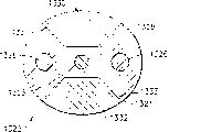
现在参考图9和10,根据本发明的光纤压力传感器第一实施例122包括具有一个或多个光栅(未示出)的芯123。该芯被产生双折射的第一椭圆形覆层126包围。第一覆层126被第二圆柱覆层128包围,第二圆柱覆层128具有两个纵向圆柱侧孔130、132,把各向同性压力转换为各向异性压力。根据图9所示实施例,芯123、第一覆层126、第二覆层128、以及侧孔130、132设置成与它们的纵轴在同一平面内,而且与第一覆层126的短轴在同一平面内。图10中所示另一第一实施例122a与实施例122基本相同,类似的参考标号表示类似的部件,但是第一覆层126a的长轴位于同一平面内。当用于压力传感系统中时,例如图1所示的系统中,光纤122、122a表现出的分辨率和动态范围提高了。特别是,光纤122、122a能够提供好的压力分辨率,动态范围为0psi至至少10kpsi。Referring now to Figures 9 and 10, a
现在参考图11,根据本发明的光纤压力传感器第二实施例222包括具有一个或多个光栅(未示出)的芯223。该芯223具有覆层228,覆层228具有一对双折射发生棒226、226′以及一对纵向圆柱侧孔230、232,把各向同性压力转换为各向异性压力。如图11所示,芯223、覆层228、以及应力发生棒226、226′设置成它们的纵轴在同一个第一平面内;而芯223、覆层228、以及纵向侧孔230、232的纵轴位于与第一平面垂直的第二平面内。当用于如图1所示的压力传感系统时,光纤压力传感器222表现出增强的分辨率和动态范围。Referring now to FIG. 11, a
现在参考图12,光纤压力传感器的第三实施例322与第二实施例222类似,类似的参考标号表示类似的部件。然而,根据该实施例,侧孔330、332不是圆柱形,而是具有C形截面,把各向同性的力转换为集中在芯323上的各向异性的力。在图13所示的另一第三实施例322a与实施例322类似,类似的参考标号表示类似的部件。根据该实施例,侧孔330a、332a具有V性截面,把各向同性的力转换为集中在芯323a上的各向异性的力。当用于如图1所示的压力传感系统中时,光纤压力传感器322、322a的分辨率和动态范围提高了。Referring now to FIG. 12, a
图14示出的光纤压力传感器第四实施例422与第二实施例222类似,类似的参考标号表示类似部件。然而根据该实施例,侧孔430、432的尺寸和位置是非对称的。特别是,侧孔432的截面直径小于侧孔430的截面直径。此外,侧孔432的纵轴不与侧孔430和芯423共面。当用于如图1所示的压力传感系统中时,光纤压力传感器422的分辨率和动态范围提高了。The fourth embodiment 422 of the fiber optic pressure sensor shown in FIG. 14 is similar to the
现在参考图15,根据本发明的光纤压力传感器第五实施例522包括具有芯523的PM光纤521,芯523设置有一个或多个光栅524和一对应力发生棒(未示出)。把PM光纤521插入毛细管525中,毛细管525具有两个纵向圆柱形侧孔530、532,把各向同性的力转换为各向异性的力。侧孔的端部堵上环氧树脂531a、531b、533a、533b或以其他适当的方式密封。当用于如图1所示的压力传感系统中时,光纤压力传感器522的分辨率和动态范围提高了。Referring now to Figure 15, a fifth embodiment 522 of a fiber optic pressure sensor according to the present invention comprises a PM fiber 521 having a core 523 provided with one or more gratings 524 and a pair of stress generating rods (not shown). The PM fiber 521 is inserted into a capillary 525, which has two longitudinal cylindrical side holes 530, 532, converting isotropic forces to anisotropic forces. The ends of the side holes are plugged with epoxy resin 531a, 531b, 533a, 533b or sealed in other suitable ways. When used in a pressure sensing system as shown in FIG. 1, the resolution and dynamic range of the fiber optic pressure sensor 522 are increased.
光纤压力传感器第六实施例622示于图16中。根据该实施例,PM光纤621的芯623上刻有一个或多个光栅624,PM光纤621具有大尺寸覆层628,覆层628具有大尺寸侧孔630、632。通过把光纤621切成具有相同的大尺寸直径的两根单模光纤640、642,以便密封侧孔。然后把单模光纤的端部切成通讯级光纤644、646。当用于如图1所示的压力传感系统中时,光纤压力传感器622的分辨率和动态范围提高了。A sixth embodiment 622 of a fiber optic pressure sensor is shown in FIG. 16 . According to this embodiment, one or more gratings 624 are engraved on the core 623 of the PM fiber 621 , the PM fiber 621 has a cladding 628 with large dimensions, and the cladding 628 has side holes 630 , 632 with large dimensions. The side holes are sealed by cutting the fiber 621 into two single mode fibers 640, 642 having the same major diameter. The ends of the single mode fiber are then cut into communication grade fibers 644,646. When used in a pressure sensing system as shown in FIG. 1, the resolution and dynamic range of the fiber optic pressure sensor 622 are increased.
现在参考图17,光纤压力传感器第七实施例722包括具有带一个或多个光栅(未示出)的芯723的PM光纤721、包围芯的第一椭圆形覆层726、以及包围第一覆层的第二覆层728。第二覆层具有非对称的侧孔730、732并安装在硬衬底材料750中,它的部分表面暴露在外面。柔性隔板752安装在衬底材料750上并覆盖覆层728的暴露部分。施加在隔板752上的压力变换为芯723中的横向应变。当用于如图1所示的压力传感系统中时,光纤压力传感器722的分辨率和动态范围提高了。Referring now to FIG. 17, a seventh embodiment 722 of a fiber optic pressure sensor includes a PM fiber 721 having a core 723 with one or more gratings (not shown), a first elliptical cladding 726 surrounding the core, and a first cladding 726 surrounding the first cladding. layer of the second coating 728 . The second cladding has asymmetric side holes 730, 732 and is mounted in a hard backing material 750 with part of its surface exposed. A flexible spacer 752 is mounted on the substrate material 750 and covers the exposed portions of the cladding 728 . The pressure exerted on the diaphragm 752 is transformed into a transverse strain in the core 723 . When used in a pressure sensing system as shown in FIG. 1, the resolution and dynamic range of the fiber optic pressure sensor 722 are increased.
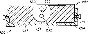
图18示出光纤压力传感器第八实施例822,包括带一个或多个光栅(未示出)的芯823的单模光纤821以及具有一对侧孔830、832的覆层828。覆层828安装在硬衬底材料850中,它的部分表面暴露在外面。柔性隔板852安装在衬底材料850上并覆盖覆层828的暴露部分。衬底材料850安装在机械装置854中(诸如夹具或虎钳),机械装置854在衬底材料850、覆层828、以及芯823中产生压力,以便在芯中产生双折射。施加在隔板852上的压力变换为芯823中的横向应变。当用于如图1所示的压力传感系统中时,光纤压力传感器822的分辨率和动态范围提高了。Figure 18 shows an
现在参考图19,光纤压力传感器第九实施例922包括带一个或多个光栅(未示出)的芯923的单模光纤921以及具有一对侧孔930、932的覆层928。覆层928卷入一块熔点相对覆层低的玻璃950中,暴出覆层的部分表面。玻璃作为在芯923中产生双折射的应力发生元件。施加在覆层暴露表面上的压力变换为芯923中的横向应变。隔板(未示出)可以安装在玻璃上覆盖覆层的暴露表面。当用于如图1所示的压力传感系统中时,光纤压力传感器922的分辨率和动态范围提高了。Referring now to FIG. 19 , a fiber optic pressure sensor ninth embodiment 922 includes a single mode optical fiber 921 with a core 923 with one or more gratings (not shown) and a cladding 928 with a pair of side holes 930 , 932 . The cladding 928 is entrained in a piece of glass 950 which has a lower melting temperature than the cladding, exposing portions of the cladding surface. The glass acts as a stress-generating element that creates birefringence in the core 923 . The pressure exerted on the exposed surface of the cladding is transformed into a transverse strain in the core 923 . A spacer (not shown) may be mounted on the glass over the exposed surface of the cladding. When used in a pressure sensing system as shown in FIG. 1, the resolution and dynamic range of the fiber optic pressure sensor 922 are increased.
图20示出光纤压力传感器第十实施例1022,包括带一个或多个光栅(未示出)的芯1023的单模光纤1021以及具有一对侧孔1030、1032的覆层1028。覆层1028支撑在硬衬底材料1050上,使得具有V形槽1051和杠杆臂1052的板安装在覆层1028的上方。施加在杠杆臂1052左右端上的压力变换为芯1023中的横向应变。当用于如图1所示的压力传感系统中时,光纤压力传感器1022的分辨率和动态范围提高了。Figure 20 shows a tenth embodiment 1022 of a fiber optic pressure sensor comprising a single mode optical fiber 1021 with a core 1023 with one or more gratings (not shown) and a cladding 1028 with a pair of side holes 1030,1032. The cladding 1028 is supported on a hard substrate material 1050 such that a plate with a V-groove 1051 and a lever arm 1052 is mounted over the cladding 1028 . The pressure exerted on the left and right ends of the lever arm 1052 is transformed into a transverse strain in the core 1023 . When used in a pressure sensing system as shown in FIG. 1, the resolution and dynamic range of the fiber optic pressure sensor 1022 are increased.
现在参考图21,光纤压力传感器第十一实施例1122包括带一个或多个光栅(未示出)的芯1123的单模光纤1121以及具有一对侧孔1130、1132的覆层1128。覆层1128插入熔点相对覆层低的玻璃毛细管套1150中。加热玻璃1150并卷成椭圆形玻璃外鞘。玻璃鞘作为在芯1123中产生双折射的应变发生元件,所述芯假设呈椭圆形横截面。在加热并卷完玻璃外鞘之后侧孔1130、1132也呈椭圆形横截面。施加在鞘1150上的压力变换为芯1123中的横向应变。如图21所示,鞘1150形成为使得它的椭圆横截面长轴位于包括芯1123和侧孔1130、1132的纵轴的同一平面内。另一第十一实施例1122a示于图22中,其中类似的参考标号表示类似的部件。如图22所示,鞘1150a形成为使得它的椭圆横截面短轴位于包括芯1123a和侧孔1130a、1132a的纵轴的同一平面内。当用于如图1所示的压力传感系统中时,光纤压力传感器1122和1122a的分辨率和动态范围提高了。Referring now to FIG. 21 , an eleventh embodiment 1122 of a fiber optic pressure sensor includes a single mode optical fiber 1121 with a core 1123 with one or more gratings (not shown) and a cladding 1128 with a pair of side holes 1130 , 1132 . The cladding 1128 is inserted into a glass capillary sleeve 1150 having a lower melting point than the cladding. The glass 1150 is heated and rolled into an oval glass sheath. The glass sheath acts as a strain generating element that creates birefringence in the core 1123, which assumes an elliptical cross-section. The side holes 1130, 1132 also have an oval cross-section after heating and rolling the glass sheath. The pressure exerted on the sheath 1150 translates into a transverse strain in the core 1123 . As shown in FIG. 21 , the sheath 1150 is formed such that its elliptical cross-sectional major axis lies in the same plane including the longitudinal axes of the core 1123 and side holes 1130 , 1132 . Another eleventh embodiment 1122a is shown in Figure 22, wherein like reference numerals refer to like parts. As shown in FIG. 22, sheath 1150a is formed such that the minor axis of its elliptical cross-section lies in the same plane that includes the longitudinal axes of core 1123a and side holes 1130a, 1132a. When used in a pressure sensing system as shown in FIG. 1, the resolution and dynamic range of the fiber optic pressure sensors 1122 and 1122a are increased.
图23示出光纤压力传感器第十二实施例1222,包括带一个或多个光栅(未示出)芯1223的PM光纤1221,和具有一对纵向应力发生棒1126、1126′的覆层1228。一对毛细管1260、1262每个都具有端盖1260a、1260b、1262a、1262b,粘在覆层228的侧面。当用于如图1所示的压力传感系统中时,光纤压力传感器1222的分辨率和动态范围提高了。Figure 23 shows a
现在参考图24和25,光纤压力传感器第十三实施例1322包括带一个或多个光栅1324的芯1323的PM光纤1321以及具有一对纵向应力发生棒1326、1326′的覆层1328。覆层1328的两部分1331、1333被磨掉或刻蚀掉并注入压力敏感材料1330、1332,即比覆层对压力更为敏感的材料例如尼龙。施加在材料1330、1332的压力变换为芯1323中的横向应变。当用于如图1所示的压力传感系统中时,光纤压力传感器1322的分辨率和动态范围提高了。Referring now to Figures 24 and 25, a thirteenth embodiment of a fiber
这里已经描述和说明了分辨率和动态范围增强的光纤压力传感器和利用这种传感器的光纤压力传感系统的几个实施例。虽然描述了本发明的特定实施例,但是本发明并不限于此,本发明的范围意欲如同技术所允许的一样宽,说明书的意思也是如此。例如,公开的压力传感系统只是利用光纤压力传感器的示范系统。本领域的技术人员将理解本发明的光纤压力传感器也可以很好地应用在其他类型的压力传感系统中。此外,将理解可以在单个光波导中应用多个光栅以便通过单个波导测量不同位置的压力。本领域的技术人员将进一步理解根据本发明的小光纤压力传感器可以切成通讯光纤并放置在相对远离光谱分析仪的探测点上。因此,本领域的技术人员可以理解能够对本发明进行其他改进,而不脱离本发明权利要求的精神和范围。Several embodiments of fiber optic pressure sensors with enhanced resolution and dynamic range and fiber optic pressure sensing systems utilizing such sensors have been described and illustrated herein. While particular embodiments of the invention have been described, the invention is not limited thereto, and the scope of the invention is intended to be as broad as the technology will allow, and so is the meaning of the specification. For example, the disclosed pressure sensing systems are merely exemplary systems utilizing fiber optic pressure sensors. Those skilled in the art will understand that the fiber optic pressure sensor of the present invention can also be well used in other types of pressure sensing systems. Furthermore, it will be appreciated that multiple gratings may be employed in a single optical waveguide in order to measure pressure at different locations through a single waveguide. Those skilled in the art will further understand that the small optical fiber pressure sensor according to the present invention can be cut into a communication optical fiber and placed at a detection point relatively far from the optical spectrum analyzer. Therefore, those skilled in the art can understand that other modifications can be made to the present invention without departing from the spirit and scope of the claims of the present invention.
Claims (25)
Applications Claiming Priority (3)
| Application Number | Priority Date | Filing Date | Title |
|---|---|---|---|
| US08/888,566 | 1997-07-07 | ||
| US08/888,566 US5841131A (en) | 1997-07-07 | 1997-07-07 | Fiber optic pressure transducers and pressure sensing system incorporating same |
| US08/888566 | 1997-07-07 |
Publications (2)
| Publication Number | Publication Date |
|---|---|
| CN1269881A CN1269881A (en) | 2000-10-11 |
| CN1135373C true CN1135373C (en) | 2004-01-21 |
Family
ID=25393424
Family Applications (1)
| Application Number | Title | Priority Date | Filing Date |
|---|---|---|---|
| CNB988089106A Expired - Fee Related CN1135373C (en) | 1997-07-07 | 1998-07-02 | Fiber optic pressure sensor and pressure sensing system including such a pressure sensor |
Country Status (10)
| Country | Link |
|---|---|
| US (1) | US5841131A (en) |
| EP (1) | EP0995091A1 (en) |
| JP (1) | JP2002504663A (en) |
| CN (1) | CN1135373C (en) |
| AU (1) | AU8288398A (en) |
| CA (1) | CA2295919A1 (en) |
| ID (1) | ID26513A (en) |
| NO (1) | NO20000039L (en) |
| RU (1) | RU2205374C2 (en) |
| WO (1) | WO1999002953A1 (en) |
Cited By (1)
| Publication number | Priority date | Publication date | Assignee | Title |
|---|---|---|---|---|
| CN101501466B (en) * | 2006-07-07 | 2012-04-04 | 莱尼股份公司 | Sensor system, sensor element and method for monitoring a closing mechanism |
Families Citing this family (131)
| Publication number | Priority date | Publication date | Assignee | Title |
|---|---|---|---|---|
| US6218661B1 (en) * | 1996-09-09 | 2001-04-17 | Schlumberger Technology Corporation | Methods and apparatus for mechanically enhancing the sensitivity of transversely loaded fiber optic sensors |
| US6144026A (en) * | 1997-10-17 | 2000-11-07 | Blue Road Research | Fiber optic grating corrosion and chemical sensor |
| US6335524B1 (en) | 1997-10-22 | 2002-01-01 | Blue Road Research | High speed demodulation systems for fiber optic grating sensors |
| NO313024B1 (en) * | 1997-12-19 | 2002-07-29 | Optoplan As | Method for using an optical fiber as hydrostatic pressure foil |
| US6385368B1 (en) * | 1998-02-20 | 2002-05-07 | Lucent Technologies, Inc. | Method and apparatus for modulating signal strength within optical systems |
| DE19807891A1 (en) * | 1998-02-25 | 1999-08-26 | Abb Research Ltd | Fiber-laser sensor for measurement of elongation, temperature or especially isotropic pressure in oil well |
| US6208776B1 (en) * | 1998-04-08 | 2001-03-27 | Physical Optics Corporation | Birefringent fiber grating sensor and detection system |
| US6072922A (en) * | 1998-06-19 | 2000-06-06 | Science And Engineering Applications Company, Inc. | Cryogenic fiber optic temperature sensor |
| US6249624B1 (en) | 1998-12-04 | 2001-06-19 | Cidra Corporation | Method and apparatus for forming a Bragg grating with high intensity light |
| US6298184B1 (en) | 1998-12-04 | 2001-10-02 | Cidra Corporation | Method and apparatus for forming a tube-encased bragg grating |
| US6452667B1 (en) | 1998-12-04 | 2002-09-17 | Weatherford/Lamb Inc. | Pressure-isolated bragg grating temperature sensor |
| US6865194B1 (en) | 1998-12-04 | 2005-03-08 | Cidra Corporation | Strain-isolated Bragg grating temperature sensor |
| AU756444B2 (en) | 1998-12-04 | 2003-01-16 | Weatherford Technology Holdings, Llc | Bragg grating pressure sensor |
| JP4522588B2 (en) * | 1998-12-04 | 2010-08-11 | シドラ コーポレイション | Compression-tuned Bragg grating and laser |
| US6229827B1 (en) | 1998-12-04 | 2001-05-08 | Cidra Corporation | Compression-tuned bragg grating and laser |
| US6278811B1 (en) | 1998-12-04 | 2001-08-21 | Arthur D. Hay | Fiber optic bragg grating pressure sensor |
| CA2353504C (en) * | 1998-12-04 | 2007-09-11 | Cidra Corporation | Compression-tuned bragg grating and laser |
| DE69923783D1 (en) | 1998-12-04 | 2005-03-24 | Weatherford Lamb | PRESSURE SENSOR WITH BRAGG GRILLE |
| US6982996B1 (en) * | 1999-12-06 | 2006-01-03 | Weatherford/Lamb, Inc. | Large diameter optical waveguide, grating, and laser |
| US6490931B1 (en) | 1998-12-04 | 2002-12-10 | Weatherford/Lamb, Inc. | Fused tension-based fiber grating pressure sensor |
| US6810178B2 (en) * | 1998-12-04 | 2004-10-26 | Cidra Corporation | Large diameter optical waveguide having blazed grating therein |
| AU757885B2 (en) | 1998-12-04 | 2003-03-13 | Cidra Corporation | Tube-encased fiber grating |
| US6271766B1 (en) | 1998-12-23 | 2001-08-07 | Cidra Corporation | Distributed selectable latent fiber optic sensors |
| DE60025766T2 (en) * | 1999-02-19 | 2006-10-12 | Crystal Fibre A/S | Production process of a photonic crystal fiber |
| DE19939583A1 (en) * | 1999-02-24 | 2000-09-14 | Siemens Ag | Bragg grating device to measure mechanical force, e.g. for vibration sensor |
| US6233746B1 (en) | 1999-03-22 | 2001-05-22 | Halliburton Energy Services, Inc. | Multiplexed fiber optic transducer for use in a well and method |
| US6363180B1 (en) | 1999-04-30 | 2002-03-26 | Schlumberger Technology Corporation | Methods and apparatus for enhancing dynamic range, sensitivity, accuracy, and resolution in fiber optic sensor systems |
| US6246048B1 (en) * | 1999-05-18 | 2001-06-12 | Schlumberger Technology Corporation | Methods and apparatus for mechanically enhancing the sensitivity of longitudinally loaded fiber optic sensors |
| US6996316B2 (en) * | 1999-09-20 | 2006-02-07 | Cidra Corporation | Large diameter D-shaped optical waveguide and coupler |
| US6439055B1 (en) | 1999-11-15 | 2002-08-27 | Weatherford/Lamb, Inc. | Pressure sensor assembly structure to insulate a pressure sensing device from harsh environments |
| US6626043B1 (en) * | 2000-01-31 | 2003-09-30 | Weatherford/Lamb, Inc. | Fluid diffusion resistant glass-encased fiber optic sensor |
| US6506313B1 (en) * | 2000-02-01 | 2003-01-14 | Pacific Wave Industries, Inc. | Ultraminiature fiber optic pressure transducer and method of fabrication |
| US6304686B1 (en) | 2000-02-09 | 2001-10-16 | Schlumberger Technology Corporation | Methods and apparatus for measuring differential pressure with fiber optic sensor systems |
| US6946645B2 (en) * | 2000-12-20 | 2005-09-20 | Schlumberger Technology Corporation | Measuring system with sweeping comb filter and multiplexer |
| ES2388324T3 (en) * | 2000-12-22 | 2012-10-11 | Vestas Wind Systems A/S | Fiber optic extensometer and manufacturing procedure of said extensometer |
| NO316775B1 (en) * | 2001-06-11 | 2004-05-03 | Optoplan As | Method of Coating a Fiber with Fiber Optic Bragg Grids (FBG) |
| US6658171B2 (en) | 2001-06-14 | 2003-12-02 | Ericsson Telecomunicacoes S.A. | Optical fiber bragg grating polarizer |
| SE0102613D0 (en) * | 2001-07-25 | 2001-07-25 | Proximion Fiber Optics Ab | Fiber optical grating |
| US20030039747A1 (en) * | 2001-08-27 | 2003-02-27 | Optinel Systems,Inc. | Method of enhancing waveguide photosensitivity and waveguide having enhanced photosensitivity |
| EP1442323A1 (en) * | 2001-10-09 | 2004-08-04 | Crystal Fibre A/S | Hermetically sealed optical fibre with voids or holes, method of its production, and its use |
| AU2003229545A1 (en) * | 2002-05-23 | 2003-12-12 | Crystal Fibre A/S | Optical waveguide, method of its production, and its use |
| US7062126B2 (en) * | 2002-06-07 | 2006-06-13 | Kersey Alan D | Tunable optical filter having large diameter optical waveguide with bragg grating and being configured for reducing the bulk modulus of compressibility thereof |
| US20030234921A1 (en) | 2002-06-21 | 2003-12-25 | Tsutomu Yamate | Method for measuring and calibrating measurements using optical fiber distributed sensor |
| WO2004023171A2 (en) * | 2002-09-06 | 2004-03-18 | Virginia Tech Intellectual Properties, Inc. | Intrinsic fabry-perot optical fiber sensors and their multiplexing |
| US6898339B2 (en) * | 2002-12-16 | 2005-05-24 | Schlumberger Technology Corporation | Multiple mode pre-loadable fiber optic pressure and temperature sensor |
| US6931188B2 (en) * | 2003-02-21 | 2005-08-16 | Weatherford/Lamb, Inc. | Side-hole cane waveguide sensor |
| US7200309B2 (en) * | 2003-06-19 | 2007-04-03 | Corning Incorporated | Single polarization and polarization maintaining optical fibers and system utilizing same |
| WO2004113978A1 (en) * | 2003-06-19 | 2004-12-29 | Corning Incorporated | Single polarization optical fiber and system and method for producing same |
| EP1700146B1 (en) * | 2003-12-19 | 2013-04-10 | NKT Photonics A/S | Photonic crystal fibres comprising stress elements |
| US7196318B2 (en) * | 2004-07-16 | 2007-03-27 | Kin-Man Yip | Fiber-optic sensing system |
| US20120014637A1 (en) * | 2004-09-08 | 2012-01-19 | Yasuyuki Hishida | Shock detection optical fiber sensor |
| US20060197012A1 (en) * | 2005-03-04 | 2006-09-07 | Eric Udd | Shear and pressure/transverse strain fiber grating sensors |
| GB2427910B (en) * | 2005-07-02 | 2008-03-12 | Sensor Highway Ltd | Fiber optic temperature and pressure sensor and system incorporating same |
| US7171091B1 (en) * | 2005-08-15 | 2007-01-30 | The United States Of America As Represented By The Secretary Of The Air Force | Tuned cladding fiber amplifier and laser |
| RU2319988C2 (en) * | 2005-10-31 | 2008-03-20 | Общество с ограниченной ответственностью "Инверсия-Сенсор" | Fiber-optic multiple sensor system, temperature/deformation detector for fiber-optic multiple sensor system, and method of recording of detector (versions) |
| US7382957B2 (en) * | 2006-01-30 | 2008-06-03 | Corning Incorporated | Rare earth doped double clad optical fiber with plurality of air holes and stress rods |
| US8573313B2 (en) * | 2006-04-03 | 2013-11-05 | Schlumberger Technology Corporation | Well servicing methods and systems |
| US20080118214A1 (en) * | 2006-04-20 | 2008-05-22 | Peng Chen | Optical fiber for detecting stress and associated method |
| US7412142B2 (en) * | 2006-05-19 | 2008-08-12 | Corning Incorporated | Optical fiber with plurality of air holes and stress rods |
| US7310456B1 (en) * | 2006-06-02 | 2007-12-18 | Baker Hughes Incorporated | Multi-core optical fiber pressure sensor |
| US7510011B2 (en) * | 2006-07-06 | 2009-03-31 | Schlumberger Technology Corporation | Well servicing methods and systems employing a triggerable filter medium sealing composition |
| GB2454613B (en) * | 2006-08-16 | 2011-05-25 | Schlumberger Holdings | Fiber-optic transducer for fluid and/or gas velocity measure ment |
| JP4923960B2 (en) * | 2006-10-31 | 2012-04-25 | 日立電線株式会社 | Shock detection optical fiber sensor |
| US8417084B2 (en) * | 2007-01-16 | 2013-04-09 | Baker Hughes Incorporated | Distributed optical pressure and temperature sensors |
| US7840102B2 (en) | 2007-01-16 | 2010-11-23 | Baker Hughes Incorporated | Distributed optical pressure and temperature sensors |
| DE102007008464B4 (en) * | 2007-02-19 | 2012-01-05 | Hottinger Baldwin Messtechnik Gmbh | Optical strain gauge |
| JP2008224413A (en) * | 2007-03-13 | 2008-09-25 | Denso Corp | Printed board manufacturing device and printed board manufacturing method |
| US20090028489A1 (en) * | 2007-07-17 | 2009-01-29 | Eric Udd | High speed fiber optic grating sensor system |
| EP2073000A1 (en) | 2007-12-20 | 2009-06-24 | Nederlandse Organisatie voor toegepast- natuurwetenschappelijk onderzoek TNO | Coated waveguide for optical detection |
| EP2075549A1 (en) | 2007-12-28 | 2009-07-01 | Nederlandse Organisatie voor toegepast- natuurwetenschappelijk onderzoek TNO | Shape memory sensor |
| JP2012503207A (en) * | 2008-09-23 | 2012-02-02 | フォイト パテント ゲゼルシャフト ミット ベシュレンクテル ハフツング | Industrial roll with optical roll cover sensor system |
| EP2202548A1 (en) | 2008-12-23 | 2010-06-30 | Nederlandse Organisatie voor Toegepast-Natuurwetenschappelijk Onderzoek TNO | Distributed optical chemical sensor |
| US9188256B2 (en) * | 2009-10-05 | 2015-11-17 | National Oilwell Varco Denmark I/S | Flexible unbonded oil pipe system with an optical fiber sensor inside |
| US8849073B2 (en) | 2009-10-12 | 2014-09-30 | Schlumberger Technology Corporation | Pressure and measurement by means of an optical fiber |
| WO2011060817A1 (en) * | 2009-11-19 | 2011-05-26 | Vrije Universiteit Brussel | Optical fiber structure for sensors |
| US8326095B2 (en) * | 2010-02-08 | 2012-12-04 | Schlumberger Technology Corporation | Tilt meter including optical fiber sections |
| US8369671B2 (en) * | 2010-02-26 | 2013-02-05 | General Electric Company | Hermetically sealed fiber sensing cable |
| GB201019117D0 (en) | 2010-11-11 | 2010-12-29 | Fotech Solutions Ltd | Distributed optical fibre sensor |
| US9557239B2 (en) * | 2010-12-03 | 2017-01-31 | Baker Hughes Incorporated | Determination of strain components for different deformation modes using a filter |
| US9103736B2 (en) | 2010-12-03 | 2015-08-11 | Baker Hughes Incorporated | Modeling an interpretation of real time compaction modeling data from multi-section monitoring system |
| EP2500314A1 (en) | 2011-03-14 | 2012-09-19 | Nederlandse Organisatie voor toegepast -natuurwetenschappelijk onderzoek TNO | Photonic crystal sensor |
| CN102261978B (en) * | 2011-04-28 | 2013-01-30 | 浙江师范大学 | Method and device for realizing hydraulic pressure sensing based on double-core double-hole optical fiber |
| US9417103B2 (en) | 2011-09-20 | 2016-08-16 | Schlumberger Technology Corporation | Multiple spectrum channel, multiple sensor fiber optic monitoring system |
| CN103162878B (en) * | 2011-12-11 | 2015-12-09 | 黄辉 | A kind of fibre optic compression sensor and preparation method thereof |
| CN102868447B (en) * | 2012-09-24 | 2015-07-15 | 深圳太辰光通信股份有限公司 | Fiber grating tracker and fault detection method of optical fiber circuit |
| AT513732B1 (en) * | 2012-11-27 | 2015-05-15 | Fct Fiber Cable Technology Gmbh | Method for spatially resolved pressure measurement |
| US20160025584A1 (en) * | 2013-01-16 | 2016-01-28 | Omnisens Sa | A sensing cable |
| WO2014176522A1 (en) * | 2013-04-26 | 2014-10-30 | Wicor Holding Ag | Fiber-grating sensors having longitudinal-strain-inducing jackets and sensor systems and structures including such sensors |
| CN103411727B (en) * | 2013-07-26 | 2015-08-05 | 西北工业大学 | For the tonometric fibre optic compression sensor of pneumatic plant and measuring method thereof |
| CN103983385B (en) * | 2014-05-07 | 2016-05-18 | 王东方 | A kind of method of elliposoidal fibre optic compression sensor and detection fiber fault pressure spot |
| EP3149432B1 (en) | 2014-05-28 | 2019-02-20 | Nederlandse Organisatie voor toegepast- natuurwetenschappelijk onderzoek TNO | A fiber bragg grating optical sensor having a nanoporous coating |
| CN104089725A (en) * | 2014-07-25 | 2014-10-08 | 绵阳彬华科技有限公司 | Temperature sensor stable in structure |
| RU2571448C1 (en) * | 2014-08-05 | 2015-12-20 | Открытое акционерное общество "Научно-исследовательский институт физических измерений" | Micromechanical fibre-optic pressure sensor |
| WO2016070110A1 (en) | 2014-10-31 | 2016-05-06 | Lake Region Medical, Inc. | Fiber bragg grating multi-point pressure sensing guidewire with birefringent component |
| US10267694B2 (en) * | 2016-01-15 | 2019-04-23 | The United States Of America As Represented By The Administrator Of Nasa | Micrometeoroid and orbital debris impact detection and location using fiber optic strain sensing |
| CN106154402B (en) * | 2016-07-04 | 2019-03-29 | 北京航空航天大学 | A kind of low magnetic susceptibility solid core polarization-maintaining photonic crystal fiber based on stress buffer area |
| US20180088360A1 (en) * | 2016-09-29 | 2018-03-29 | Ofs Fitel, Llc | Polarization Maintaining Optical Fiber With Non-Symmetric Stress Applying Parts |
| US9964698B1 (en) * | 2016-10-28 | 2018-05-08 | The Boeing Company | Multicore optical fiber cable strain enhancement |
| RU2628734C1 (en) * | 2016-11-09 | 2017-08-21 | Акционерное общество "Научно-исследовательский институт физических измерений" | Fiber optical pressure sensor |
| CN106709624B (en) * | 2016-11-19 | 2020-07-03 | 国网河南省电力公司周口供电公司 | Intelligent management system for grounding wire |
| US20180360382A1 (en) * | 2017-06-18 | 2018-12-20 | Pixart Imaging Inc. | Optical measurement device with pressure feedback function |
| US10557343B2 (en) | 2017-08-25 | 2020-02-11 | Schlumberger Technology Corporation | Sensor construction for distributed pressure sensing |
| RU2664684C1 (en) * | 2017-09-04 | 2018-08-21 | федеральное государственное бюджетное образовательное учреждение высшего образования "Пермский национальный исследовательский политехнический университет" | Fiber-optic pressure sensor |
| GB2568524B (en) * | 2017-11-20 | 2019-11-06 | Smart Fibres Ltd | A method for forming a pressure sensor |
| CN110006562B (en) * | 2019-02-28 | 2020-11-20 | 北京大学 | Distributed optical fiber sensing system based on mode coupling |
| CN110160685B (en) * | 2019-06-04 | 2024-12-27 | 深圳大学 | Fiber Bragg grating directional pressure sensor, fiber Bragg grating preparation method and device |
| WO2020243896A1 (en) * | 2019-06-04 | 2020-12-10 | 深圳大学 | Optical fiber grating directional pressure sensor, and optical fiber grating preparation method and device |
| CN110296778B (en) * | 2019-06-19 | 2020-07-10 | 华中科技大学 | A kind of passive pressure sensing fiber and preparation method thereof |
| CN110307921B (en) * | 2019-07-02 | 2021-01-22 | 运城学院 | Pressure sensor |
| EP4013338A4 (en) | 2019-08-12 | 2023-08-30 | Bard Access Systems, Inc. | FORM MEASUREMENT SYSTEMS AND PROCESSES FOR MEDICAL DEVICES |
| EP4061466A4 (en) | 2019-11-25 | 2023-11-22 | Bard Access Systems, Inc. | OPTICAL PEAK TRACKING SYSTEMS AND METHODS THEREOF |
| EP4171423B1 (en) | 2020-06-26 | 2026-01-21 | Bard Access Systems, Inc. | Malposition detection system |
| CN113926050A (en) | 2020-06-29 | 2022-01-14 | 巴德阿克塞斯系统股份有限公司 | Automatic dimensional reference system for optical fibers |
| CN216317552U (en) * | 2020-07-10 | 2022-04-19 | 巴德阿克塞斯系统股份有限公司 | Medical device system for detecting damage and potential damage to optical fiber technology of medical devices |
| RU203603U1 (en) * | 2020-12-15 | 2021-04-14 | Федеральное государственное бюджетное образовательное учреждение высшего образования "Казанский национальный исследовательский технический университет им. А.Н. Туполева - КАИ" | FIBER OPTICAL PRESSURE MEASURING DEVICE |
| RU203379U1 (en) * | 2020-12-15 | 2021-04-01 | Федеральное государственное бюджетное образовательное учреждение высшего образования "Казанский национальный исследовательский технический университет им. А.Н. Туполева - КАИ" | Fiber Optic Pressure Monitoring Device |
| RU203788U1 (en) * | 2020-12-15 | 2021-04-21 | Федеральное государственное бюджетное образовательное учреждение высшего образования "Казанский национальный исследовательский технический университет им. А.Н. Туполева - КАИ" | FIBER OPTICAL PRESSURE MEASURING DEVICE |
| CN112924082B (en) * | 2021-01-25 | 2021-09-28 | 广东海洋大学 | High-sensitivity air pressure sensor based on suspension core optical fiber and side hole optical fiber |
| EP4280995A1 (en) | 2021-01-26 | 2023-11-29 | Bard Access Systems, Inc. | Fiber optic shape sensing system associated with port placement |
| CN113029215B (en) * | 2021-03-02 | 2025-07-18 | 西南科技大学 | Photonic crystal fiber structure and optical fiber sensor |
| EP4337091A1 (en) | 2021-05-18 | 2024-03-20 | Bard Access Systems, Inc. | Anatomical oscillation and fluctuation sensing and confirmation system |
| FR3125879B1 (en) | 2021-07-29 | 2024-01-12 | Commissariat Energie Atomique | Device for measuring hydrostatic pressure, in particular absolute and/or temperature, and associated measuring method |
| WO2023076143A1 (en) | 2021-10-25 | 2023-05-04 | Bard Access Systems, Inc. | Reference plane for medical device placement |
| US12343117B2 (en) | 2022-06-28 | 2025-07-01 | Bard Access Systems, Inc. | Fiber optic medical systems and methods for identifying blood vessels |
| US12349984B2 (en) | 2022-06-29 | 2025-07-08 | Bard Access Systems, Inc. | System, method, and apparatus for improved confirm of an anatomical position of a medical instrument |
| CN115077366A (en) * | 2022-07-25 | 2022-09-20 | 苏州市轨道交通集团有限公司 | Three-component fiber grating sensor for detecting dislocation of tube sheet and working method |
| CN121399512A (en) * | 2023-06-23 | 2026-01-23 | 牛津大学创新有限公司 | Optical fiber and use thereof |
| WO2025131752A1 (en) | 2023-12-22 | 2025-06-26 | Commissariat A L'energie Atomique Et Aux Energies Alternatives | Device for measuring force variations, mechanical deformations, hydrostatic pressures and temperature, and associated measurement method |
| FR3157531A1 (en) | 2023-12-22 | 2025-06-27 | Commissariat A L'energie Atomique Et Aux Energies Alternatives | Device for measuring variations in force, mechanical deformations, hydrostatic pressures and temperature, and associated measuring method |
| DE102024122583A1 (en) * | 2024-08-07 | 2026-02-12 | Deutsches Zentrum für Luft- und Raumfahrt e.V. | Continuous pressure measurement using fiber optic measuring technology |
| CN119724043B (en) * | 2024-12-16 | 2025-09-12 | 京东方科技集团股份有限公司 | Display panel, display device, pressure detection method and manufacturing method |
Family Cites Families (11)
| Publication number | Priority date | Publication date | Assignee | Title |
|---|---|---|---|---|
| US4360247A (en) * | 1981-01-19 | 1982-11-23 | Gould Inc. | Evanescent fiber optic pressure sensor apparatus |
| US4659923A (en) * | 1981-03-09 | 1987-04-21 | Polaroid Corporation | Fiber optic interferometer transducer |
| SU1298555A1 (en) * | 1985-06-10 | 1987-03-23 | Военно-воздушная инженерная Краснознаменная академия им.проф.Н.Е.Жуковского | Pressure meter |
| SU1372265A1 (en) * | 1986-06-13 | 1988-02-07 | О.Г.Семенов | Method and device for measuring pressure |
| GB9203471D0 (en) * | 1992-02-19 | 1992-04-08 | Sensor Dynamics Ltd | Optical fibre pressure sensor |
| US5380995A (en) * | 1992-10-20 | 1995-01-10 | Mcdonnell Douglas Corporation | Fiber optic grating sensor systems for sensing environmental effects |
| US5401956A (en) * | 1993-09-29 | 1995-03-28 | United Technologies Corporation | Diagnostic system for fiber grating sensors |
| SE502778C2 (en) * | 1993-10-14 | 1996-01-08 | Ericsson Telefon Ab L M | Optical fiber for use as a sensor and method for producing an optical fiber for use as a sensor |
| FR2715730B1 (en) * | 1994-02-01 | 1996-03-01 | Thomson Csf | Coiled fiber optic pressure sensor. |
| US5591965A (en) * | 1995-05-08 | 1997-01-07 | Udd; Eric | Multiparameter sensor system using a multiple grating fiber optic birefringent fiber |
| US5828059A (en) * | 1996-09-09 | 1998-10-27 | Udd; Eric | Transverse strain measurements using fiber optic grating based sensors |
-
1997
- 1997-07-07 US US08/888,566 patent/US5841131A/en not_active Expired - Lifetime
-
1998
- 1998-07-02 ID IDW20000098A patent/ID26513A/en unknown
- 1998-07-02 EP EP98933155A patent/EP0995091A1/en not_active Withdrawn
- 1998-07-02 CN CNB988089106A patent/CN1135373C/en not_active Expired - Fee Related
- 1998-07-02 WO PCT/US1998/013912 patent/WO1999002953A1/en not_active Ceased
- 1998-07-02 RU RU2000102711/28A patent/RU2205374C2/en not_active IP Right Cessation
- 1998-07-02 JP JP2000502386A patent/JP2002504663A/en active Pending
- 1998-07-02 AU AU82883/98A patent/AU8288398A/en not_active Abandoned
- 1998-07-02 CA CA002295919A patent/CA2295919A1/en not_active Abandoned
-
2000
- 2000-01-05 NO NO20000039A patent/NO20000039L/en not_active Application Discontinuation
Cited By (1)
| Publication number | Priority date | Publication date | Assignee | Title |
|---|---|---|---|---|
| CN101501466B (en) * | 2006-07-07 | 2012-04-04 | 莱尼股份公司 | Sensor system, sensor element and method for monitoring a closing mechanism |
Also Published As
| Publication number | Publication date |
|---|---|
| CN1269881A (en) | 2000-10-11 |
| AU8288398A (en) | 1999-02-08 |
| RU2205374C2 (en) | 2003-05-27 |
| CA2295919A1 (en) | 1999-01-21 |
| US5841131A (en) | 1998-11-24 |
| ID26513A (en) | 2001-01-11 |
| WO1999002953A1 (en) | 1999-01-21 |
| EP0995091A1 (en) | 2000-04-26 |
| NO20000039L (en) | 2000-03-07 |
| JP2002504663A (en) | 2002-02-12 |
| NO20000039D0 (en) | 2000-01-05 |
Similar Documents
| Publication | Publication Date | Title |
|---|---|---|
| CN1135373C (en) | Fiber optic pressure sensor and pressure sensing system including such a pressure sensor | |
| US6218661B1 (en) | Methods and apparatus for mechanically enhancing the sensitivity of transversely loaded fiber optic sensors | |
| CA2612385C (en) | Fiber optic temperature and pressure sensor and system incorporating same | |
| US6304686B1 (en) | Methods and apparatus for measuring differential pressure with fiber optic sensor systems | |
| CN1155798C (en) | fiber grating transverse strain sensor system | |
| US6246048B1 (en) | Methods and apparatus for mechanically enhancing the sensitivity of longitudinally loaded fiber optic sensors | |
| US6647800B2 (en) | Temperature insensitive fiber-optic torque and strain sensor | |
| US8849073B2 (en) | Pressure and measurement by means of an optical fiber | |
| EP1175599B1 (en) | Methods and apparatus for enhancing dynamic range, sensitivity, accuracy, and resolution in fiber optic sensor systems | |
| GB2396409A (en) | Fiber optic pressure & temperature sensor including a diaphragm and a compression element | |
| Qi | A comparison study of the sensing characteristics of FBG and TFBG | |
| US5589931A (en) | System to determine environmental pressure and birefringent-biased cladded optical sensor for use therein | |
| Rajan | Introduction to optical fiber sensors | |
| Flockhart et al. | Differential phase tracking applied to Bragg gratings in multi-core fibre for high accuracy curvature measurement | |
| Fuhr et al. | A novel signal demodulation technique for chirped Bragg grating strain sensors | |
| Lu et al. | Fiber-optic micro-displacement sensor probe based on Vernier effect | |
| MXPA00000257A (en) | Fiber optic pressure transducers and pressure sensing system incorporating same | |
| Zheng et al. | Temperature-insensitive 2D inclinometer based on pendulum-assisted fiber Bragg gratings | |
| Pan et al. | A high-precision axial strain measurement sensor utilizing misaligned thin-core fiber | |
| Zhang et al. | Temperature-independent FBG-type torsion sensor | |
| Dabkiewicz et al. | Fiber-Optic Pressure Sensor Using Birefringence In Side-Hole Fiber | |
| Dong et al. | Novel fiber Bragg grating sensor for temperature-insensitive displacement measurement | |
| Coppola et al. | Detecting vibrations by fiber Bragg sensor interrogated with a bipolished silicon sample | |
| Rao et al. | PCF-based Fabry-Perot refractive-index sensor | |
| Ramakrishnan et al. | Design of a surface attachable hybrid fiber sensor packaged in a polyimide film for engineering applications |
Legal Events
| Date | Code | Title | Description |
|---|---|---|---|
| C06 | Publication | ||
| PB01 | Publication | ||
| C10 | Entry into substantive examination | ||
| SE01 | Entry into force of request for substantive examination | ||
| C14 | Grant of patent or utility model | ||
| GR01 | Patent grant | ||
| C19 | Lapse of patent right due to non-payment of the annual fee | ||
| CF01 | Termination of patent right due to non-payment of annual fee |