CN113520552B - Amnion membrane rupture device suitable for gynaecology and obstetrics - Google Patents
Amnion membrane rupture device suitable for gynaecology and obstetrics Download PDFInfo
- Publication number
- CN113520552B CN113520552B CN202110840571.6A CN202110840571A CN113520552B CN 113520552 B CN113520552 B CN 113520552B CN 202110840571 A CN202110840571 A CN 202110840571A CN 113520552 B CN113520552 B CN 113520552B
- Authority
- CN
- China
- Prior art keywords
- cylinder
- ring
- cutter head
- seat
- adsorption
- Prior art date
- Legal status (The legal status is an assumption and is not a legal conclusion. Google has not performed a legal analysis and makes no representation as to the accuracy of the status listed.)
- Active
Links
Images


Classifications
-
- A—HUMAN NECESSITIES
- A61—MEDICAL OR VETERINARY SCIENCE; HYGIENE
- A61B—DIAGNOSIS; SURGERY; IDENTIFICATION
- A61B17/00—Surgical instruments, devices or methods
- A61B17/42—Gynaecological or obstetrical instruments or methods
- A61B17/4208—Instruments for rupturing the amniotic membrane
-
- A—HUMAN NECESSITIES
- A61—MEDICAL OR VETERINARY SCIENCE; HYGIENE
- A61B—DIAGNOSIS; SURGERY; IDENTIFICATION
- A61B90/00—Instruments, implements or accessories specially adapted for surgery or diagnosis and not covered by any of the groups A61B1/00 - A61B50/00, e.g. for luxation treatment or for protecting wound edges
- A61B90/08—Accessories or related features not otherwise provided for
- A61B2090/0801—Prevention of accidental cutting or pricking
- A61B2090/08021—Prevention of accidental cutting or pricking of the patient or his organs
-
- A—HUMAN NECESSITIES
- A61—MEDICAL OR VETERINARY SCIENCE; HYGIENE
- A61B—DIAGNOSIS; SURGERY; IDENTIFICATION
- A61B2217/00—General characteristics of surgical instruments
- A61B2217/002—Auxiliary appliance
- A61B2217/005—Auxiliary appliance with suction drainage system
-
- A—HUMAN NECESSITIES
- A61—MEDICAL OR VETERINARY SCIENCE; HYGIENE
- A61B—DIAGNOSIS; SURGERY; IDENTIFICATION
- A61B2217/00—General characteristics of surgical instruments
- A61B2217/002—Auxiliary appliance
- A61B2217/007—Auxiliary appliance with irrigation system
Landscapes
- Health & Medical Sciences (AREA)
- Surgery (AREA)
- Life Sciences & Earth Sciences (AREA)
- Biomedical Technology (AREA)
- Medical Informatics (AREA)
- Veterinary Medicine (AREA)
- Public Health (AREA)
- Engineering & Computer Science (AREA)
- General Health & Medical Sciences (AREA)
- Heart & Thoracic Surgery (AREA)
- Nuclear Medicine, Radiotherapy & Molecular Imaging (AREA)
- Molecular Biology (AREA)
- Animal Behavior & Ethology (AREA)
- Gynecology & Obstetrics (AREA)
- Pregnancy & Childbirth (AREA)
- Reproductive Health (AREA)
- Oral & Maxillofacial Surgery (AREA)
- Pathology (AREA)
- Infusion, Injection, And Reservoir Apparatuses (AREA)
Abstract
Description
技术领域technical field
本发明属于医疗器械技术领域,更具体地说,特别涉及一种适用于妇产科的羊膜破膜器。The invention belongs to the technical field of medical instruments, and more specifically relates to an amniotic membrane breaker suitable for obstetrics and gynecology.
背景技术Background technique
目前,在临床产科中,有时需要采用人工破膜的方法来辅助生产。At present, in clinical obstetrics, it is sometimes necessary to use artificial rupture of membranes to assist production.
如申请号:CN201810207584.8,本发明公开了一种具有清洗功能的产科羊膜破膜器,该破膜器包括下端封闭的圆形外管、可沿外管内壁滑动的圆柱形刀架、与刀架底面连接的推管、安装在刀架顶面圆周上的多个刺刀,所述刀架设置有顶面开口的圆形凹槽,所述圆形凹槽内置有压缩海绵球,所述压缩海绵球的下端连接有推杆,所述外管顶端设置有阴部撑开圈,所述阴部撑开圈端面上开设有喷液孔,所述推管的管壁上设置有进液通道和排液通道。类似于上述申请的羊膜破膜器目前还存在以下几点不足:For example, the application number: CN201810207584.8, the present invention discloses an obstetric amniotic membrane rupturer with cleaning function, which includes a circular outer tube with a closed lower end, a cylindrical knife holder that can slide along the inner wall of the outer tube, and The push tube connected to the bottom surface of the knife rest, and a plurality of bayonets installed on the circumference of the top surface of the knife rest, the said knife rest is provided with a circular groove with an opening on the top surface, and said circular groove is built with compressed sponge balls, said The lower end of the compressed sponge ball is connected with a push rod, and the top of the outer tube is provided with a pudendal expansion ring, and the end surface of the pudendal expansion ring is provided with a liquid spray hole, and the wall of the push tube is provided with a liquid inlet channel and drain channel. Similar to the amniotic membrane rupture device of the above-mentioned application, there are still the following deficiencies at present:
一个是,现有装置在对羊膜破膜时安全性较低,具体体现在:刀头伸出距离不能够实现安全限位,如伸出过长容易割伤其婴儿,且现有装置在插入阴部后不能够进行限位,如在操作中不慎碰撞容易导致撞伤婴儿;再者是,现有装置防护能力较弱,如不慎掉落容易导致刀头损伤;最后是,现有装置在排液过程中容易导致出现堵塞现象,且自身结构不能够实现堵塞处的清理。One is that the safety of the existing device is low when the amniotic membrane is ruptured, which is specifically reflected in the fact that the extension distance of the cutter head cannot realize a safe limit, and if the extension is too long, it is easy to cut the baby, and the existing device is inserted. It is not possible to limit the position behind the genitals, and if it accidentally collides during operation, it may easily cause injury to the baby; moreover, the existing device has weak protection ability, and if it is accidentally dropped, it may easily cause damage to the cutter head; finally, the existing device It is easy to cause blockage during the liquid discharge process, and its own structure cannot realize the cleaning of the blockage.
于是,有鉴于此,针对现有的结构及缺失予以研究改良,提供一种适用于妇产科的羊膜破膜器,以期达到更具有更加实用价值性的目的。Therefore, in view of this, the existing structure and defects are studied and improved, and an amniotic membrane rupture device suitable for obstetrics and gynecology is provided, in order to achieve the purpose of having more practical value.
发明内容Contents of the invention
为了解决上述技术问题,本发明提供一种适用于妇产科的羊膜破膜器,以解决现有一个是,现有装置在对羊膜破膜时安全性较低,具体体现在:刀头伸出距离不能够实现安全限位,如伸出过长容易割伤其婴儿,且现有装置在插入阴部后不能够进行限位,如在操作中不慎碰撞容易导致撞伤婴儿;再者是,现有装置防护能力胶乳,如不慎掉落容易导致刀头损伤;最后是,现有装置在排液过程中容易导致出现堵塞现象,且自身结构不能够试下堵塞处的清理的问题。In order to solve the above-mentioned technical problems, the present invention provides an amniotic membrane rupture device suitable for obstetrics and gynecology to solve the problem that the existing device is less safe when the amniotic membrane is ruptured, which is specifically reflected in: the knife head extends The distance cannot be safely limited. If it is too long, it will easily cut the baby, and the existing device cannot be limited after being inserted into the genitals. If it accidentally collides during operation, it will easily cause the baby to be injured; Firstly, if the protective latex of the existing device is accidentally dropped, it will easily cause damage to the cutter head; finally, the existing device is prone to clogging during the drainage process, and its own structure cannot solve the problem of cleaning the clogged place.
本发明一种适用于妇产科的羊膜破膜器的目的与功效,由以下具体技术手段所达成:The purpose and effect of a kind of amniotomy device suitable for obstetrics and gynecology of the present invention are achieved by the following specific technical means:
根据本发明提供一种适用于妇产科的羊膜破膜器,包括筒体和破膜机构,所述筒体内滑动连接有破膜机构,且筒体内设置有引流结构,并且筒体上还设置有挡座;所述筒体包括阴部撑开圈和限位环A,所述筒体的前端外周壁上套接有一个阴部撑开圈,且筒体前端内周壁上设有限位环A,用于限制所述破膜机构的外伸距离。According to the present invention, there is provided an amniotic membrane breaker suitable for obstetrics and gynecology, which includes a cylinder body and a membrane rupture mechanism. There is a stopper; the cylinder includes a genital expansion ring and a limit ring A, a genital expansion ring is sleeved on the outer peripheral wall of the front end of the cylinder, and a limit ring A is provided on the inner peripheral wall of the front end of the cylinder, It is used to limit the extension distance of the rupture mechanism.
优选地,所述筒体还设有限位环B,所述筒体内壁熔接有一个限位环B;所述破膜机构包括刀头座、刀头、推杆、挡环和弹性件,所述刀头座为圆柱形结构,且刀头座可滑动连接在筒体内,并且刀头座上呈环形阵列状安装有刀头;所述推杆熔接在刀头座底端面,且推杆上熔接有挡环,并且推杆套接有一个弹性件;所述弹性件头端与限位环B底端面接触,且弹性件尾端与挡环顶端面接触,并且弹性件组成了刀头座和刀头的弹性复位结构,从而在非使用状态下刀头座和刀头呈隐藏状态。Preferably, the cylinder is also provided with a limit ring B, and a limit ring B is welded to the inner wall of the cylinder; the membrane rupture mechanism includes a cutter head seat, a cutter head, a push rod, a retaining ring and an elastic member. The cutter head seat is a cylindrical structure, and the cutter head seat can be slidably connected in the cylinder body, and the cutter head seat is equipped with cutter heads in a circular array; the push rod is welded on the bottom end surface of the cutter head seat, and the push rod The stop ring is welded, and the push rod is sleeved with an elastic piece; the head end of the elastic piece is in contact with the bottom surface of the limit ring B, and the tail end of the elastic piece is in contact with the top surface of the stop ring, and the elastic piece forms the tool head seat And the elastic reset structure of the cutter head, so that the cutter head seat and the cutter head are hidden in the non-use state.
优选地,刀头座设有混合孔,所述刀头座上呈环形阵列状开设有混合孔,且混合孔为锥形孔状结构。Preferably, the cutter head seat is provided with mixing holes, and the cutter head seat is provided with mixing holes in an annular array, and the mixing holes are in the shape of tapered holes.
优选地,引流结构包括多组引流通道,每组引流通道包括头孔、连接孔和尾孔,头孔、连接孔和尾孔依次连通,且多个所述引流通道成环形陈列开设于于筒体的壁上。Preferably, the drainage structure includes multiple groups of drainage channels, each group of drainage channels includes a head hole, a connecting hole and a tail hole, and the head hole, connecting hole and tail hole are connected in sequence, and a plurality of the drainage channels are arranged in a ring and opened in the cylinder on the wall of the body.
优选地,所述引流通道共设有两处,且每处头端引流通道均包括两个所述头孔;两个所述头孔均与对应的连接孔相连通。Preferably, there are two drainage channels, and each head-end drainage channel includes two head holes; both head holes communicate with corresponding connection holes.
优选地,所述头孔和尾孔均呈倾斜状开设于筒体上。Preferably, both the head hole and the tail hole are obliquely opened on the barrel.
优选地,所述筒体还包括引流管和螺纹,所述筒体的外周壁开设有螺纹,且筒体后端外壁上还熔接有一根与筒体内腔连通的引流管,并且引流管组成了辅助引流结构。Preferably, the cylinder also includes a drainage tube and threads, the outer peripheral wall of the cylinder is provided with threads, and a drainage tube communicating with the inner cavity of the cylinder is welded on the outer wall of the rear end of the cylinder, and the drainage tube constitutes Auxiliary drainage structure.
优选地,所述挡座内壁开设有螺纹槽,且挡座与螺纹螺纹式连接,并且挡座组成了筒体的插入深度可调式限位结构。Preferably, the inner wall of the retaining seat is provided with a threaded groove, and the retaining seat is threadedly connected with the thread, and the retaining seat constitutes an adjustable insertion depth limiting structure of the cylinder.
优选地,所述挡座头端经倒角处理,且挡座为阶梯座状结构;所述挡座的高度大于螺纹的高度,且挡座组成了螺纹的防护结构。Preferably, the head end of the blocking seat is chamfered, and the blocking seat has a stepped seat-like structure; the height of the blocking seat is greater than the height of the thread, and the blocking seat constitutes a thread protection structure.
与现有技术相比,本发明具有如下有益效果:Compared with the prior art, the present invention has the following beneficial effects:
通过筒体和破膜机构的配合设置,可实现安全距离的切割,且在不慎掉落时可实现刀头的自我保护,并且还可实现头孔处堵塞物的冲击式清理,具体如下:第一,筒体外壁上方位置套接有一个阴部撑开圈,且筒体内壁上方位置熔接有一个限位环A,并且当刀头座与限位环A底端面接触时刀头露出预设长度,从而可防止刀头露出过长导致割伤婴儿;第二,因刀头座为圆柱形结构,且刀头座滑动连接在筒体内,并且刀头座上呈环形阵列状安装有刀头;推杆熔接在刀头座底端面,且推杆上熔接有挡环,并且推杆外壁套接有一个弹性件;弹性件头端与限位环B底端面接触,且弹性件尾端与挡环顶端面接触,并且弹性件组成了刀头座和刀头的弹性复位结构,从而在非使用状态下刀头座和刀头呈隐藏状态,从而避免本装不慎掉落导致刀头受损;第三,因刀头座上呈环形阵列状开设有混合孔,且混合孔为锥形孔状结构,并且当上下推动推杆时混合孔处呈涡流状,从而通过混合孔处形成的涡流可头孔处堵塞物的冲击式清理。Through the coordinated setting of the cylinder body and the membrane breaking mechanism, the cutting at a safe distance can be realized, and the self-protection of the cutter head can be realized when it is accidentally dropped, and the impact cleaning of the blockage at the head hole can also be realized, as follows: First, a genital expansion ring is sleeved on the upper part of the outer wall of the cylinder, and a limit ring A is welded on the upper part of the inner wall of the cylinder, and when the cutter head seat contacts the bottom end surface of the limit ring A, the cutter head is exposed Length, so as to prevent the cutting head from being exposed too long to cut the baby; second, because the head seat is a cylindrical structure, and the head seat is slidably connected in the cylinder, and the head is installed in a circular array on the head seat ; The push rod is welded on the bottom end surface of the cutter head seat, and a stop ring is welded on the push rod, and an elastic piece is sleeved on the outer wall of the push rod; the head end of the elastic piece is in contact with the bottom end surface of the limit ring B, and the tail end of the elastic piece is in contact with The top surface of the retaining ring is in contact, and the elastic member constitutes the elastic reset structure of the cutter head seat and the cutter head, so that the cutter head seat and the cutter head are hidden in the non-use state, so as to avoid the accidental drop of the device and the damage to the cutter head. Thirdly, because there are mixing holes in a circular array on the cutter head seat, and the mixing holes are conical hole-like structures, and when the push rod is pushed up and down, the mixing holes are in a vortex shape, so that the mixture formed at the mixing holes The vortex can clean the blockage at the head hole by impact.
改进了引流结构,第一,因头孔与筒体内壁相连通,且共设置有两组,且两组头孔均与连接孔相连通,且两组头孔共同组成了排液防堵塞结构,从而相比较头孔来说防堵塞能力更强;第二,因头孔和尾孔均呈倾斜状铺设在筒体上,从而提高了液体在引流结构内流通的顺畅性,进而进一步提高了引流结构排液时的防堵塞能力。The drainage structure is improved. First, because the head holes are connected to the inner wall of the cylinder, there are two sets of them, and the two sets of head holes are connected to the connection holes, and the two sets of head holes together form a drainage and anti-clogging structure , so that compared with the head hole, the anti-clogging ability is stronger; second, because the head hole and the tail hole are laid on the cylinder body in an inclined shape, the smoothness of the liquid circulation in the drainage structure is improved, and further improved Anti-clogging ability of the drainage structure when draining.
通过挡座的设置,第一,因挡座为管状座结构,且挡座内壁开设有螺纹槽,且挡座与螺纹螺纹式连接,并且挡座组成了筒体的插入深度可调式限位结构,从而实现了插入深度的限位,防止工作中失误导致插入深度过大造成组织损伤;第二,因挡座的高度大于螺纹的高度,且挡座组成了螺纹的防护结构,从而避免了螺纹与子宫内壁接触造成舒适度降低,且头端经倒角处理的挡座在插入时更加顺滑。Through the setting of the stopper seat, firstly, because the stopper seat is a tubular seat structure, and the inner wall of the stopper seat is provided with a thread groove, and the stopper seat is connected with the screw thread, and the stopper seat constitutes the adjustable limit structure of the insertion depth of the cylinder , so as to realize the limit of the insertion depth, and prevent tissue damage caused by excessive insertion depth due to mistakes in work; second, because the height of the stopper seat is greater than the height of the thread, and the stopper seat forms a protective structure for the thread, thus avoiding the thread The contact with the inner wall of the uterus reduces the comfort, and the stopper with a chamfered head is more smooth during insertion.
附图说明Description of drawings
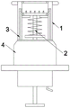
图1是本发明实施例一的主视结构示意图。Fig. 1 is a front view structural diagram of
图2是本发明实施例一的局部剖视结构示意图。Fig. 2 is a partial cross-sectional structural schematic diagram of
图3是本发明实施例一的剖视结构示意图。Fig. 3 is a schematic cross-sectional structure diagram of
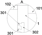
图4是本发明图3的A处放大结构示意图。FIG. 4 is a schematic diagram of the enlarged structure at A in FIG. 3 of the present invention.
图5是本发明图3的B处放大结构示意图。FIG. 5 is a schematic diagram of the enlarged structure at B in FIG. 3 of the present invention.
图6是本发明图3的C处放大结构示意图。FIG. 6 is a schematic diagram of an enlarged structure at point C in FIG. 3 of the present invention.
图7是本发明图3使用时的结构示意图。Fig. 7 is a schematic structural diagram of the present invention when Fig. 3 is used.
图8是本发明图7的D处放大结构示意图。FIG. 8 is a schematic diagram of an enlarged structure at D in FIG. 7 of the present invention.
图9是本发明实施例二的结构示意图(该图示出了与图3剖视截面在周向上错开30°的剖视图)。Fig. 9 is a schematic structural view of
图中,部件名称与附图编号的对应关系为:In the figure, the corresponding relationship between component names and drawing numbers is:
1、筒体;111、第一常规段;112、第二常规段;12、通气段;13、吸附通道;100、吸附腔室;101、阴部撑开圈;102、限位环A;103、限位环B;104、引流管;105、螺纹;;2、破膜机构;21吸附活塞;22套管;23旋柄;201、刀头座;20101、混合孔;202、刀头;203、推杆;204、挡环;205、弹性件;3、引流结构;301、头孔;302、连接孔;303、尾孔;4、挡座;5、柔性层。1. Cylinder body; 111. First conventional section; 112. Second conventional section; 12. Ventilation section; 13. Adsorption channel; 100. Adsorption chamber; , limit ring B; 104, drainage tube; 105, thread; 2, membrane breaking mechanism; 21 adsorption piston; 203, push rod; 204, stop ring; 205, elastic member; 3, drainage structure; 301, head hole; 302, connection hole; 303, tail hole; 4, stop seat; 5, flexible layer.
具体实施方式detailed description
下面结合附图和实施例对本发明的实施方式作进一步详细描述。以下实施例用于说明本发明,但不能用来限制本发明的范围。Embodiments of the present invention will be further described in detail below in conjunction with the accompanying drawings and examples. The following examples are used to illustrate the present invention, but should not be used to limit the scope of the present invention.
在本发明的描述中,除非另有说明,“多个”的含义是两个或两个以上;术语“上”、“下”、“左”、“右”、“内”、“外”、“前端”、“后端”、“头部”、“尾部”等指示的方位或位置关系为基于附图所示的方位或位置关系,仅是为了便于描述本发明和简化描述,而不是指示或暗示所指的装置或元件必须具有特定的方位、以特定的方位构造和操作,因此不能理解为对本发明的限制。此外,术语“第一”、“第二”、“第三”等仅用于描述目的,而不能理解为指示或暗示相对重要性。In the description of the present invention, unless otherwise stated, the meaning of "plurality" is two or more; the terms "upper", "lower", "left", "right", "inner", "outer" , "front end", "rear end", "head", "tail", etc. indicate the orientation or positional relationship based on the orientation or positional relationship shown in the drawings, and are only for the convenience of describing the present invention and simplifying the description, rather than Nothing indicating or implying that a referenced device or element must have a particular orientation, be constructed, and operate in a particular orientation should therefore not be construed as limiting the invention. In addition, the terms "first", "second", "third", etc. are used for descriptive purposes only and should not be construed as indicating or implying relative importance.
在本发明的描述中,需要说明的是,除非另有明确的规定和限定,术语“相连”、“连接”应做广义理解,例如,可以是固定连接,也可以是可拆卸连接,或一体地连接;可以是机械连接,也可以是电连接;可以是直接相连,也可以通过中间媒介间接相连。对于本领域的普通技术人员而言,可以具体情况理解上述术语在本发明中的具体含义。In the description of the present invention, it should be noted that unless otherwise specified and limited, the terms "connected" and "connected" should be understood in a broad sense, for example, it can be a fixed connection, a detachable connection, or an integral Ground connection; it can be mechanical connection or electrical connection; it can be direct connection or indirect connection through an intermediary. Those of ordinary skill in the art can understand the specific meanings of the above terms in the present invention in specific situations.
实施例一:Embodiment one:
如附图1至附图8所示:As shown in accompanying
本发明提供一种适用于妇产科的羊膜破膜器,包括筒体1和破膜机构2,筒体1内滑动连接有破膜机构2,且筒体1内设置有引流结构3,并且筒体1上还设置有挡座4;参考如图7和图8,筒体1的前端(即插入端)的外周壁上套接有一个阴部撑开圈101,且筒体1前端(即插入端)内周壁上设有一个限位环A102,并且当刀头座201与限位环A102底端面接触时刀头202露出预设长度,该预设长度为0.15-0.25cm,例如0.2cm,从而可防止刀头202露出过长导致割伤婴儿;参考如图3和图5,刀头座201包括混合孔20101,刀头座201上呈环形阵列状开设有贯通的混合孔20101,且混合孔20101为锥形孔状结构,并且当上下推动推杆203时混合孔20101处呈涡流状,从而通过混合孔20101处形成的涡流可头孔301处堵塞物的冲击式清理。The present invention provides an amniotic membrane breaker suitable for obstetrics and gynecology, comprising a
参考如图3,筒体1还设有限位环B103,筒体1内壁熔接有一个限位环B103;破膜机构2包括刀头座201、刀头202、推杆203、挡环204和弹性件205,刀头座201为圆柱形结构,且刀头座201可滑动连接在筒体1内,并且刀头座201上呈环形阵列状安装有刀头202;推杆203熔接在刀头座201底端面,即推杆203与刀头202相对设于刀头座201的相对两个面上,且推杆203上熔接有挡环204,挡环204相对刀头座201位于限位环B103的另一侧,并且推杆203外壁套接有一个弹性件205,弹性件205具体可为柱状弹簧;弹性件205头端与限位环B103底端面接触,且弹性件205尾端与挡环204顶端面接触,并且弹性件205组成了刀头座201和刀头202的弹性复位结构,从而在非使用状态下刀头座201和刀头202呈隐藏状态,从而避免本破膜器不慎掉落导致刀头202受损。推杆203上与还设有手柄,手柄位于筒体1的外部,并且手柄与刀头座201相对设于推杆203的杆体的两端。参考如图3,引流结构3包括多组引流通道,每组引流通道包括头孔301、连接孔302和尾孔303,头孔301、连接孔302和尾孔303依次连通,且且多个引流通道成环形陈列开设于于筒体1的壁上。Referring to Figure 3,
参考如图3和图4,引流通道共设有两处,且每处引流通道均包括头孔301;两个所述头孔301均与对应的连接孔302相连通,且四个头孔301共同组成了排液防堵塞结构,从而相比较单一头孔301来说防堵塞能力更强。头孔301靠近限位环A102设置,位于限位环B103与限位环A102,且与限位环B103与限位环A102两者之间的腔室连通,头孔3用于将羊水等导入引流通道,连接孔302与筒体1的轴线平行设置,尾孔303穿出筒体1,用于将引入的羊水等液体外排。Referring to Figure 3 and Figure 4, there are two drainage channels, and each drainage channel includes a
当刀头座201外拉抵接于限位环B103上时,头孔301露出打开,头孔301连通刀头座201与限位环A102之间的腔室。When the
参考如图3和图4,头孔301和尾孔303均呈倾斜状设置于筒体1上,且倾斜角度为60度,从而提高了液体在引流结构3内流通的顺畅性,进而进一步提高了引流结构3排液时的防堵塞能力。Referring to Fig. 3 and Fig. 4, the
参考如图3,筒体1还包括引流管104和螺纹105,筒体1开设有螺纹105,且筒体1后端外壁上还熔接有一根与筒体1内腔连通的引流管104,并且引流管104组成了辅助引流结构。Referring to Figure 3, the
参考如图3和图6,挡座4内壁开设有螺纹槽,且挡座4与螺纹105螺纹式连接,并且挡座4组成了筒体1的插入深度可调式限位结构,从而实现了插入深度的限位,防止工作中失误导致插入深度过大造成组织损伤。Referring to Fig. 3 and Fig. 6, the inner wall of the retaining
参考如图3,挡座4头端经倒角处理,且挡座4为阶梯座状结构;挡座4的高度大于螺纹105的高度,且挡座4组成了螺纹105的防护结构,从而避免了螺纹105与子宫内壁接触造成舒适度降低,且头端经倒角处理的挡座4在插入时更加顺滑。Referring to Fig. 3, the head end of the retaining
本实施例的具体使用方式与作用:The specific usage and function of this embodiment:
使用时,将筒体1从阴部插入,而后转动破膜机构2实现破膜;When in use, the
在使用过程中,第一,筒体1前端(即插入端)外周壁套接有一个阴部撑开圈101,且筒体1前端(即插入端)内周壁熔接有一个限位环A102,并且当刀头座201与限位环A102底端面接触时刀头202露出长度为0.15-0.25cm,例如0.2cm,从而可防止刀头202露出过长导致割伤婴儿;第二,因刀头座201为圆柱形结构,且刀头座201滑动连接在筒体1内,并且刀头座201上呈环形阵列状安装有刀头202;推杆203熔接在刀头座201底端面,且推杆203上熔接有挡环204,挡环204相对刀头座201位于限位环B103的另一侧,并且推杆203外壁套接有一个弹性件205,弹性件205具体可为圆柱形弹簧;弹性件205头端与限位环B103底端面接触,且弹性件205尾端与挡环204顶端面接触,并且弹性件205组成了刀头座201和刀头202的弹性复位结构,从而在非使用状态下刀头座201和刀头202呈隐藏状态,从而避免该破膜器不慎掉落导致刀头202受损;第三,因头孔301与筒体1前端内腔相连通,且共设置有两组,且两组头孔301均与连接孔302相连通,且两组头孔301共同组成了排液防堵塞结构,从而相比较头孔301来说防堵塞能力更强;第四,因头孔301和尾孔303均呈倾斜状铺设在筒体1上,且倾斜角度为60度,从而提高了液体在引流结构3内流通的顺畅性,进而进一步提高了引流结构3排液时的防堵塞能力;第五,因刀头座201上呈环形阵列状开设有混合孔20101,且混合孔20101为锥形孔状结构,混合孔20101的小端朝向刀头座201设有刀头202的面上,大端朝向刀头座201远离刀头202的面上,并且当上下推动推杆203时混合孔20101处呈涡流状,从而通过混合孔20101处形成的涡流可对头孔301处堵塞物的冲击式清理;第六,因挡座4为管状座结构,且挡座4内壁开设有螺纹槽,且挡座4与螺纹105螺纹式连接,并且挡座4组成了筒体1的插入深度可调式限位结构,从而实现了插入深度的限位,防止工作中失误导致插入深度过大造成组织损伤;第七,因挡座4的高度大于螺纹105的高度,且挡座4组成了螺纹105的防护结构,从而避免了螺纹105与子宫内壁接触造成舒适度降低,且头端经倒角处理的挡座4在插入时更加顺滑。During use, first, a genital expansion ring 101 is sleeved on the outer peripheral wall of the front end (ie, the insertion end) of the cylinder body 1, and a limit ring A102 is welded to the inner peripheral wall of the front end (ie, the insertion end) of the cylinder body 1, and When the cutter head 201 is in contact with the bottom end surface of the stop ring A102, the exposed length of the cutter head 202 is 0.15-0.25cm, such as 0.2cm, so as to prevent the cutter head 202 from being exposed too long and causing the baby to be cut; 201 is a cylindrical structure, and the cutter head seat 201 is slidingly connected in the cylinder body 1, and the cutter head seat 201 is equipped with cutter heads 202 in an annular array; the push rod 203 is welded on the bottom end surface of the cutter head seat 201, and the push rod 203 is welded with a retaining ring 204, the retaining ring 204 is located on the other side of the limit ring B103 relative to the cutter head seat 201, and an elastic member 205 is sleeved on the outer wall of the push rod 203, and the elastic member 205 can be specifically a cylindrical spring; The head end of the part 205 is in contact with the bottom surface of the limit ring B103, and the tail end of the elastic part 205 is in contact with the top surface of the retaining ring 204, and the elastic part 205 forms the elastic return structure of the cutter head seat 201 and the cutter head 202, so that when not in use In this state, the cutter head seat 201 and the cutter head 202 are in a hidden state, so as to avoid the damage to the cutter head 202 caused by the accidental drop of the membrane breaker; There are two groups, and the two groups of head holes 301 are connected with the connection hole 302, and the two groups of head holes 301 together form a liquid drainage anti-clogging structure, so that the anti-blocking ability is stronger than that of the head holes 301; the fourth , because the head hole 301 and the tail hole 303 are laid on the cylinder body 1 in an inclined shape, and the inclination angle is 60 degrees, thereby improving the smoothness of liquid circulation in the drainage structure 3, and further improving the drainage of the drainage structure 3 Anti-clogging ability during; the 5th, be provided with mixing hole 20101 in circular array shape on the cutter head seat 201, and the mixing hole 20101 is a tapered hole-like structure, the small end of mixing hole 20101 is provided with knife toward cutter head seat 201 On the surface of the head 202, the big end faces the cutter head seat 201 away from the surface of the cutter head 202, and when the push rod 203 is pushed up and down, the mixing hole 20101 is in a vortex shape, so that the vortex formed at the mixing hole 20101 can be aligned with the head hole 301 The impact cleaning of blockages; Sixth, because the retaining seat 4 is a tubular seat structure, and the inner wall of the retaining seat 4 is provided with thread grooves, and the retaining seat 4 is threadedly connected with the thread 105, and the retaining seat 4 forms the cylinder body 1 The insertion depth adjustable limit structure realizes the limit of the insertion depth and prevents tissue damage caused by excessive insertion depth caused by mistakes in work; The protective structure of the thread 105 is formed, thereby avoiding the reduction of the comfort caused by the contact between the thread 105 and the inner wall of the uterus, and the stopper 4 whose head end is chamfered is more smooth when inserted.
实施例二:Embodiment two:
该实施例中,与实施例1所不同的是:In this embodiment, the difference from
如图9所示,该图示出了与图3剖视截面在周向上错开30°的剖视图,筒体1的内腔包括常规段和通气段12,通气段的直径大于筒体1常规段的直径,通气段将常规段分隔成两段,两段分别为第一常规段111和第二常规段112,其中,第一常规段111位于该破膜器的前端,即插入端部分,限位环A102和限位环B103位于第一常规段111内。As shown in Figure 9, which shows a cross-sectional view staggered by 30° in the circumferential direction from the cross-sectional section in Figure 3, the inner chamber of the
通气段12靠近限位环B103设置,并位于限位环B103远离限位环A102的一侧,即限位环A102和通气段12相对位于限位环B103两侧,挡环204能够在第二常规段112和通气段内滑动,挡环204的尺寸相对实施例一中的更大,其直径大小与常规段(具体为第二常规段)相配匹,挡环204能够相对第二常规段112(具体为第二常规段)滑动,并且挡环204能够实现与常规段的滑动密封,从而使得挡环204起到密封活塞的作用。当挡环204在通气段内滑动时,挡环204的外周壁与通气段的壁之间形成环形的通气间隙,头孔301与第一常规段连通。
进一步地,挡环204远离该破膜器插入端一侧的外周圈上设有导气部,导气部呈倒角状,导气部用于挡环204快速滑动到通气段内,实现第二常规段112与外部的气体导通。Further, an air guide part is provided on the outer circumference of the retaining
引流通道头孔301沿着筒体1轴线方向的宽度大于刀头座201的厚度。如此,在刀头座201移动的过程中,使得外部与通气段之间能够通过引流通道实现气体流通,实现压力补偿,从而使得推杆在手术时能够顺利动作。The width of the drainage
该实施例中的混合孔20101还具有限流作用,具体参看后续的使用方法描述。The mixing
破膜机构2还包括吸附活塞21,吸附活塞21可滑动套接于推杆203上,吸附活塞21与挡环204彼此平行且间隔预设距离设置,吸附活塞21位于挡环204和推杆23的手柄之间,吸附活塞21远离挡环204的端面上连接有套管22,套管22的第一端与挡环204固定连接,第二端伸出筒体1,并旋拧于筒体1上,即螺纹连接于筒体1上,套管22的第二端端头上设有旋柄23,旋柄23外露出筒体1,并且旋柄23相对手柄更加靠近筒体1设置,吸附活塞21朝向挡环204的端面上设有密封圈,密封圈套设于推杆203上,用于实现吸附活塞21与推杆203之间的滑动密封。The
当刀头座201抵接于限位环B103上时,吸附活塞、挡环204以及筒体1之间围设形成吸附腔室100,筒体1的壁上开设有吸附通道13,吸附通道13共开设有四条,并且四条吸附通道13沿着筒体1的周向均匀分布,相邻的两条吸附通道13之间彼此间隔60°,吸附通道13连通外部与吸附腔室100,吸附通道13的一端开设于筒体1插入端的端面上,另一端开设于筒体1第二常规段112的内壁上,具体开设于吸附腔室100对应的筒体1的内壁上,如此,实现了筒体1插入端与吸附腔室100之间的连通。When the
进一步地,筒体1前端,即插入端的端面上还设有柔性层5,柔性层5具体可为医用橡胶材料制成,柔性层用于羊膜的柔性接触,并实现密封吸附作用。并且,柔性层对应吸附通道的位置开设有开孔,开孔用于与吸附通道连通。该实施例中,为了刀头202能够顺利伸出柔性层,相对实施例一中的刀头202作了适应性增长。Further, a
对于该实施例中的破膜器的其他部分结构的描述,可参见实施例一,此处不再一一赘述。For the description of other partial structures of the membrane rupturer in this embodiment, reference may be made to
使用方法:Instructions:
本实施例中的破膜器使用时,可参考如下步骤:When using the membrane breaker in this embodiment, refer to the following steps:
1、首先在弹性件205推杆外拉抵接于限位环B103上,此时挡环204位于第二常规段112内,首先将该破膜器的插入端插入阴部,并使得柔性层5紧贴于羊膜上,然后通过外旋旋柄使得吸附活塞外旋,吸附腔室的空间增大,即吸附活塞与限位环B103的距离增大,使得吸附腔室的真空度增大,从而使得羊膜通过吸附通道吸附在柔性层上;1. First, the push rod of the
2、外拉筒体1,使得羊膜与婴儿产生一定的隔离距离;2. Pull the
3、通过推杆快速前推挡环204,使得挡环204在惯性力作用下自第二常规段进入通气段,此时挡环204的外周壁与通气段的壁之间形成通气间隙,此过程中,刀头座201与羊膜之间的气体分成两路,一路通过引流通道外排,此为主要排气路径,另一路通过混合孔20101进入通气段内,再自通气间隙进入挡环204和吸附活塞之间的真空区内,由于混合孔20101具有限流作用,此一路的流量较小,仅仅起到压力补偿的作用,以方便刀头座201继续前推,并不影响对羊膜的吸附;3. Push the retaining
4、当刀头座201快速前推至超过头孔301,并快速撞击羊膜,在对羊膜的吸附力未解除前,刀头座201上的刀头202将羊膜破裂。4. When the
该实施例中,破膜器合理的结构设计,使得羊膜能够被吸附外拉并与羊膜内的婴儿间隔一定距离,一方面由于破膜时羊膜被吸附撑紧,刀头202能够较为容易准确的将羊膜破裂,破膜准确度和效率均大大提高,另一方面由于破膜时羊膜与羊膜内的婴儿间隔一定距离,能够进一步防止婴儿被刺伤,大大提高了手术的安全性。In this embodiment, the reasonable structural design of the amniotic membrane device enables the amniotic membrane to be absorbed and pulled out and kept at a certain distance from the baby in the amniotic membrane. Rupturing the amniotic membrane greatly improves the accuracy and efficiency of membrane rupture. On the other hand, when the amniotic membrane is ruptured, there is a certain distance between the amniotic membrane and the baby in the amniotic membrane, which can further prevent the baby from being stabbed and greatly improve the safety of the operation.
本发明的实施例是为了示例和描述起见而给出的,而并不是无遗漏的或者将本发明限于所公开的形式。很多修改和变化对于本领域的普通技术人员而言是显而易见的。选择和描述实施例是为了更好说明本发明的原理和实际应用,并且使本领域的普通技术人员能够理解本发明从而设计适于特定用途的带有各种修改的各种实施例。The embodiments of the present invention have been presented for purposes of illustration and description, but are not intended to be exhaustive or to limit the invention to the form disclosed. Many modifications and changes will be apparent to those of ordinary skill in the art. The embodiment was chosen and described in order to better explain the principles of the invention and the practical application, and to enable others of ordinary skill in the art to understand the invention and design various embodiments with various modifications as are suited to the particular use.
Claims (7)
Priority Applications (1)
| Application Number | Priority Date | Filing Date | Title |
|---|---|---|---|
| CN202110840571.6A CN113520552B (en) | 2021-07-24 | 2021-07-24 | Amnion membrane rupture device suitable for gynaecology and obstetrics |
Applications Claiming Priority (1)
| Application Number | Priority Date | Filing Date | Title |
|---|---|---|---|
| CN202110840571.6A CN113520552B (en) | 2021-07-24 | 2021-07-24 | Amnion membrane rupture device suitable for gynaecology and obstetrics |
Publications (2)
| Publication Number | Publication Date |
|---|---|
| CN113520552A CN113520552A (en) | 2021-10-22 |
| CN113520552B true CN113520552B (en) | 2022-12-27 |
Family
ID=78120750
Family Applications (1)
| Application Number | Title | Priority Date | Filing Date |
|---|---|---|---|
| CN202110840571.6A Active CN113520552B (en) | 2021-07-24 | 2021-07-24 | Amnion membrane rupture device suitable for gynaecology and obstetrics |
Country Status (1)
| Country | Link |
|---|---|
| CN (1) | CN113520552B (en) |
Citations (4)
| Publication number | Priority date | Publication date | Assignee | Title |
|---|---|---|---|---|
| US5395379A (en) * | 1993-07-22 | 1995-03-07 | Deutchman; Mark E. | Extractor for childbirth and aspirator/injector device |
| CN106974710A (en) * | 2017-04-27 | 2017-07-25 | 黄士玉 | A kind of gynemetrics's film breaking unit and its application method |
| CN107456261A (en) * | 2017-06-15 | 2017-12-12 | 青岛江河湖海创新技术研究院有限公司 | A kind of obstetrics and gynecology department membrane-repturing device |
| CN213129810U (en) * | 2020-05-12 | 2021-05-07 | 张洪梅 | Membrane rupture device convenient to operate for obstetrics and gynecology department |
Family Cites Families (8)
| Publication number | Priority date | Publication date | Assignee | Title |
|---|---|---|---|---|
| CN203017048U (en) * | 2012-12-20 | 2013-06-26 | 刘艳丽 | Membrane rupturing needle specific for puerpera |
| CN206239487U (en) * | 2016-08-02 | 2017-06-13 | 张保霞 | A kind of gynemetrics's amnion broken instrument |
| CN208002869U (en) * | 2017-12-02 | 2018-10-26 | 陈萍 | Cardiological clinic drains puncture outfit |
| CN108451609B (en) * | 2018-03-14 | 2021-01-15 | 德州市人民医院 | Obstetrical amniotic membrane rupture device with cleaning function |
| CN109259831A (en) * | 2018-09-21 | 2019-01-25 | 王书君 | A kind of amniotic fluid rupture of membranes drainage device of obstetrics and gynecology department anti-overflow |
| CN209884282U (en) * | 2018-11-21 | 2020-01-03 | 朱燕 | Amniotic fluid membrane rupturing device for obstetrics and gynecology department |
| CN209789973U (en) * | 2019-02-25 | 2019-12-17 | 孙芬 | Laparoscope puncture outfit |
| CN213129802U (en) * | 2020-07-29 | 2021-05-07 | 罗洁 | Puncture needle for nephrology department |
-
2021
- 2021-07-24 CN CN202110840571.6A patent/CN113520552B/en active Active
Patent Citations (4)
| Publication number | Priority date | Publication date | Assignee | Title |
|---|---|---|---|---|
| US5395379A (en) * | 1993-07-22 | 1995-03-07 | Deutchman; Mark E. | Extractor for childbirth and aspirator/injector device |
| CN106974710A (en) * | 2017-04-27 | 2017-07-25 | 黄士玉 | A kind of gynemetrics's film breaking unit and its application method |
| CN107456261A (en) * | 2017-06-15 | 2017-12-12 | 青岛江河湖海创新技术研究院有限公司 | A kind of obstetrics and gynecology department membrane-repturing device |
| CN213129810U (en) * | 2020-05-12 | 2021-05-07 | 张洪梅 | Membrane rupture device convenient to operate for obstetrics and gynecology department |
Also Published As
| Publication number | Publication date |
|---|---|
| CN113520552A (en) | 2021-10-22 |
Similar Documents
| Publication | Publication Date | Title |
|---|---|---|
| US6228058B1 (en) | Sleeve trocar with penetration indicator | |
| US5718676A (en) | Grooved phaco-emulsification needle | |
| US3765417A (en) | Arcuate tampon applicator | |
| CN113520552B (en) | Amnion membrane rupture device suitable for gynaecology and obstetrics | |
| CN108883258B (en) | Medical device for delivering a plug to a void | |
| CN106974710B (en) | A kind of gynemetrics's film breaking unit | |
| CN108451609A (en) | Obstetrics' amnion broken instrument with cleaning function | |
| CN205597978U (en) | Ultrasonic knife sleeve pipe aspirator and ultrasonic knife | |
| CN208065232U (en) | Built-in multi-channel type handle energy converter and ultrasonic surgical apparatus | |
| CN215606151U (en) | Water plugging structure of intravaginal hysteroscope | |
| CN213283210U (en) | Thrombus suction device for vascular surgery | |
| CN214402787U (en) | A grouting check device and grouting machine | |
| CN103622830B (en) | There is the postoperative suction hose of anti-function of choking | |
| CN213552142U (en) | Suction structure for embolectomy | |
| CN209951910U (en) | A quantitative spray type debridement applicator | |
| CN121512632A (en) | A medical ultrasonic scalpel with a built-in internal suction device | |
| CN216394860U (en) | Drainage tube device based on puncture and indwelling | |
| CN107693092A (en) | A kind of portable disposable uterine cavity tissue sucker | |
| CN207886236U (en) | A kind of haemorrhoids ligation apparatus | |
| CN219126570U (en) | Tissue removal instrument | |
| CN217828025U (en) | A uterine rotary cutter for gynecological surgery | |
| CN219397506U (en) | Cervical mucus suction device | |
| CN206463339U (en) | A kind of novel nasal cavity inbalation administration device | |
| CN206304161U (en) | The attractor of device for endoscopic thyroid surgery | |
| CN219764067U (en) | Airflow control part and handheld suction device |
Legal Events
| Date | Code | Title | Description |
|---|---|---|---|
| PB01 | Publication | ||
| PB01 | Publication | ||
| SE01 | Entry into force of request for substantive examination | ||
| SE01 | Entry into force of request for substantive examination | ||
| TA01 | Transfer of patent application right |
Effective date of registration: 20221206 Address after: 362018 Comprehensive Building of Quanzhou Bozhi Cultural Goods Co., Ltd., No. 252, Yunlu Road, Donghai Street, Fengze District, Quanzhou, Fujian Applicant after: Quanzhou Maker Maternity Hospital Co.,Ltd. Address before: 276800 Antai Crystal Garden, Donggang District, Rizhao City, Shandong Province Applicant before: Fan Kailing |
|
| TA01 | Transfer of patent application right | ||
| GR01 | Patent grant | ||
| GR01 | Patent grant | ||
| PE01 | Entry into force of the registration of the contract for pledge of patent right |
Denomination of invention: A type of amniocentesis device suitable for obstetrics and gynecology Granted publication date: 20221227 Pledgee: Fujian Straits bank Limited by Share Ltd. Quanzhou branch Pledgor: Quanzhou Maker Maternity Hospital Co.,Ltd. Registration number: Y2024980056850 |
|
| PE01 | Entry into force of the registration of the contract for pledge of patent right |