CN1135155C - Razor blade assembly - Google Patents
Razor blade assembly Download PDFInfo
- Publication number
- CN1135155C CN1135155C CNB971937672A CN97193767A CN1135155C CN 1135155 C CN1135155 C CN 1135155C CN B971937672 A CNB971937672 A CN B971937672A CN 97193767 A CN97193767 A CN 97193767A CN 1135155 C CN1135155 C CN 1135155C
- Authority
- CN
- China
- Prior art keywords
- blade assembly
- pivot
- razor blade
- housing
- protective cover
- Prior art date
- Legal status (The legal status is an assumption and is not a legal conclusion. Google has not performed a legal analysis and makes no representation as to the accuracy of the status listed.)
- Expired - Lifetime
Links
- 230000001681 protective effect Effects 0.000 claims description 50
- 230000000284 resting effect Effects 0.000 claims description 21
- 238000009434 installation Methods 0.000 claims description 3
- 230000000630 rising effect Effects 0.000 claims description 2
- 230000007423 decrease Effects 0.000 claims 1
- 230000000694 effects Effects 0.000 description 4
- 230000003068 static effect Effects 0.000 description 4
- 239000004033 plastic Substances 0.000 description 3
- 229920003023 plastic Polymers 0.000 description 3
- 238000005452 bending Methods 0.000 description 2
- 239000002184 metal Substances 0.000 description 2
- 241000220317 Rosa Species 0.000 description 1
- 230000000712 assembly Effects 0.000 description 1
- 238000000429 assembly Methods 0.000 description 1
- 238000006073 displacement reaction Methods 0.000 description 1
- 239000013536 elastomeric material Substances 0.000 description 1
- 230000001815 facial effect Effects 0.000 description 1
- 230000002349 favourable effect Effects 0.000 description 1
- 230000036541 health Effects 0.000 description 1
- 238000012856 packing Methods 0.000 description 1
- 239000002985 plastic film Substances 0.000 description 1
- 230000035807 sensation Effects 0.000 description 1
- 229920002725 thermoplastic elastomer Polymers 0.000 description 1
Images


Classifications
-
- B—PERFORMING OPERATIONS; TRANSPORTING
- B26—HAND CUTTING TOOLS; CUTTING; SEVERING
- B26B—HAND-HELD CUTTING TOOLS NOT OTHERWISE PROVIDED FOR
- B26B21/00—Razors of the open or knife type; Safety razors or other shaving implements of the planing type; Hair-trimming devices involving a razor-blade; Equipment therefor
- B26B21/08—Razors of the open or knife type; Safety razors or other shaving implements of the planing type; Hair-trimming devices involving a razor-blade; Equipment therefor involving changeable blades
- B26B21/14—Safety razors with one or more blades arranged transversely to the handle
- B26B21/22—Safety razors with one or more blades arranged transversely to the handle involving several blades to be used simultaneously
-
- B—PERFORMING OPERATIONS; TRANSPORTING
- B26—HAND CUTTING TOOLS; CUTTING; SEVERING
- B26B—HAND-HELD CUTTING TOOLS NOT OTHERWISE PROVIDED FOR
- B26B21/00—Razors of the open or knife type; Safety razors or other shaving implements of the planing type; Hair-trimming devices involving a razor-blade; Equipment therefor
- B26B21/40—Details or accessories
- B26B21/4012—Housing details, e.g. for cartridges
-
- B—PERFORMING OPERATIONS; TRANSPORTING
- B26—HAND CUTTING TOOLS; CUTTING; SEVERING
- B26B—HAND-HELD CUTTING TOOLS NOT OTHERWISE PROVIDED FOR
- B26B21/00—Razors of the open or knife type; Safety razors or other shaving implements of the planing type; Hair-trimming devices involving a razor-blade; Equipment therefor
- B26B21/08—Razors of the open or knife type; Safety razors or other shaving implements of the planing type; Hair-trimming devices involving a razor-blade; Equipment therefor involving changeable blades
- B26B21/14—Safety razors with one or more blades arranged transversely to the handle
- B26B21/22—Safety razors with one or more blades arranged transversely to the handle involving several blades to be used simultaneously
- B26B21/222—Safety razors with one or more blades arranged transversely to the handle involving several blades to be used simultaneously with the blades moulded into, or attached to, a changeable unit
- B26B21/225—Safety razors with one or more blades arranged transversely to the handle involving several blades to be used simultaneously with the blades moulded into, or attached to, a changeable unit the changeable unit being resiliently mounted on the handle
-
- B—PERFORMING OPERATIONS; TRANSPORTING
- B26—HAND CUTTING TOOLS; CUTTING; SEVERING
- B26B—HAND-HELD CUTTING TOOLS NOT OTHERWISE PROVIDED FOR
- B26B21/00—Razors of the open or knife type; Safety razors or other shaving implements of the planing type; Hair-trimming devices involving a razor-blade; Equipment therefor
- B26B21/40—Details or accessories
- B26B21/4012—Housing details, e.g. for cartridges
- B26B21/4031—Housing details, e.g. for cartridges characterised by special geometric shaving parameters, e.g. blade span or exposure
Abstract
A razor blade assembly (10) for mounting on a handle via a pivotal connection, the assembly including a housing (12) that carries three blade members (18, 20, 22), each having leading edges (29), and has a guard portion (14), a cap structure (2), and arcuate bearing surfaces (42, 44) below the blade carrying portion that pivotally engage shell bearing connections of the handle. The pivot axis of the razor blade assembly is located in a region defined by an imaginary boundary extending from the first leading edge to the second leading edge when both are in the unloaded position, extending upward and rearward from the second leading edge to a position slightly above the upper surface of the housing at a location in front of the third leading edge, extending along and slightly above the upper surface of the housing to a position in front of the first leading edge, extending downward and forward to a location within the guard portion (14) below and forward of the first leading edge, and extending from the location within the guard portion upward and rearward to the first leading edge. The pivot axis is advantageously located at the secondary blade member leading edge. In preferred embodiments the blade members are resiliently mounted, and at least two of the blade member leading edges have sharpened cutting edges. The housing is provided with a cam surface (54) engaged by a spring loaded cam follower (70) on the razor handle (72), and the cam can be contoured to provide an at-rest position other than a position midway between the limit of forward and rearward arcuate travel.
Description
The present invention relates to by the pivotally connected razor blade assembly of using on the handle that is installed to.
A kind of well-known razor blade assembly; for example; resemble in U.S. Pat 4573266 and US 4586255 indicated; it has used a kind of spring-loaded protective cover member at the place, front of this device; and used a lubricated bar shaped cover at its place, back, reach and between them, used two spring-loaded blade members.U.S. Pat 5249361 illustrates the fixedly blade apparatus of protective cover of a kind of similar band.The device of these two kinds of patterns all has guide rail and circular surface, is used for forming pivotally connected with the cartridge housing on the razor handle.Cam face on spring-loaded cam-follower on each razor handle and the blade apparatus bottom interacts, so that with respect to handle each device is biased into the centre position.During shaving, this device can from respect to the centre position of handle forward (clockwise) or backward (inhour) rotate around pivot, and each blade can move in housing with respect to skin surface, so that follow the profile of skin surface during shaving.In the commodity embodiment of these razor blade assemblies, (sell with Sensor and Sensor Excel trade mark) from The Gillette Company, each cartridge housing provide around one between the blade of two elastic movements and above axis rotation (their unloaded state is regarded as with reference to state).Especially, each pivot is positioned at the centre of slit, is provided with first (top) insert supporting member and at the place, top of a clip each blade members is remained on the tool holder casing in this slit.Therefore, providing pivot above each blade cut sword with above the housing.This pivot thereby can think during a face shaves, to be arranged in " face " (that is to say, above each engages the member of skin).Each razor blade assembly is discarded after repeatedly shaving, and uses with the handle that cartridge housing and spring-loaded cam-follower are housed with the razor blade assembly of replacing.Identical razor handle can use together with the razor blade assembly of two kinds of forms because they the two have the track and the circular surface of same size.
Hope improves the performance that shaves by three blades are set in a knife rest.Yet; in a kind of common double blade tool holder casing of widening of protective cover that supports engagement skin and cap surface; hold one the 3rd blade simply and can cause when this knife rest rotates along with shaving force, the cartridge housing of handle and the interference of a kind of geometry between the tool holder casing.
In one case, characteristics of the present invention are a kind of being used for pivotally connectedly to be installed in a razor blade assembly on the handle by one substantially.This razor blade assembly comprises a housing, and this housing is installed three blade members, and each blade members all has a front edge, and this razor blade assembly has: a protective cover part of locating in front; A lid structure of locating in the back; A blade members mounting portion between this protective cover part and lid structure, at the top surface of each side edge of this blade members mounting portion; and the arc shaft bearing surface below this blade members mounting portion, the be connected with a joggle surface of each pivot of handle arrangement of this blade members mounting portion slidingtype.These curved surfaces all have such radius of curvature; so that on handle, provide pivotal mounting around a pivot; this pivot is arranged in the zone that the border by an imagination limits; the border of this imagination is that the two all is in the unloaded state (resting position that this state is equivalent to rise when first and second blade members; the blade members that adopts elasticity to install simultaneously) time; extend to the front edge of second blade members from the front edge of first blade members; from this second front edge upwards and extend rearward to slightly above the position forward housing upper surface of the 3rd blade members front edge; also extend to a position of the first front edge front slightly above it along the upper surface of housing; extend to a place in the protective cover part in the below of this first blade members front edge and the place ahead downwards and forward, and the place in the protective cover part upwards and extend rearward to first front edge.So this pivot of location can adapt to three blade members, and still keeps the good characteristics that shave.
In some preferred embodiments, the lid structure has a smooth aid that shaves, this aid that shaves is contained in the cavity that housing locates later, and this pivot is positioned at (preferably near the front edge of intermediate blades member) on the skin surface during shaving, so that this blade apparatus can be desirable up to about 45 ° mobile radian by one of the segmental bearing surface rotation of engagement razor handle upper bearing (metal) shell, and do not have cartridge housing to fall into this housing, the interference in the aid zone of especially having avoided shaving.Housing has some clips in its each end, and they remain on each blade members on the housing.At least two blade members have front edge, and these front edges are the sharp cutting edges of mill.Each blade members has the blade cut sword member that is installed on a L shaped base and the platform member.Each blade members is installed in the housing, is used for elastic movement during shaving.There is a constant radius of curvature on this segmental bearing surface.The protective cover member has some upwardly extending ribs, and these ribs have tip, and the latter is positioned at the top on a plane passing each front edge.Each shaving force is by being balanced comparably above each cutting edge at place, plane this pivotal line of location, and two cutting edges are passed wherein and near the mid point between the surface of the engagement skin of lid and protective cover in this plane.
In another case, characteristics of the present invention are to be used to be installed in a razor blade assembly on the handle substantially, and this handle has a pivot joint structure and a spring-loaded cam-follower.This razor blade assembly comprises a housing, and this housing has: a protective cover part in front; Cover in the back; Blade members mounting portion between this protective cover part and cover; With a kind of structure, this structure cooperates with the handle pivot syndeton, so as housing through one forward the pivot stop position and the circular motion between the pivot stop position backward.This housing also has the cam surface on a band top, and this top is positioned, so that except providing one between the position in preceding pivot stop position and pivot stop position middle, back, also provide a resting position.This top can be positioned near the housing front, so that make this device can make progress (also being referred to as " forward ") be biased on the blade handle, thereby the arc lower surface of knife rest produces a pivot stop position forward, therefore lid at first contacts skin, each shaving force makes the knife rest orientation then, and the low initial angle of attack of blade is provided.In addition; this top can be positioned near the rear portion of housing; so that this device (also being referred to as " backward ") downwards is biased on the razor handle; thereby the arc lower surface of knife rest produces a pivot stop position backward; therefore provide the higher initial angle of attack of each blade, and protective cover at first contacts skin.This top also can be arranged on such place, and this place provides forward and pivot backward rotation, but on both direction the degree difference.
From the explanation of following preferred embodiment with from every claim, other advantage of the present invention and characteristics will be clearly.
Fig. 1 is the perspective view according to razor blade assembly of the present invention;
Fig. 2 is the rearview of the razor blade assembly of Fig. 1;
Fig. 3 is the vertical part sectioned view of getting in the place along 3-3 among Fig. 2 of the razor blade assembly of Fig. 1;
Fig. 4 is the vertical part sectioned view of getting in the place along 4-4 among Fig. 2 of the razor blade assembly of Fig. 1;
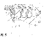
Fig. 5 is the vertical part sectioned view of getting in the place along 5-5 among Fig. 2 of another embodiment of the razor blade assembly of Fig. 1;
Fig. 6 is the vertical part sectioned view of getting in the place along 6-6 among Fig. 2 of another embodiment of the razor blade assembly of Fig. 1;
Fig. 7 is the vertical cross section of the razor blade assembly of Fig. 3, and the handle that wherein is shown in broken lines and the part of cam-follower thereof are positioned at resting position;
Fig. 8 is the razor blade assembly of Fig. 7 and the vertical cross section of handle, and razor blade assembly is positioned at pivoted position shown in it;
Fig. 9 is the vertical cross section of the razor blade assembly of Fig. 5, and the handle and the cam-follower thereof that wherein are shown in broken lines are positioned at resting position;
Figure 10 is the razor sword sheet device of Fig. 9 and the vertical cross section of handle, and razor blade assembly is positioned at pivoted position shown in it.
Referring to Fig. 1 to Fig. 3, these illustrate and are installed in a razor blade assembly 10 on the handle, and this handle has a pivot joint structure described in No. the 4573266th, United States Patent (USP).Razor blade assembly 10 comprises: plastic casing 12; The protective cover member of locating previously at housing 12 14; The lid member of locating later at housing 12 2 and be arranged on wherein lubricious strip female cap member 16 at place, housing 12 rear portions; And three blades 18,20 in protective cover member 14 and the lubricated blade mounting portion of covering the housing 12 between the member 16 and 22.First blade, 18 the most close protective covers, second blade 20 is the most close protective cover secondly, and the 3rd blade 22 is from protective cover farthest.Lid member 2 has a upper surface portion 3 and a rear surface part 4.Lid member 2 is equipped with an elongated cavity 5, and these cavity 5 parts are limited by upper surface portion 3 and rear surface part 4.Lubricated lid member 16 has the base 15 in the cavity of locating at housing 12 rear portions of packing into 5.Lubricated lid member 16 has a top surface 17 that is mixed in the rear surface 19, so that generally form the continuity of a kind of this lid member upper surface and rear surface part.Each all comprises a front edge mounting portion 23 that separates that is bearing on the L shaped member blade 18,20,22, and this L shaped member has a platform 25 and a base portion 27.Each front edge mounting portion 23 all has a corresponding front edge 29, and this front edge 29 is generally towards protective cover member 14.Each front edge 29 can form sharp cutting edge.Metal holder 24,26 each blade 18,20 of protection of two side edge of housing 12 and 22 end.Each blade members 18,20,22 can form and be fixed in the housing 12, but preferably they are that elasticity is installed, and (that is to say by the resting position that plastic sheet spring arm 28,30,32 is biased to the rise of shown in Figure 1 they, do not loaded) by shaving force, these sheet spring arms and plastic casing 12 become integral body, and extend from its both sides.
It is desirable to provide three blade members, so that by a fine adjustment largely is provided when determining to shave geometry, for example can set different blades and expose situation, or respectively organize the different span of setting between the two adjacent elements at contact skin, more tight ness rating is provided and controls the performance that shaves, as in PCT bulletin WO 95/09071, describing in detail, thereby merge disclosure here with reference to the geometry that is used to shave.Yet adding one the 3rd blade simply can increase resistance unfriendly, and this is recognized this is because due to cutting force is applied on the more blade.It is desirable to housing 12 even as big as not only holding three blade members, cover member 16 but also hold the protective cover 14 of above-mentioned band elastic fin 66 and lubricate, to reduce each resistance.
Referring to Fig. 2, extension 34,36 is positioned at the place, bottom of housing 12, and carries the opposed warp rail 38,40 that extends internally, and crooked track 38,40 has corresponding curved surface 42,44.The lower surface 46,48 of housing 12 is crooked equally, and and extension 34,36 pivot joint structure is provided together, this pivot joint structure cooperates with each element on the handle, as what in U.S. Pat 4488357, US 4498235, US 4492025, US 4573266, US 4586255 and US 4756082, described in detail, thereby, be used for disclosing the cartridge housing syndeton between a razor blade assembly and the handle with they merging references.
Referring to Fig. 2, Fig. 3 and Fig. 4, should see that the lower surface 46,48 of blade apparatus track 38,40 and housing 12 defines the arcuate slots 98,100 that is fit to hold razor handle cartridge housing (not shown) together.Referring to Fig. 4, the arcuate slots 98 of tangent is set between the lower surface 46 of bending and crooked track 38 shown in the figure, extend the center line 99 that prolongs therebetween.Each cartridge housing comprises a pivot mounting structure, and this pivot mounting structure is fit to match with above-mentioned blade apparatus pivot mounting structure, to make things convenient for the pivotally connected of blade apparatus and razor handle device.
Fit structure (not shown) on the handle cartridge housing has some stop surfaces, as what in Fig. 1 and 3, be clear that, they prevent that back extensional surface 39 from further moving up so that a pivot stop position forward to be provided, and prevent that front extensional surface 41 from further moving down so that a pivot stop position backward to be provided.As what in Fig. 2 and 3, be clear that, each cartridge housing (not shown) on the handle has some grooves, they cooperate with the stop surfaces 35,37 that forms on corresponding crooked lower surface 46,48, come additional pivot stop position backward further to move down preventing.
As indicated in Fig. 3 and 4, the top surface of track 38,40 and housing lower surface 46,48 all has the radius of curvature around pivot P, and this pivot is positioned at the cutting edge place of second blade 20.The curved surface 42,44 of extension 34,36 is equally around pivot P bending.It is 0.2291 inch (5.82mm) that the surface of the top curved of track 38,40 has radius of curvature, it uses the arrow that extends from pivot P to illustrate in Fig. 3, and lower surface 46,48 has radius of curvature is 0.1921 inch (4.88mm), it uses the arrow that extends from pivot P to illustrate in Fig. 4, and respective surfaces is measure-alike in their size and the commercially available Sensor board razor blade assembly that has earlier.Although the blade members mounting portion extends back to hold the 3rd blade members on width significantly in the past, adopt identical radius that razor blade assembly 10 and existing Sensor participants in a bridge game's handle are used together.A large amount of existing handles of this kind are bought by the consuming public.The blade members mounting portion of significantly widening results from the existence of additional blade members, and each blade members is positioned or mutual span of a blade or spacing are arranged herein, and this span or spacing are crucial to span on the common Sensor formula knife rest or spacing.Prepare three blade members each can differently be set the span between the adjacent blade members,, it is merged disclosure here with reference to the geometry that is used to shave as in PCT bulletin WO 95/09071, describing in detail.Concerning the blade of each elastic movement, common inter-blade span is between 0.5mm and 2.0mm, is typically to be about 1.5mm.The big blade members mounting portion of device 10 has the effect to the lubricated bar female cap member of pusher, so that easily it is contained on the knife rest, and make it can occupy one otherwise by the occupied zone of pivotally connected curved surfaces of existing double blade device, especially can disturb the cartridge housing of razor handle, if this knife rest turns over typical about 40 ° to the 50 ° arcs that allow rotation with a Sensor formula knife rest.When keeping lubricated bar female cap member with identical radius of curvature, be reduced to the cutting edge of intermediate blades by top with pivot each clip between two blades (as getting existing two blade structures of making object of reference), hold bigger blade members installation region, and still keep the highest radian that is about 45 ° of total rotation of allowing, and do not cause the interference of geometry.
Still referring to Fig. 3, cam surface 50 forms in the bottom of housing 12.This cam surface 50 has two measure-alike and inclined-plane and tops 52 that direction is opposite, and this top 52 is located at the position, middle between the front and back of cam surface 50.Cam surface 50 makes device 10 rotate same degree around pivot forward or backward during shaving, and is fit to hold a cam-follower, knife rest is biased in 40 ° of total rotations to the scope of 50 ° of radians.
Referring to Fig. 5, razor blade assembly 10 ' has a cam surface 54 with a top 56, and this top is positioned at its front end place, but others have and install 10 identical structures.Cam surface 54 is so formed profile, so that cam-follower 70 is compressed to when it follows that Fig. 3 embodiment is in resting position and compressed same degree during along the cam surface 50 of the postrotational stop position of the complete pivot of radian of rotation.Because this cam-follower is spring-loaded, so on the knife rest of the embodiment of Fig. 3 or Fig. 5, with complete postrotational position identical restoring force is arranged at their corresponding initial positions.
Referring to Fig. 7-10, Fig. 7 and 9 illustrates and is used for razor blade assembly 10,10 ' resting position, and Fig. 8 and 10 illustrates the postrotational position of respective pivot that they can produce during shaving.In static position or in complete postrotational position, the distance from cam surface 54 to cartridge housing is with identical from the distance of cam surface 50 beginnings.In static position, the distance of 54 overhead cam followers, 70 points of tangency is with identical to the distance of cam surface 50 overhead cam followers 70 points of tangency from pivot P to cam surface.In complete postrotational position, at the vertical range top offset with respect to the static position points of tangency, displacement is with identical with identical point place on the tangent cam surface 50 of cam-follower 70 at the cam surface 54 at the points of tangency place of cam-follower 70.
Concerning razor blade assembly 10 (Fig. 7), resting position is the centre position; In this position, a plane passing each cutting edge is perpendicular to the axis 74 of cam-follower 70 along its slip.When this resting position, 52 places rest in this follower from position that handle 72 at utmost extends to spring-loaded cam-follower 70 on the top.Device 10 can be from (" making progress ") or (" the downwards ") rotation backward forward of this resting position.
Fig. 8 illustrates the razor blade device 10 that (inhour among Fig. 6) pivot that makes progress is screwed into a forward facing position, and this position may mainly be caused by each the downward power on the protective cover 14 in the operating period of shaving.Pass the axis of reference 75 that constitutes perpendicular to the pivotal line of blade apparatus 10 and rotated a rotation radian measure alpha that is about 22.5 ° with respect to axis of reference 74 pivots.
Referring to Fig. 9, razor blade assembly 10 ' turns forward in its resting position (" to upper offset "), makes the spring-loaded cam-follower 70 that leans against on the top 56 be in cam-follower 70 from the position that handle 72 at utmost stretches out.Device 10 ' can only rotate to a position backward from this resting position downward (clockwise at Fig. 9), as shown in Figure 10, and (" making progress ") rotation forward.This orientation to upper offset presents the lower effective angle of attack of the junior one of each blade, so that the more initial comfortable and less possibility of shaving the bark skin is provided.
During shaving, each blade members 18,20,22 is with respect to housing 12 elasticity activity independently, and housing 12 rotates around pivot with respect to handle 12, so each cutting edge is easy to follow the profile of skin surface.All three blade members all have sharp cutting edge, so that at three local cutting healths or facial hair.In addition, each blade is set to has the different degree of exposing, expose degree as increasing gradually from first blade to the, three blades, may be favourable, as described in the PCT bulletin WO 95/09071, it is merged reference herein.Another kind of mode is, one of them blade can form as the second or the 3rd blade has a narrow blunt sword, is not used for running through hair, as describing in detail in PCT bulletin WO 92/17322, it merged reference herein.Another mode is that one of them blade can form blunt as first or second blade, so that only play a kind of protective cover effect of elasticity activity.
In a preferred embodiment, pivotal line P is the cutting edge place at second blade.When pivotal line P was positioned at the level place of an engagement member of skin such as blade cut sword, then pivotal line P was positioned on the skin surface during shaving.During shaving, housing 12 rotates around pivot P, it is desirable to this housing 12 and be positioned at skin surface, thereby avoided the vibration of each blade and on face of being shaved or skin surface, provide effective tracking three blades, make blade apparatus 10 rotate the highest desirable motion radian that is about 40 ° to 45 ° simultaneously through the arcuate slots 98,100 of engagement cartridge housing on the razor handle.Especially,, for example pass slit 98, then causing that this housing 12 does not intersect with curved surfaces on the meaning that a kind of geometry is disturbed with respect to a fixing curved surfaces that extends along center line shown in Figure 4 99 when razor blade assembly 10 rotates like this.Simultaneously the virtual pivot P that (supposing the surface that this face is shaved) has in face place or face makes each cutting edge in fact be dragged face's (with to be pushed into face opposite) to avoid breach.Advantageously pivot P is in the back of the 3rd blade with not in face, in fact all blades are all pushed in the face avoiding, and all blades pushes and unlikely avoid breach in the face.
Pivot P can also move in the front of the second blade members cutting edge on the cutting edge of first blade members, and can be positioned at the position of this two blade members top, upper surface until a little higher than housing, as long as the arcuate slots 98 of blade apparatus 10 each cartridge housing on the engagement razor handle, rotate through a desirable motion radian on 100, as rotate through up to about 40 ° to 45 °, (they are along from arcuate slots 98 and there is not each cartridge housing, the curved surfaces of 100 imaginations of extending extends) impact on housing 12, especially impact on the lid member 2 in a zone of lubricated bar female cap member 16, or on other the necessary structure.If lubricated bar female cap member 16 is moved or changes shape as making as thin as a wafer, then can use a pivot higher than each blade.Each pivot can also move to the lower position (to protecting a position of expanding in the cover member) in the first blade front.In general, each pivot should be positioned at a zone that limits with the border shown in the dash line 80 by on Fig. 3, as long as keep radius of curvature not disturb each necessary structure.Border 80 extends to second cutting edge (when they all are in raised position shown in Figure 3) from first cutting edge; from this second cutting edge upwards and extend rearward to a little higher than housing in the 3rd cutting edge front a local upper surface; extend to a position along the upper surface of (and a little higher than) this housing in the first blade front; extend to downwards and forward below first cutting edge and the protective cover member of front in a place, and this place in the protective cover part is upwards and extend rearward to first cutting edge.As indicated in Fig. 3 and 4, as mentioned above, each curved surfaces of housing 12 such as track 38,40 and lower surface 46,48 are formed and have the radius of curvature as their centers around any selected pivot P place, thereby the radius of curvature numerical value of each corresponding curved surfaces all keeps identical.
For the equilibrant force that on each cutting edge, obtains equating relatively; and still allow desirable knife rest motion radian; pivot P can be positioned at the top or top on a plane; wherein at least two cutting edges that are in each blade of unloading (static) state when (it is equivalent to a lifting position that is used for each blade of resilient movement) are passed on this plane; and can locate in the approximate centre position between each surface of the engagement skin that works that covers member 2 and protective cover member 14 or its front (load occurs on the distributed area as lid or protective cover herein, and object of reference is the mid point from the surface of corresponding engagement skin).Pivot P is positioned at the plane of passing each cutting edge to be located also substantially near the mid point between lid and the protective cover; help balance equably to be applied to equilibrant force on each cutting edge, and advantageously remain on the skin surface at operating period chien shih all shave element that is protective cover, lid and each blade members of shaving.
In the embodiment of Fig. 5, razor blade assembly 10 ' has a resting position, and its quilt is to upper offset (turning forward) in this position.When face at first was touched, this provided the low effective angle of each blade to face, and rotation only is restricted to backward angular direction.The skin of being shaved is at first contacted by cap surface; Each shaving force makes device 10 ' orientation rotate to good shave an angle and a definite orientation then.(under various general cases, this position can be that rotation is less than the position shown in Figure 10).When so to upper offset, originally each blade is not orthogonal to razor handle.The angle that each blade begins towards face place is lower, so that the result of the more comfortable and less vibration of beginning is arranged.Top 56 can move at forward facing position (as among Fig. 5) and middle position (illustrating for top 52 in Fig. 3), provide simultaneously one in a small amount pivot forward and the pivot backward of a much bigger amount.Centrally-located or produce the same result that shaves to upper offset.
Another kind of mode is, in the embodiment of Fig. 6, razor blade assembly 10 " have the cam surface 58 on a band top 59, this top 59 is positioned at place, its rear end, but has in addition and install 10 or 10 ' identical structure.In the time of on being installed to handle, device 10 " have a resting position, this position has and opposite inclination shown in Figure 9." biased downward " (receding) when this is considered to be in its resting position.In this case, blade apparatus can only make progress (counter-clockwise direction among Fig. 9) rotation.In this case, protective cover at first contacts face, and people obtained the sensation of protective cover stretching of skin before shaving.When higher initial blade angle, protective cover will provide the shielding of each blade.Also can wish the top is moved to a position between the position (as in Fig. 6) and middle position (top 52 among Fig. 3) in the back, so that the initial orientation of a part biased downward to be provided.The patent applicant thinks, biased downward will produce and the centrally-located result that similarly shaves.
Other embodiments of the invention are below within the scope of claim.
Claims (44)
1. a razor blade assembly (10), it is used to be installed in a handle, and this handle has the one handle pivot joint structure, and described device comprises:
A housing (12), it has: a protective cover member (14) of locating in front; A lid member (2) of locating in the back; A blade mounting portion between this protective cover member (14) and lid structure (2); The upper surface at each place, limit in this blade mounting portion; Each segmental bearing surface (42 below this blade mounting portion, 44), these segmental bearing surface slidingtypes mesh described handle pivot syndeton and have radius of curvature, so that provide pivoting to install on described handle around a pivot that is positioned at described segmental bearing surface; It is characterized in that:
First, second and the 3rd blade members (18,20,22), they are installed on the described blade mounting portion, and this first blade members (18) is mounted near protective cover (14), and the 3rd blade members (22) is mounted to the most approaching lid (2),
Described first, second and the 3rd blade members (18,20,22) respectively have first, second and the 3rd front edge (29), they are towards described protective cover member (14), and be arranged to the operating period of shaving sequentially contact by shaved the surface skin, described each front edge (29) is lower than described each upper surface when being in a unloading position; And this razor blade assembly rotates around a pivot (P),
Described pivot is positioned at described in the zone that is limited by a border (80) on the segmental bearing surface; this border extends to second front edge from first front edge when first and second front edges all are in unloading position; extend in the upper surface of the local housing in front (12) of the 3rd a front edge position above slightly upwards and backward from second front edge; also extend to a position of the first front edge front slightly above it along the upper surface of housing (12); extend to downwards and forward below first front edge and the interior position of protective cover member (14) of front, and this position in this protective cover member (14) upwards and extend rearward to first front edge.
2. razor blade assembly as claimed in claim 1, it is characterized in that, described pivot is positioned at below each upper surface place of this housing or its, so that the rotation of described razor blade assembly comes around pivot and with respect to the arc extension of the imagination of described each arc shaft bearing surface at least about 40 ° mobile radian through one, and this arc extension and described housing do not intersect.
3. razor blade assembly as claimed in claim 2 is characterized in that: described zone does not extend beyond the place, centre between described first and second front edges forward; Do not extend back and exceed place, centre between the described second and the 3rd front edge; And extend above not locating between each front edge and the upper surface half a place on each limit of described housing.
4. razor blade assembly as claimed in claim 2 is characterized in that, described pivot is positioned at the second front edge place.
5. the cutter blade device of passing as claimed in claim 1 is characterized in that, described each blade members elasticity is installed in the blade mounting portion, is used for moving to from the unloading position of each rising along with the power that is run into during shaving the position of each decline.
6. razor blade assembly as claimed in claim 1 is characterized in that, at least two front edges are sharp cutting edges.
7. razor blade assembly as claimed in claim 6 is characterized in that, three front edges are sharp cutting edges.
8. razor blade assembly as claimed in claim 1 is characterized in that, does not extend in the front of first front edge in described zone.
9. razor blade assembly as claimed in claim 1 is characterized in that, when first and second front edges were in unloading position, did not extend in the back of described second front edge in described zone, does not extend below the border that extends to second front edge from first front edge simultaneously yet.
10. razor blade assembly as claimed in claim 1; it is characterized in that; described pivot is positioned at place, a plane or its top and is positioned at a position or its front; at least two front edges when being in unloading position are passed on this plane, and the middle part of this position between each surface of the engagement skin of described protective cover member and lid structure.
11. razor blade assembly as claimed in claim 1 also is included in some clips at each side place of described housing, these clips remain on described blade members on the housing.
12. razor blade assembly as claimed in claim 1 is characterized in that, described blade members comprises the blade front edge member and the platform member that are installed on the L shaped base.
13. razor blade assembly as claimed in claim 1 is characterized in that, described pivot is in the zone between each upper surface of first and second front edges and its upper shell.
14. razor blade assembly as claimed in claim 1 is characterized in that, described pivot is positioned at the second front edge place.
15. razor blade assembly as claimed in claim 1 is characterized in that, described segmental bearing surface has a changeless radius of curvature.
16. razor blade assembly as claimed in claim 1 is characterized in that, described housing has the interactional stop surfaces of pivot joint structure of some and handle, to provide forward and backward pivot stop position.
17. razor blade assembly as claimed in claim 1 is characterized in that, described protective cover has the most advanced and sophisticated upwardly extending rib of some bands, and these tips are arranged in a top, plane of passing each front edge that is in each unloading position.
18. razor blade assembly as claimed in claim 17 is characterized in that, described each tip is about the described plane and of passing each front edge and passes between the plane of each upper surface half.
19. razor blade assembly as claimed in claim 1 is characterized in that, described lid structure also comprises lubricated strip member.
20. razor blade assembly as claimed in claim 1 is characterized in that, described each segmental bearing structure has the radius of curvature less than about 6mm.
21. razor blade assembly as claimed in claim 20 is characterized in that, described each segmental bearing structure has the radius of curvature less than about 4mm.
22. razor blade assembly as claimed in claim 1 is characterized in that, described each segmental bearing surface also comprises the lower surface of housing and opposed warp rail, and each track is suspended on the described housing below the blade mounting portion.
23. razor blade assembly as claimed in claim 1, it is characterized in that, described handle also comprises a spring-loaded cam-follower, and each segmental bearing surface also is provided for along the circular motion between a front pivot stop position and the rear pivot stop position, position intermediate between this front and back pivot stop position is a centre position
Described housing also comprises a cam surface, this cam surface has the top that is provided with respect to the housing pivot joint structure, so that a place outside described centre position provides a resting position, and allow along with the pivotal force that during shaving, is run into, elastic movement can leave this resting position and resist the spring biases strength of this cam-follower.
24. a razor blade assembly (10 ') is used to be installed in a handle, this handle has the one handle pivot joint structure, and described device comprises:
A housing (12), this housing has: one is meshed the protective cover member (14) that skin is used in front; One is meshed the lid structure (2) that skin is used in the back; Blade mounting portion between protective cover member (14) and lid structure (2); Some are at the upper surface of each side edge of blade installation component; Some segmental bearing surfaces (42,44) below the blade mounting portion, these arc shaft bearing surface slidingtypes mesh described handle pivot syndeton and have such radius of curvature, so that provide pivotal mounting around a pivot on handle; It is characterized in that:
Be installed in first, second and the 3rd blade members (18,20,22) in the described blade mounting portion, described first blade members is mounted closest protective cover (14), and the 3rd blade members (22) is mounted closest lid (2);
Described first, second and the 3rd blade members (18,20,22) have first, second and the 3rd front edge (29), each front edge is all towards protective cover member (14), and be arranged in the operating period of shaving and sequentially contact the surface of being shaved skin, each front edge (29) is lower than each upper surface when being in unloading position; And this razor blade assembly rotates around a pivot (P),
Described pivot is positioned at by the fixed zone of one side boundary; at least two front edges (29) that are in the unloading position are passed in this plane of extension at place, a plane or above it in this border; and in a position or its front extend, and this position is at described protective cover member (14) with cover centre between the surface of engagement skin of structure (2).
25. razor blade assembly as claimed in claim 24, it is characterized in that, described razor blade assembly is around described pivot and with respect to imaginary arc extension rotation one on each segmental bearing surface radian at least about 40 °, and does not intersect with housing this arc extension.
26. razor blade assembly as claimed in claim 24 is characterized in that, described pivot is positioned at the place, centre position substantially.
27. razor blade assembly as claimed in claim 26 is characterized in that, described pivot is positioned at the second front edge place.
28. razor blade assembly as claimed in claim 24 is characterized in that, described blade members elasticity is installed in the blade mounting portion, is used for moving to from the unloading position that rises along with the power that is run into during shaving the position of reduction.
29. razor blade assembly as claimed in claim 24 is characterized in that, at least wherein two front edges are sharp cutting edges.
30. razor blade assembly as claimed in claim 24 is characterized in that, described lid member also comprises a lubricated strip member.
31. razor blade assembly as claimed in claim 24 is characterized in that, described each segmental bearing surface has the radius of curvature less than about 6mm.
32. razor blade assembly as claimed in claim 31 is characterized in that, described each segmental bearing surface has the radius of curvature greater than about 4mm.
33. razor blade assembly as claimed in claim 24 is characterized in that, described arc shaft bearing surface also comprises the curved lower surfaces and the opposed warp rail of housing, and each track is suspended on the described housing, below the blade mounting portion.
34. a razor blade assembly (10) is used to be installed in one handle, this handle has an one handle pivot joint structure and a spring-loaded cam-follower (70), and described device comprises:
A housing (12), it has: a protective cover part (14) in front; Cover (2) in the back; Blade members mounting portion between protective cover part (14) and cover (2); With each the segmental bearing surface (42 below the blade members mounting portion, 44), this blade members mounting portion slidingtype engagement handle pivot syndeton also has such radius of curvature, install so that provide around a pivot that is positioned at the pivot (P) of each segmental bearing surface, one or more blade members, they are installed in blade members (18,20,22) in the mounting portion, it is characterized in that, pivoting action around pivot (P) is to move along an arc between a front pivot stop position and the rear pivot stop position, and position intermediate is a centre position between the pivot stop position of described front and back
Described housing (12) has a cam surface (50), this cam surface has a top (52) that is provided with respect to the housing pivot joint structure, so that a place outside this centre position provides a resting position, and allow along with the pivotal force that during shaving, runs into, elastic movement can leave this resting position and resist the spring biases strength of this cam-follower (70).
35. razor blade assembly as claimed in claim 34 is characterized in that, described cam surface also comprises two surfaces that tilt mutually, holds cam-follower between two surfaces that tilt, and intersect at top end on the surface of described mutual inclination.
36. razor blade assembly as claimed in claim 34 is characterized in that, described each segmental bearing also comprises the curved lower surfaces and the opposed warp rail of housing, and each track is suspended on the described housing, below described blade members mounting portion.
37. razor blade assembly as claimed in claim 34 is characterized in that, described each segmental bearing surface has the radius of curvature less than about 6mm.
38. razor blade assembly as claimed in claim 37 is characterized in that, described each segmental bearing surface has the radius of curvature less than about 4mm.
39. razor blade assembly as claimed in claim 34; it is characterized in that; this housing also is included in each upper surface of each side edge of blade members mounting portion; and have first; the second and the 3rd blade members; they have corresponding first; the second and the 3rd cutting edge; these cutting edges are generally towards the protective cover part; and be arranged to during shaving, sequentially contact one by shaved the surface skin; described each cutting edge in a unloading position is positioned at pivot place or lower than pivot; this first blade members is pressed close to protective cover and is installed; and the 3rd blade members is pressed close to the lid installation
Described pivot is positioned at the zone that is limited by a border; this border extends to second cutting edge from first cutting edge when first and second cutting edges are in unloading position; upwards and extend to a position from second cutting edge backward; this position the housing upper surface at one of the 3rd cutting edge front local place slightly above; along the upper surface of housing and in its position that extends to the first blade members front above slightly, extend to downwards and forward first cutting edge following and front the interior position of protective cover part and this position is upwards and extend rearward to first cutting edge in the protective cover.
40. razor blade assembly as claimed in claim 39, it is characterized in that, first, second and the 3rd blade members elasticity are installed in the blade members mounting portion, are used for along with the power that is run into during shaving moves to the position that each reduces between each unloading position.
41. razor blade assembly as claimed in claim 34 is characterized in that, described top is positioned near the front of housing, thereby this razor blade assembly has biasing resting position forward.
42. razor blade assembly as claimed in claim 34 is characterized in that, described top is arranged near the back of housing, thereby this razor blade assembly has biasing resting position backward.
43. razor blade assembly as claimed in claim 34 is characterized in that, described top is positioned to provides an an amount of rotation of pivot forward and the relatively large rotation of pivot backward.
44. razor blade assembly as claimed in claim 34 is characterized in that, described top is positioned to provides an amount of rotation of pivot forward and a rotation of pivot backward in a small amount.
Applications Claiming Priority (2)
| Application Number | Priority Date | Filing Date | Title |
|---|---|---|---|
| US08/630,053 US5661907A (en) | 1996-04-10 | 1996-04-10 | Razor blade assembly |
| US08/630,053 | 1996-04-10 |
Publications (2)
| Publication Number | Publication Date |
|---|---|
| CN1216018A CN1216018A (en) | 1999-05-05 |
| CN1135155C true CN1135155C (en) | 2004-01-21 |
Family
ID=24525570
Family Applications (1)
| Application Number | Title | Priority Date | Filing Date |
|---|---|---|---|
| CNB971937672A Expired - Lifetime CN1135155C (en) | 1996-04-10 | 1997-03-04 | Razor blade assembly |
Country Status (33)
| Country | Link |
|---|---|
| US (1) | US5661907A (en) |
| EP (3) | EP0900134B1 (en) |
| JP (2) | JP3401016B2 (en) |
| KR (1) | KR100435822B1 (en) |
| CN (1) | CN1135155C (en) |
| AR (1) | AR006573A1 (en) |
| AT (3) | ATE464985T1 (en) |
| AU (1) | AU712664B2 (en) |
| BR (1) | BR9708764A (en) |
| CA (2) | CA2250003C (en) |
| CO (1) | CO4700322A1 (en) |
| CZ (2) | CZ299527B6 (en) |
| DE (5) | DE69730827T2 (en) |
| DK (2) | DK1356901T3 (en) |
| EG (1) | EG22098A (en) |
| ES (3) | ES2305369T3 (en) |
| HK (2) | HK1016118A1 (en) |
| HU (1) | HU222060B1 (en) |
| ID (1) | ID16576A (en) |
| IL (1) | IL126358A (en) |
| MY (1) | MY120115A (en) |
| NO (2) | NO320575B1 (en) |
| NZ (2) | NZ504242A (en) |
| PL (1) | PL183343B1 (en) |
| PT (1) | PT102365B (en) |
| RO (1) | RO120763B1 (en) |
| RS (1) | RS49554B (en) |
| RU (1) | RU2189308C2 (en) |
| SK (2) | SK286923B6 (en) |
| TR (1) | TR199802023T2 (en) |
| TW (1) | TW343169B (en) |
| UA (1) | UA46841C2 (en) |
| WO (1) | WO1997037818A1 (en) |
Cited By (1)
| Publication number | Priority date | Publication date | Assignee | Title |
|---|---|---|---|---|
| CN102596520A (en) * | 2009-08-03 | 2012-07-18 | 吉列公司 | Shaving blade unit with self-leveling trimmer |
Families Citing this family (118)
| Publication number | Priority date | Publication date | Assignee | Title |
|---|---|---|---|---|
| US6161288A (en) * | 1993-02-22 | 2000-12-19 | Andrews; Edward A. | Four blade bi-directional razor structure with flexible guard system |
| US5661907A (en) * | 1996-04-10 | 1997-09-02 | The Gillette Company | Razor blade assembly |
| US5794343A (en) * | 1997-05-12 | 1998-08-18 | The Gillette Company | Razor blade assembly |
| US6473970B1 (en) | 1997-10-20 | 2002-11-05 | American Safety Razor Company | Razor blade cartridge with lubricating flow paths |
| US6430818B1 (en) | 1998-02-06 | 2002-08-13 | American Safety Razor Company | Shaving cartridge |
| US6161287A (en) | 1998-04-24 | 2000-12-19 | The Gillette Company | Razor blade system |
| US6032372A (en) * | 1998-06-22 | 2000-03-07 | Dischler; Louis | Intrinsically fenced safety razor head |
| US6055731A (en) * | 1998-12-23 | 2000-05-02 | Wheel Technology Ltd. | Razor with convex blade assembly |
| US6112412A (en) * | 1999-04-21 | 2000-09-05 | Warner-Lambert Company | Razor assembly and cartridge having improved wash-through |
| US6182366B1 (en) | 1999-04-21 | 2001-02-06 | Warner-Lambert Company | Flexible razor assembly and cartridge |
| US6772523B1 (en) | 1999-04-21 | 2004-08-10 | Eveready Battery Company, Inc. | Pivotable and flexible razor assembly and cartridge |
| US6138361A (en) * | 1999-04-21 | 2000-10-31 | Warner-Lambert Company | Pivotable razor assembly and cartridge |
| US6651342B1 (en) | 2000-02-29 | 2003-11-25 | The Gillette Company | Shaving razor and blade unit with improved guard |
| US6675479B1 (en) | 2000-02-29 | 2004-01-13 | The Gillette Company | Shaving razor and blade unit with improved guard |
| US6629475B1 (en) * | 2000-07-18 | 2003-10-07 | The Gillette Company | Razor blade |
| US7200942B2 (en) * | 2001-03-28 | 2007-04-10 | Eveready Battery Company, Inc. | Safety razor with pivot point shift from center to guard-bar under applied load |
| DE60229687D1 (en) * | 2001-04-27 | 2008-12-18 | Eveready Battery Inc | Wet shaver with four blades, and cartridge for it |
| EP1304196B1 (en) | 2001-10-22 | 2005-03-09 | Eveready Battery Company, Inc. | Shaving device |
| US7210229B2 (en) * | 2002-04-24 | 2007-05-01 | Eveready Battery Company, Inc. | Razor cartridge |
| US20050015991A1 (en) * | 2002-04-24 | 2005-01-27 | Eveready Battery Company, Inc. | Razor cartridge |
| US20070101574A1 (en) * | 2002-10-08 | 2007-05-10 | Royle Terence G | Shaving system for performing multiple shaving actions |
| EP1410884B1 (en) * | 2002-10-08 | 2006-03-22 | The Gillette Company | Shaving system for performing multiple shaving actions |
| US20040128835A1 (en) * | 2002-10-21 | 2004-07-08 | Eveready Battery Company, Inc. | Bidirectional shaving cartridge and razor including same |
| US7086160B2 (en) * | 2002-10-21 | 2006-08-08 | Eveready Battery Company, Inc. | Bidirectional shaving implement |
| AU2004218016A1 (en) * | 2003-02-28 | 2004-09-16 | Eveready Battery Company, Inc. | Shaving implement having improved pivot axis location |
| TWI333545B (en) * | 2003-04-02 | 2010-11-21 | Cholestech Corp | Adhered membranes retaining porosity and biological activity |
| GB2406537B (en) | 2003-07-21 | 2006-09-06 | Gillette Co | Safety razors |
| US7617607B2 (en) | 2003-07-21 | 2009-11-17 | The Gillette Company | Shaving razors and other hair cutting assemblies |
| GB2408010B (en) * | 2003-11-17 | 2007-03-28 | Knowledge & Merchandising Inc | Shaving product |
| ATE406241T1 (en) * | 2003-12-10 | 2008-09-15 | Koninkl Philips Electronics Nv | SHAVING HEAD WITH SKIN EXTENSION LINK |
| WO2005072918A1 (en) * | 2004-01-26 | 2005-08-11 | Koninklijke Philips Electronics N.V. | A safety razor apparatus having a pivotable grip portion |
| US7690122B2 (en) | 2004-03-11 | 2010-04-06 | The Gillette Company | Shaving razor with button |
| US20050198830A1 (en) * | 2004-03-11 | 2005-09-15 | Walker Vincent P. | Shaving cartridges and razors |
| US7669335B2 (en) | 2004-03-11 | 2010-03-02 | The Gillette Company | Shaving razors and shaving cartridges |
| US8104184B2 (en) | 2004-03-11 | 2012-01-31 | The Gillette Company | Shaving cartridges and razors |
| GB2413980A (en) * | 2004-05-12 | 2005-11-16 | Ian Stephen Bell | Razor head |
| US8033023B2 (en) * | 2004-10-20 | 2011-10-11 | The Gillette Company | Shaving razors and cartridges |
| US20060162165A1 (en) * | 2005-01-24 | 2006-07-27 | Faye Villalobos | Long handle disposable razor |
| JP4913146B2 (en) * | 2005-09-14 | 2012-04-11 | エバレデイ バツテリ カンパニー インコーポレーテツド | Blade attachment for leather cartridges |
| US8061237B2 (en) * | 2005-10-26 | 2011-11-22 | The Gillette Company | Manufacturing razor blades |
| US8607667B2 (en) * | 2005-10-26 | 2013-12-17 | The Gillette Company | Manufacturing razor blades |
| US7578217B2 (en) * | 2005-10-26 | 2009-08-25 | The Gillette Company | Manufacturing razor blades |
| US7331107B2 (en) * | 2005-12-20 | 2008-02-19 | Eveready Battery Company, Inc. | Pivot axis for a shaving cartridge |
| US7882640B2 (en) * | 2006-03-29 | 2011-02-08 | The Gillette Company | Razor blades and razors |
| US20070227008A1 (en) † | 2006-03-29 | 2007-10-04 | Andrew Zhuk | Razors |
| US7526869B2 (en) * | 2006-06-08 | 2009-05-05 | Eveready Battery Company, Inc. | Razor handle |
| RU2424109C2 (en) * | 2007-03-02 | 2011-07-20 | Дзе Жиллетт Компани | Razor set with wing-shaped framing of shaving product |
| US9517570B2 (en) | 2007-04-20 | 2016-12-13 | The Gillette Company | Razor cartridge |
| US20080256801A1 (en) * | 2007-04-20 | 2008-10-23 | O'connor William Thomas | Razor cartridge with front pivot axis |
| US20080256803A1 (en) * | 2007-04-20 | 2008-10-23 | William Earle Tucker | Razor cartridge pivot axis |
| US20080256800A1 (en) * | 2007-04-20 | 2008-10-23 | Roy Nicoll | Razor cartridge assembly with movable face |
| GB0716941D0 (en) * | 2007-08-31 | 2007-10-10 | Knowledge & Merchandising Inc | Razor handle |
| EP2123410B1 (en) | 2008-05-23 | 2011-07-27 | Feintechnik GmbH Eisfeld | Razor blade unit with film hinge |
| US9156174B2 (en) | 2008-12-19 | 2015-10-13 | Bic-Violex S.A. | Razor cartridge and mechanical razor comprising such a cartridge |
| US20100313424A1 (en) * | 2009-06-11 | 2010-12-16 | Robert Harold Johnson | Blade cartridge guard comprising an array of flexible fins extending in multiple directions |
| KR20110024234A (en) * | 2009-09-01 | 2011-03-09 | 주식회사 도루코 | Razor cartridge |
| US10562198B2 (en) | 2009-12-18 | 2020-02-18 | The Gillette Company Llc | Razor cartridge with non-cutting element |
| JP5527762B2 (en) * | 2010-02-04 | 2014-06-25 | 株式会社貝印刃物開発センター | Razor head |
| US20110203120A1 (en) * | 2010-02-23 | 2011-08-25 | Stephen Charles Witkus | Razor cartridge assembly |
| US8931176B2 (en) | 2010-06-09 | 2015-01-13 | The Gillette Company | Blade cartridge guard comprising an array of flexible fins extending in multiple directions |
| USD633253S1 (en) | 2010-06-23 | 2011-02-22 | American Safety Razor | Razor cartridge |
| USD648075S1 (en) | 2010-07-07 | 2011-11-01 | American Safety Razor | Razor cartridge |
| USD640415S1 (en) | 2010-07-07 | 2011-06-21 | American Safety Razor | Razor cartridge |
| USD643976S1 (en) | 2010-10-19 | 2011-08-23 | American Safety Razor | Razor cartridge |
| USD643977S1 (en) | 2010-10-19 | 2011-08-23 | American Safety Razor | Razor cartridge |
| US8732955B2 (en) | 2010-10-20 | 2014-05-27 | The Gillette Company | Shaving razor including a biasing member producing a progressively increasing cartridge return torque |
| US8769825B2 (en) | 2010-10-20 | 2014-07-08 | The Gillette Company | Shaving razor including a biasing member producing a progressively increasing cartridge return torque and handle geometry enhancing control during shaving |
| US8650763B2 (en) | 2010-10-20 | 2014-02-18 | The Gillette Company | Shaving razor providing enhanced control during shaving |
| EP2680702B1 (en) | 2011-02-28 | 2020-02-12 | The Gillette Company LLC | Razor comprising a molded shaving aid composition comprising a pyrithione source |
| US20130160306A1 (en) | 2011-12-22 | 2013-06-27 | Daren Mark Howell | Linkage mechanism producing a virtual pivot axis for a razor |
| US20130160307A1 (en) | 2011-12-22 | 2013-06-27 | Daren Mark Howell | Razor cartridge that rotates about a virtual pivot axis |
| US9193079B2 (en) | 2011-12-22 | 2015-11-24 | The Gillette Company | Linkage mechanism for a razor |
| US9283685B2 (en) | 2012-07-26 | 2016-03-15 | Shavelogic, Inc. | Pivoting razors |
| US9486930B2 (en) | 2012-09-27 | 2016-11-08 | Shavelogic, Inc. | Shaving systems |
| WO2014051842A1 (en) | 2012-09-27 | 2014-04-03 | Shavelogic, Inc. | Shaving systems |
| WO2014051843A1 (en) | 2012-09-28 | 2014-04-03 | Shavelogic, Inc. | Shaving systems |
| US9623575B2 (en) | 2012-12-18 | 2017-04-18 | Shavelogic, Inc. | Shaving systems |
| AU2014226268A1 (en) | 2013-03-04 | 2015-09-17 | The Gillette Company Llc | Article for carrying a glide member for use with a razor |
| US20140245612A1 (en) | 2013-03-04 | 2014-09-04 | The Gillette Company | Article For Carrying A Glide Member For Use With A Razor |
| US20140245613A1 (en) | 2013-03-04 | 2014-09-04 | The Gillette Company | Razor With Two Glide Members Pivoting About A Single Axis |
| SG11201509898YA (en) | 2013-06-17 | 2016-01-28 | Gillette Co | A glide member comprising low to no hygroscopic components for use with a razor |
| US20140366361A1 (en) * | 2013-06-17 | 2014-12-18 | The Gillette Company | Article for carrying a glide member for use with a razor |
| EP3010685B1 (en) * | 2013-06-19 | 2021-09-22 | BIC-Violex S.A. | Shaving blade assembly |
| EP2875916B2 (en) | 2013-11-22 | 2021-09-29 | Koninklijke Philips N.V. | Mounting unit and hair cutting appliance |
| EP2875915B1 (en) | 2013-11-22 | 2019-05-22 | Koninklijke Philips N.V. | Linkage unit and hair cutting appliance |
| US20150158192A1 (en) | 2013-12-09 | 2015-06-11 | Shavelogic, Inc. | Multi-material pivot return for shaving systems |
| MX2016011188A (en) | 2014-02-27 | 2016-12-16 | Bic Violex Sa | A shaving blade cartridge, a shaver comprising such shaving blade cartridge and a method of manufacturing such a shaving blade cartridge. |
| US11325270B2 (en) | 2014-03-21 | 2022-05-10 | Sl Ip Company Llc | Metal spring return and method |
| US20150273711A1 (en) | 2014-03-26 | 2015-10-01 | The Gillette Company | Razor Comprising A Molded Shaving Aid Composition Comprising A Thermally Resilient Sensate |
| CN104669318B (en) * | 2015-02-03 | 2017-01-04 | 任向荣 | Razor tool tip and assemble method thereof |
| JP6803911B2 (en) | 2015-12-01 | 2020-12-23 | ビック・バイオレクス・エス・エー | Shaving laser and shaving cartridge |
| US20170166459A1 (en) * | 2015-12-14 | 2017-06-15 | William Jansen | Externally enhanced electrocoagulation |
| CN105538355B (en) * | 2015-12-22 | 2017-08-15 | 任向荣 | Razor head with clipping function |
| WO2017161341A1 (en) | 2016-03-18 | 2017-09-21 | Personal Care Marketing And Research, Inc. | Razor cartridge |
| US20170281476A1 (en) | 2016-04-01 | 2017-10-05 | The Procter & Gamble Company | Oral Care Compositions Containing A Gel Network Phase |
| WO2018007134A1 (en) * | 2016-07-06 | 2018-01-11 | Bic-Violex Sa | Shaving component, shaving cartridge, and method of manufacture |
| RU2664072C2 (en) * | 2016-11-16 | 2018-08-14 | Леонид Сергеевич Раткин | Cassette with shaving blades |
| US9993931B1 (en) | 2016-11-23 | 2018-06-12 | Personal Care Marketing And Research, Inc. | Razor docking and pivot |
| KR101746387B1 (en) * | 2016-11-24 | 2017-06-14 | 주식회사 도루코 | Unitary razor cartridge |
| US11141873B2 (en) | 2017-04-18 | 2021-10-12 | The Gillette Company Llc | Shaving razor system |
| US20180297220A1 (en) * | 2017-04-18 | 2018-10-18 | The Gillette Company Llc | Shaving razor system |
| US11325271B2 (en) * | 2017-07-20 | 2022-05-10 | Sl Ip Company Llc | Shaving systems |
| BR112020020117A2 (en) | 2018-03-30 | 2021-01-26 | The Gillette Company Llc | shaving or shaving cartridge |
| JP2021516102A (en) | 2018-03-30 | 2021-07-01 | ザ ジレット カンパニー リミテッド ライアビリティ カンパニーThe Gillette Company Llc | Razor handle with pivot part |
| EP3774230A1 (en) | 2018-03-30 | 2021-02-17 | The Gillette Company LLC | Razor handle with a pivoting portion |
| US11607820B2 (en) | 2018-03-30 | 2023-03-21 | The Gillette Company Llc | Razor handle with movable members |
| WO2019191178A1 (en) | 2018-03-30 | 2019-10-03 | The Gillette Company Llc | Razor handle with movable members |
| EP3546156B1 (en) | 2018-03-30 | 2021-03-10 | The Gillette Company LLC | Razor handle with a pivoting portion |
| WO2019191345A1 (en) | 2018-03-30 | 2019-10-03 | The Gillette Company Llc | Razor handle with a pivoting portion |
| EP3774219B1 (en) * | 2018-03-30 | 2023-11-15 | The Gillette Company LLC | Shaving razor system including skin interconnect member |
| WO2019191163A1 (en) | 2018-03-30 | 2019-10-03 | The Gillette Company Llc | Razor handle with a pivoting portion |
| CA3091484A1 (en) * | 2018-03-30 | 2019-10-03 | The Gillette Company Llc | Shaving razor system including skin interconnect member |
| USD874061S1 (en) | 2018-03-30 | 2020-01-28 | The Gillette Company Llc | Shaving razor cartridge |
| BR112020020132A2 (en) | 2018-03-30 | 2021-01-05 | The Gillette Company Llc | HANDLE OF SHAVING OR DEVILING APPLIANCE WITH MOBILE LIMBS |
| USD884971S1 (en) | 2019-02-27 | 2020-05-19 | Pcmr International Ltd | Razor cartridge |
| USD884969S1 (en) | 2019-02-27 | 2020-05-19 | Pcmr International Ltd | Combined razor cartridge guard and docking |
| USD884970S1 (en) | 2019-02-27 | 2020-05-19 | PCMR International Ltd. | Razor cartridge guard |
| US11000960B1 (en) | 2020-11-16 | 2021-05-11 | Personal Care Marketing And Research, Inc. | Razor exposure |
Family Cites Families (33)
| Publication number | Priority date | Publication date | Assignee | Title |
|---|---|---|---|---|
| GB714122A (en) * | 1951-07-17 | 1954-08-25 | Hellmuth Hulverscheidt | Improvements relating to safety razors |
| GB1460732A (en) * | 1973-03-01 | 1977-01-06 | Gillette Co | Safety razor |
| US3842502A (en) * | 1973-12-21 | 1974-10-22 | Warner Lambert Co | Shaving unit for safety razor |
| US3938247A (en) * | 1974-03-05 | 1976-02-17 | The Gillette Company | Shaving system with pivotal head |
| US3950849A (en) * | 1974-07-23 | 1976-04-20 | The Gillette Company | Razor with rotatably mounted shaving unit |
| US4026016A (en) * | 1975-05-12 | 1977-05-31 | The Gillette Company | Razor blade assembly |
| GB1591095A (en) * | 1976-11-16 | 1981-06-17 | Wilkinson Sword Ltd | Shaving units |
| US4270268A (en) * | 1979-12-07 | 1981-06-02 | The Gillette Company | Razor blade assembly |
| US4308663A (en) * | 1979-12-31 | 1982-01-05 | Warner-Lambert Company | Razor handle with latch for pivotable cartridge |
| US4403414A (en) * | 1981-04-09 | 1983-09-13 | Warner-Lambert Company | Socket device for a pivotal razor |
| SE431359B (en) * | 1982-06-14 | 1984-01-30 | Stal Laval Turbin Ab | GASTURBINANLEGGNING |
| US4488357A (en) * | 1982-09-17 | 1984-12-18 | The Gillette Company | Safety razor |
| US4498235A (en) * | 1982-09-17 | 1985-02-12 | The Gillette Company | Razor blade assembly |
| US4492024A (en) * | 1982-09-17 | 1985-01-08 | The Gillette Company | Razor blade assembly |
| US4492025A (en) * | 1982-09-17 | 1985-01-08 | The Gillette Company | Razor handle assembly |
| US4587729A (en) * | 1982-09-17 | 1986-05-13 | The Gillette Company | Safety razor |
| US4586255A (en) * | 1984-10-15 | 1986-05-06 | The Gillette Company | Razor blade assembly |
| US4756082A (en) * | 1987-05-12 | 1988-07-12 | Apprille Jr Domenic V | Razor blade assembly and handle therefor |
| FR2619045B1 (en) * | 1987-08-07 | 1989-12-29 | Conversy Francois | RAZOR COMPRISING A HANDLE AND A ARTICULATED HEAD THEREOF |
| US4785534A (en) * | 1987-12-07 | 1988-11-22 | The Gillette Company | Razor |
| US4932122A (en) * | 1987-12-21 | 1990-06-12 | The Gillette Company | Safety razor blade assembly |
| US4831731A (en) * | 1988-04-07 | 1989-05-23 | Mirel Elits | Multiple blade safety razor |
| DE3866104D1 (en) * | 1988-09-08 | 1991-12-12 | Wilkinson Sword Gmbh | SHAVER. |
| DE69120900T2 (en) * | 1990-06-11 | 1997-02-13 | Gillette Co | SHAVER |
| US5050301A (en) * | 1990-09-19 | 1991-09-24 | The Gillette Company | Razor assembly |
| US5067238A (en) * | 1990-09-28 | 1991-11-26 | The Gillette Company | Shaving system |
| GB9106860D0 (en) * | 1991-04-02 | 1991-05-22 | Gillette Co | Safety razor |
| CZ285654B6 (en) * | 1991-11-27 | 1999-10-13 | The Gillette Company | Electric-shaver |
| GB9125262D0 (en) * | 1991-11-27 | 1992-01-29 | Gillette Co | Razor with blade protection means |
| US5249361A (en) * | 1992-05-13 | 1993-10-05 | The Gillette Company | Guard for razor blade assembly |
| GB9320058D0 (en) * | 1993-09-29 | 1993-11-17 | Gillette Co | Savety razors |
| US5546660A (en) * | 1994-09-30 | 1996-08-20 | Warner-Lambert Company | Dynamic razor head |
| US5661907A (en) * | 1996-04-10 | 1997-09-02 | The Gillette Company | Razor blade assembly |
-
1996
- 1996-04-10 US US08/630,053 patent/US5661907A/en not_active Expired - Lifetime
-
1997
- 1997-03-04 AT AT04003532T patent/ATE464985T1/en not_active IP Right Cessation
- 1997-03-04 DE DE69730827T patent/DE69730827T2/en not_active Expired - Fee Related
- 1997-03-04 ES ES03013954T patent/ES2305369T3/en not_active Expired - Lifetime
- 1997-03-04 RU RU98120352/12A patent/RU2189308C2/en not_active IP Right Cessation
- 1997-03-04 CZ CZ20040782A patent/CZ299527B6/en not_active IP Right Cessation
- 1997-03-04 BR BR9708764A patent/BR9708764A/en not_active IP Right Cessation
- 1997-03-04 TR TR1998/02023T patent/TR199802023T2/en unknown
- 1997-03-04 DE DE69738659T patent/DE69738659T2/en not_active Expired - Lifetime
- 1997-03-04 AU AU19861/97A patent/AU712664B2/en not_active Expired
- 1997-03-04 CA CA002250003A patent/CA2250003C/en not_active Expired - Lifetime
- 1997-03-04 UA UA98115936A patent/UA46841C2/en unknown
- 1997-03-04 IL IL12635897A patent/IL126358A/en not_active IP Right Cessation
- 1997-03-04 KR KR10-1998-0708028A patent/KR100435822B1/en not_active IP Right Cessation
- 1997-03-04 JP JP53618797A patent/JP3401016B2/en not_active Expired - Lifetime
- 1997-03-04 EP EP97908006A patent/EP0900134B1/en not_active Revoked
- 1997-03-04 EP EP04003532A patent/EP1426149B1/en not_active Expired - Lifetime
- 1997-03-04 DK DK03013954T patent/DK1356901T3/en active
- 1997-03-04 AT AT03013954T patent/ATE393687T1/en not_active IP Right Cessation
- 1997-03-04 RO RO98-01472A patent/RO120763B1/en unknown
- 1997-03-04 WO PCT/US1997/003361 patent/WO1997037818A1/en not_active Application Discontinuation
- 1997-03-04 ES ES97908006T patent/ES2227673T3/en not_active Expired - Lifetime
- 1997-03-04 SK SK5025-2006A patent/SK286923B6/en not_active IP Right Cessation
- 1997-03-04 DK DK97908006T patent/DK0900134T3/en active
- 1997-03-04 NZ NZ504242A patent/NZ504242A/en active IP Right Revival
- 1997-03-04 CZ CZ0305598A patent/CZ296709B6/en not_active IP Right Cessation
- 1997-03-04 DE DE69739857T patent/DE69739857D1/en not_active Expired - Lifetime
- 1997-03-04 PL PL97329246A patent/PL183343B1/en unknown
- 1997-03-04 EP EP03013954A patent/EP1356901B9/en not_active Expired - Lifetime
- 1997-03-04 NZ NZ332202A patent/NZ332202A/en unknown
- 1997-03-04 RS YUP-436/98A patent/RS49554B/en unknown
- 1997-03-04 AT AT97908006T patent/ATE276856T1/en not_active IP Right Cessation
- 1997-03-04 ES ES04003532T patent/ES2343683T3/en not_active Expired - Lifetime
- 1997-03-04 HU HU9902871A patent/HU222060B1/en not_active IP Right Cessation
- 1997-03-04 DE DE29724245U patent/DE29724245U1/en not_active Expired - Lifetime
- 1997-03-04 SK SK1381-98A patent/SK286885B6/en not_active IP Right Cessation
- 1997-03-04 CN CNB971937672A patent/CN1135155C/en not_active Expired - Lifetime
- 1997-03-04 CA CA002322548A patent/CA2322548C/en not_active Expired - Lifetime
- 1997-03-04 DE DE29724235U patent/DE29724235U1/en not_active Expired - Lifetime
- 1997-03-10 TW TW086102953A patent/TW343169B/en not_active IP Right Cessation
- 1997-03-14 ID IDP970822A patent/ID16576A/en unknown
- 1997-03-25 MY MYPI97001247A patent/MY120115A/en unknown
- 1997-04-02 EG EG27097A patent/EG22098A/en active
- 1997-04-09 AR ARP970101399A patent/AR006573A1/en unknown
- 1997-04-09 CO CO97018056A patent/CO4700322A1/en unknown
-
1998
- 1998-10-05 NO NO19984648A patent/NO320575B1/en unknown
-
1999
- 1999-03-24 HK HK99101240A patent/HK1016118A1/en not_active IP Right Cessation
- 1999-09-28 PT PT102365A patent/PT102365B/en not_active IP Right Cessation
-
2002
- 2002-11-14 JP JP2002331128A patent/JP4391739B2/en not_active Expired - Lifetime
-
2004
- 2004-03-11 HK HK04101792A patent/HK1058915A1/en not_active IP Right Cessation
- 2004-06-11 NO NO20042450A patent/NO20042450L/en not_active Application Discontinuation
Cited By (2)
| Publication number | Priority date | Publication date | Assignee | Title |
|---|---|---|---|---|
| CN102596520A (en) * | 2009-08-03 | 2012-07-18 | 吉列公司 | Shaving blade unit with self-leveling trimmer |
| CN102596520B (en) * | 2009-08-03 | 2015-05-20 | 吉列公司 | Shaving blade unit with self-leveling trimmer |
Also Published As
Similar Documents
| Publication | Publication Date | Title |
|---|---|---|
| CN1135155C (en) | Razor blade assembly | |
| CN1265946C (en) | Shaving razor and blade unit with improved guard | |
| CN1041807C (en) | Razors | |
| RU98120352A (en) | Razor Blades | |
| RU2001121314A (en) | RAZOR RELATED TO THE SELECTED SURFACE AND ITS HANDLE | |
| US5313706A (en) | Razor head with variable shaving geometry | |
| CN1234513C (en) | Razor assembly | |
| US6397473B1 (en) | Shaving system with uniform shaving forces | |
| CN1234512C (en) | Safety razor blade unit | |
| CN1856390A (en) | Safely razors | |
| GB2277049A (en) | Movable blade shaving cartridge or the like | |
| CN1035163C (en) | Safety razors and blade units therefor | |
| CN1096343C (en) | Safety razors | |
| KR900004278B1 (en) | Pivotable razor cartridge with circular cam | |
| GB2360479A (en) | Improvements in or relating to a razor | |
| JPH0141398Y2 (en) |
Legal Events
| Date | Code | Title | Description |
|---|---|---|---|
| C06 | Publication | ||
| PB01 | Publication | ||
| C10 | Entry into substantive examination | ||
| SE01 | Entry into force of request for substantive examination | ||
| C14 | Grant of patent or utility model | ||
| GR01 | Patent grant | ||
| C41 | Transfer of patent application or patent right or utility model | ||
| TR01 | Transfer of patent right |
Effective date of registration: 20170112 Address after: Massachusetts USA Patentee after: Gillette Corporation Address before: Massachusetts, USA Patentee before: Gillette Co. |
|
| CX01 | Expiry of patent term |
Granted publication date: 20040121 |
|
| CX01 | Expiry of patent term |