CN113510258B - Continuous positioning drilling method for inner wall radial hole - Google Patents
Continuous positioning drilling method for inner wall radial hole Download PDFInfo
- Publication number
- CN113510258B CN113510258B CN202110923496.XA CN202110923496A CN113510258B CN 113510258 B CN113510258 B CN 113510258B CN 202110923496 A CN202110923496 A CN 202110923496A CN 113510258 B CN113510258 B CN 113510258B
- Authority
- CN
- China
- Prior art keywords
- guide rail
- sliding block
- block structure
- rail sliding
- electric guide
- Prior art date
- Legal status (The legal status is an assumption and is not a legal conclusion. Google has not performed a legal analysis and makes no representation as to the accuracy of the status listed.)
- Active
Links
Images


Classifications
-
- B—PERFORMING OPERATIONS; TRANSPORTING
- B23—MACHINE TOOLS; METAL-WORKING NOT OTHERWISE PROVIDED FOR
- B23B—TURNING; BORING
- B23B35/00—Methods for boring or drilling, or for working essentially requiring the use of boring or drilling machines; Use of auxiliary equipment in connection with such methods
-
- B—PERFORMING OPERATIONS; TRANSPORTING
- B23—MACHINE TOOLS; METAL-WORKING NOT OTHERWISE PROVIDED FOR
- B23B—TURNING; BORING
- B23B41/00—Boring or drilling machines or devices specially adapted for particular work; Accessories specially adapted therefor
-
- B—PERFORMING OPERATIONS; TRANSPORTING
- B23—MACHINE TOOLS; METAL-WORKING NOT OTHERWISE PROVIDED FOR
- B23Q—DETAILS, COMPONENTS, OR ACCESSORIES FOR MACHINE TOOLS, e.g. ARRANGEMENTS FOR COPYING OR CONTROLLING; MACHINE TOOLS IN GENERAL CHARACTERISED BY THE CONSTRUCTION OF PARTICULAR DETAILS OR COMPONENTS; COMBINATIONS OR ASSOCIATIONS OF METAL-WORKING MACHINES, NOT DIRECTED TO A PARTICULAR RESULT
- B23Q1/00—Members which are comprised in the general build-up of a form of machine, particularly relatively large fixed members
- B23Q1/25—Movable or adjustable work or tool supports
-
- B—PERFORMING OPERATIONS; TRANSPORTING
- B23—MACHINE TOOLS; METAL-WORKING NOT OTHERWISE PROVIDED FOR
- B23Q—DETAILS, COMPONENTS, OR ACCESSORIES FOR MACHINE TOOLS, e.g. ARRANGEMENTS FOR COPYING OR CONTROLLING; MACHINE TOOLS IN GENERAL CHARACTERISED BY THE CONSTRUCTION OF PARTICULAR DETAILS OR COMPONENTS; COMBINATIONS OR ASSOCIATIONS OF METAL-WORKING MACHINES, NOT DIRECTED TO A PARTICULAR RESULT
- B23Q3/00—Devices holding, supporting, or positioning work or tools, of a kind normally removable from the machine
- B23Q3/12—Devices holding, supporting, or positioning work or tools, of a kind normally removable from the machine for securing to a spindle in general
-
- B—PERFORMING OPERATIONS; TRANSPORTING
- B23—MACHINE TOOLS; METAL-WORKING NOT OTHERWISE PROVIDED FOR
- B23Q—DETAILS, COMPONENTS, OR ACCESSORIES FOR MACHINE TOOLS, e.g. ARRANGEMENTS FOR COPYING OR CONTROLLING; MACHINE TOOLS IN GENERAL CHARACTERISED BY THE CONSTRUCTION OF PARTICULAR DETAILS OR COMPONENTS; COMBINATIONS OR ASSOCIATIONS OF METAL-WORKING MACHINES, NOT DIRECTED TO A PARTICULAR RESULT
- B23Q5/00—Driving or feeding mechanisms; Control arrangements therefor
- B23Q5/22—Feeding members carrying tools or work
- B23Q5/28—Electric drives
Abstract
The invention discloses a continuous positioning drilling method for radial holes in an inner wall, which comprises the following steps: preparing processing equipment; hanging a part to be processed on equipment; the radial hole to be processed is positioned at the lowest point; moving the right side frame to insert the guide rail of the axial electric guide rail sliding block structure into the slide rail sleeve; after the axial electric guide rail sliding block structure is driven to perform zero returning operation, setting axial machining size parameters; the driving horizontal electric guide rail sliding block structure is positioned right above the center line between the rotating roll shafts, and the radial hole is ensured to be vertically directed to the axis of the inner hole; after the vertical electric guide rail sliding block structure is driven to perform zeroing operation, setting a machining depth parameter to meet the machining depth of the radial hole; starting equipment to process radial holes; after the machining is finished, the drill bit is made to exit from the radial hole, the handle is rotated, the next hole is machined, and the continuous machining without hoisting of the workpiece is realized; or replacing the next workpiece for processing. The method ensures the processing quality of the workpiece.
Description
Technical Field
The invention relates to a positioning drilling method for radial holes, in particular to a continuous positioning drilling method for inner hole walls of large disc gears.
Background
In consideration of the fact that a single gear piece is too high in weight and high in machining difficulty in power transmission gear boxes of wind turbines, ships and the like, a gear portion and a supporting shaft are usually machined respectively, and the gear assembly is assembled in an interference connection mode to be manufactured. However, as the power of the gear box is continuously increased, the interference magnitude between the inner hole of the gear and the outer diameter of the supporting shaft is gradually increased, so that the conditions that the material is annealed due to overhigh temperature during hot sleeve installation, severe friction drawing damage occurs during press disassembly, and the like, which affect the characteristics of the gear part, occur.
At present, a hydraulic sleeving method is mostly adopted for solving the problem of large interference disassembly and assembly of the gear assembly, high-pressure oil is pressed in between the matching surfaces of the gear assembly by utilizing a radial oil hole, so that an inner hole of a gear is elastically expanded, a disc-shaped gear can be moved to a corresponding mounting position on a supporting shaft smoothly along the axial direction, then the high-pressure oil is removed, the inner hole of the gear is contracted, and interference is generated between the matching surfaces.
At present, a gantry milling drilling hole is adopted when a radial high-pressure oil hole in the inner hole wall of a disc-shaped gear is machined, the gear is horizontally placed, a right-angle machine head is independently replaced to stretch into the inner hole of the gear to machine the radial oil hole one by one, machining efficiency is low, machining time of large-scale machining equipment is prolonged, and production cost is greatly improved.
Disclosure of Invention
The invention aims to overcome the defects of the prior art and provide a continuous positioning drilling method for radial holes on the inner wall, which reduces the operation difficulty of equipment and ensures the processing quality of workpieces.
The invention discloses a continuous positioning drilling method for radial holes in an inner wall, which comprises the following steps:
step one, preparing processing equipment, wherein the processing equipment comprises a drilling device rack, the top surface structure of the drilling device rack is a reversed V-shaped structure top wall and is arranged along the horizontal direction, a mouth-shaped left side frame is arranged on a left side cross rod of the top wall, an upper guide rail sliding block structure and a lower guide rail sliding block structure are respectively arranged at the top and the bottom of the left side frame along the horizontal direction, the upper end and the lower end of a guide rail of a vertical electric guide rail sliding block structure arranged along the vertical direction are respectively fixedly connected with a sliding block of the upper guide rail sliding block structure and a sliding block of the lower guide rail sliding block structure, a sliding rail sleeve is fixed on the inner wall of the sliding block of the vertical electric guide rail sliding block structure along the horizontal direction longitudinally parallel to the top wall, two rotating roller shafts are rotatably arranged between the left side cross rod and the middle cross rod of the top wall along the longitudinal front and back interval of the top wall, and the outer side end part of one rotating shaft is connected with a rotating handle, a mouth-shaped right side frame is arranged between the middle cross bar and the right side cross bar of the top wall, the front and the back corners of the bottom of the right side frame are respectively connected with the front and the back longitudinal bars of the top wall in a left-right sliding way through a sliding structure, the inner walls of the front and the back vertical bars of the right side frame are respectively provided with a front side guide rail sliding block structure and a back side guide rail sliding block structure, the front and the back ends of a guide rail of a horizontal electric guide rail sliding block structure arranged along the horizontal direction are respectively fixedly connected with a sliding block of the front side guide rail sliding block structure and a sliding block of the back side guide rail sliding block structure, the right end of the guide rail of an axial electric guide rail sliding block structure arranged along the horizontal direction longitudinally parallel to the top wall is fixedly connected with a sliding block of the horizontal electric guide rail sliding block structure, the left side of the guide rail of the axial electric guide rail sliding block structure can be inserted into a sliding rail sleeve or separated from the sliding rail sleeve, a drill bit device is arranged on the sliding block of the axial electric guide rail sliding block structure, the rotating shaft of the drill bit device is arranged along the vertical direction;
step two, drilling by adopting processing equipment, comprising the following steps:
step 701, a lifting appliance is used for penetrating through an inner hole of a processing part with a middle through hole to be lifted and supported on two rotating roll shafts;
step 702, rotating a rotating handle to drive a rotating roller shaft to rotate, so that a machined part rotates around the axis of the rotating roller shaft to the lowest point of a radial hole to be machined in the machined part, which is located in a through hole of the machined part;
step 703, manually moving the right side frame to the left side along the longitudinal rod of the top wall until the axial electric guide rail slider structure carries the drill bit device to penetrate through the through hole of the part to be processed, and inserting the left end of the guide rail of the axial electric guide rail slider structure into the slide rail sleeve, so that a three-point type stable support structure of the upper guide rail slider structure and the lower guide rail slider structure driven by the horizontal electric guide rail slider structure is formed when the guide rail of the axial electric guide rail slider structure moves in the horizontal direction, and simultaneously, a three-point type stable support structure of the front side guide rail slider structure and the rear side guide rail slider structure driven by the vertical electric guide rail slider structure is formed when the guide rail of the axial electric guide rail slider structure moves in the vertical direction, so as to ensure the stable movement of the drill bit device in the horizontal and vertical directions;
step 704, driving the axial electric guide rail sliding block structure to move, enabling the axis of the drill bit to be located at a position coinciding with the end face of the right side of the machined part, zeroing the structural parameters of the axial electric guide rail sliding block, then setting the driving parameters of the axial electric guide rail sliding block structure according to the axial machining size required by the radial hole to be machined, ensuring that the driving parameters reach the position right above the radial hole to be machined, and meeting the requirement of the axial machining size of the radial hole; setting driving parameters of a horizontal electric guide rail sliding block structure, enabling a sliding block of the horizontal electric guide rail sliding block structure to move back and forth to a position right above a central line between two rotating roll shafts of a guide rail of the horizontal electric guide rail sliding block structure, and ensuring that a processed radial hole is vertically directed to an inner hole axis; driving a vertical electric guide rail sliding block structure to move, enabling the tip of a drill bit to be in contact with the inner hole wall of a workpiece, zeroing the structural parameters of the vertical electric guide rail sliding block structure, and then setting the driving parameters of the vertical electric guide rail sliding block structure according to the required machining depth of a radial hole to be machined, namely controlling the machining feed amount of a drill bit device and ensuring the machining depth of the radial hole;
step 705, starting the axial electric guide rail sliding block structure, the horizontal electric guide rail sliding block structure and the vertical electric guide rail structure to perform radial hole machining; after the radial hole is machined, the sliding block of the vertical electric guide rail sliding block structure is driven to move upwards, so that the drill bit exits from the radial hole, the step 702 is returned, the next hole is machined, and the continuous machining of the workpiece without hoisting is realized; or after the machined workpiece is hung down, the process returns to step 701 to machine the next workpiece.
The invention has the beneficial effects that: the method replaces the drilling machining procedure of a large gantry milling machine, realizes the machining function of the radial hole in the inner wall of the large workpiece by using a common light drilling machine, shortens the time of the machining procedure of large machining equipment, and reduces the production and machining cost; the drilling driving part and the sliding rail sliding blocks move in a matched mode, so that the machining size requirements of the radial hole of the gear on the axial position and the radial depth are met, the equipment operation difficulty is reduced, and the machining quality of a workpiece is guaranteed; through using the rotatory roller of plastic, realize the gear and exempt from the rotatory graduated continuous processing function of hoist and mount, play the effect of protection tooth portion simultaneously to improve gear workpiece machining efficiency. Aiming at the specific working procedure of heavy industrial workpieces, the light machine is used for replacing heavy equipment for machining, so that the good enlightening effect is achieved, and the positive effects on the modification and upgrading of high-precision heavy equipment and the cost control are achieved.
Drawings
FIG. 1 is a schematic structural diagram of a device adopted by the continuous positioning drilling method for the radial holes of the inner wall of the drilling machine;
FIG. 2 is a schematic view of the guide rod sleeve component of the apparatus shown in FIG. 1;
FIG. 3 is a schematic view of the bushing configuration of the guide rod bushing component of FIG. 2;
FIG. 4 is a schematic diagram of the structure of the rotating roller assembly of the apparatus shown in FIG. 1;
fig. 5 is a schematic view of a structure of a drill bit device in the device shown in fig. 1.
Detailed Description
The invention is described in detail below with reference to the figures and specific embodiments.
As shown in the attached drawings, the invention relates to a continuous positioning drilling method for radial holes of an inner wall, which comprises the following steps:
step one, preparing machining equipment, wherein the machining equipment comprises a drilling device rack, the top surface structure of the drilling device rack is a structure top wall in a shape like a Chinese character 'ri', the drilling device rack is arranged along the horizontal direction, a left frame 1 in a mouth shape is arranged on a left cross rod of the top wall, an upper guide rail sliding block structure 101 and a lower guide rail sliding block structure 102 are respectively arranged at the top and the bottom of the left frame along the horizontal direction, and the upper end and the lower end of a guide rail of a vertical electric guide rail sliding block structure 103 arranged along the vertical direction are respectively fixedly connected with a sliding block of the upper guide rail sliding block structure 101 and a sliding block of the lower guide rail sliding block structure 102. The inner wall of the sliding block of the vertical electric guide rail sliding block structure 103 is fixed with a sliding rail sleeve 104 along the horizontal direction which is longitudinally parallel to the top wall, two rotary roller shafts 6 are rotatably arranged between the left cross rod 2 and the middle cross rod 3 of the top wall along the longitudinal front and back interval of the top wall, and the outer end of one rotary rotating shaft is connected with a rotary handle 7 which can drive the rotary roller shafts to rotate. Preferably, the outer surfaces of the two rotating roller shafts 6 are wrapped with plastic rotating rollers 601, so that the surface of the workpiece to be processed is protected, and meanwhile, the friction force between the rotating roller shafts 6 and the surface of the workpiece to be processed is increased, so that the workpiece is driven to rotate better.
A mouth-shaped right side frame 5 is arranged between the middle cross rod and the right side cross rod 4 of the top wall, and the front corner and the rear corner of the bottom of the right side frame are respectively connected with the front longitudinal rod and the rear longitudinal rod of the top wall in a left-right sliding mode through sliding structures.
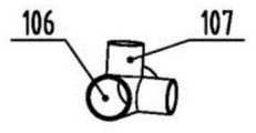
As an embodiment of the invention, the frame of the drilling device is a frame formed by steel square pipes, and is connected by welding or angle joints; two vertical poles 103 of roof adopt the cylinder guide arm, sliding structure install respectively at the front and back both ends of the sill bar of the right side frame that sets up along the horizontal direction, each sliding structure all includes a muffjoint 105, muffjoint's first interface and the front end of the sill bar of right side frame or rear end peg graft fixedly and link to each other, muffjoint's second interface and cylinder guide arm slip 106, muffjoint's third interface and the bottom of the montant that right side frame set up along vertical direction peg graft fixedly 107.
The universal brake wheel 108 is respectively installed at the four corners of the bottom of the drilling rack, so that the device can be flexibly moved, and the advantages of simplicity and convenience in use and installation of the drilling device are fully exerted.
Install front side guide rail slider structure 401, back side guide rail slider structure 402 on the inner wall of two montants in the front and back of right side frame respectively, both ends around the guide rail of the electronic guide rail slider structure 403 of level that sets up along the horizontal direction respectively with the slider of front side guide rail slider structure 401, the slider of back side guide rail slider structure 402 is fixed continuous, the right-hand member of the guide rail of the electronic guide rail slider structure 404 of axial that sets up along the horizontal direction with the vertical parallel of roof is fixed continuous with the slider of the electronic guide rail slider structure 403 of level, the left side of the guide rail of the electronic guide rail slider structure 404 of axial can insert the slide rail sleeve or set up with the separation of slide rail sleeve. And the drill bit device is arranged on the sliding block of the axial electric guide rail sliding block structure, and a rotating shaft of the drill bit device is arranged along the vertical direction.
As an embodiment of the present invention, the drill device includes an installation base 801 fixed on the slide block of the axial electric guide rail slide block structure, a driving portion 802 is fixed on the installation base 801, an adjustable chuck 803 is connected to an output shaft of the driving portion 802, the drill is fixed on the adjustable chuck, and the size of an inner hole can be adjusted inside the adjustable chuck 802 by an adaptive chuck key, so as to realize a function of clamping drill bits 804 with different diameters. The adjustable chuck is commercially available.
The driving part 802 is provided with a speed regulating switch 805 and a reversing switch 806, the speed regulating switch 805 is used for reducing the rotating speed of a main shaft of the driving part, the reversing switch 806 is matched, and a drill bit 804 is replaced for machining, so that the tapping function of threads with the size below M10 can be realized. The driving portion 802 is a pneumatic or electric motor, and the corresponding input power source is compressed gas or electric power, which are all of the conventional structures.
In a preferred embodiment of the present invention, the front end of the driving part 802 of the drill is connected to the mounting seat 801 by two front fastening bolts; the rear end of the driving part 802 is connected with the mounting seat 801 by using an angle adjusting bolt, and the rotating shaft of the driving part 802 is ensured to be arranged along the vertical direction by adjusting the screwing-in length in the mounting process.
Step two, drilling by adopting processing equipment, comprising the following steps:
step 701, a lifting appliance is used for penetrating through an inner hole of a processed part 901 with a middle through hole to be lifted and supported on two rotating roll shafts 6;
step 702, rotating a rotating handle to drive a rotating roller shaft to rotate, so that the processed part 901 rotates around the axis of the rotating roller shaft until a radial hole to be processed on the processed part 901 is located at the lowest point of a through hole of the processed part;
step 703, manually moving the right frame to the left along the longitudinal rod cylindrical guide rod 103 of the top wall until the axial electric guide rail slider structure carries the drill bit device to penetrate through the through hole of the part 901 to be processed, and inserting the left end of the guide rail of the axial electric guide rail slider structure into the slide rail sleeve, so that the guide rail of the axial electric guide rail slider structure 404 forms a three-point type stable support structure that the horizontal electric guide rail slider structure 403 drives the upper guide rail slider structure 101 and the lower guide rail slider structure 102 when moving in the horizontal direction, and simultaneously, the guide rail of the axial electric guide rail slider structure 404 forms a three-point type stable support structure that the vertical electric guide rail slider structure 103 drives the front guide rail slider structure 401 and the rear guide rail slider structure 402 when moving in the vertical direction, so as to ensure the stable movement of the drill bit device in the horizontal and vertical directions.
Step 704, driving the axial electric guide rail sliding block structure 404 to move, enabling the axis of the drill bit to be located at a position coinciding with the end face of the right side of the machined part 901, zeroing the parameters of the axial electric guide rail sliding block structure 404, then setting the driving parameters of the axial electric guide rail sliding block structure 404 according to the axial machining size required by the radial hole 902 to be machined, ensuring that the driving parameters reach the position right above the radial hole 902 to be machined, and meeting the requirement of the axial machining size of the radial hole 902; setting driving parameters of the horizontal guide rail sliding block structure 403, so that the sliding block of the horizontal electric guide rail sliding block structure moves back and forth to a position right above a central line between two rotating roll shafts of the guide rail of the horizontal electric guide rail sliding block structure, and ensuring that the processed radial hole 902 is vertically directed to an inner hole axis; driving the vertical electric guide rail sliding block structure 103 to move, enabling the tip of the drill bit to be in contact with the inner hole wall of the workpiece, resetting the parameters of the vertical electric guide rail sliding block structure 103 to zero, and then setting the driving parameters of the vertical electric guide rail sliding block structure 103 according to the machining depth required by the radial hole 902 to be machined, namely controlling the machining feed amount of the drill bit device and ensuring the machining depth of the radial hole 602;
step 705, starting the axial electric guide rail sliding block structure, the horizontal electric guide rail sliding block structure and the vertical electric guide rail structure to perform radial hole machining; after the radial hole 902 is machined, the sliding block of the vertical electric guide rail sliding block structure is driven to move upwards, so that the drill bit exits from the radial hole 902, the step 702 is returned, the next hole is machined, and the continuous machining of the workpiece without hoisting is realized; or after the machined workpiece is hung down, the process returns to step 701 to machine the next workpiece.
Claims (8)
1. A continuous positioning drilling method for radial holes of an inner wall is characterized by comprising the following steps:
step one, preparing processing equipment, wherein the processing equipment comprises a drilling device rack, the top surface structure of the drilling device rack is a top wall with a structure like a Chinese character 'ri', the drilling device rack is arranged along the horizontal direction, a mouth-shaped left side frame (1) is arranged on a left side cross rod of the top wall, an upper guide rail sliding block structure (101) and a lower guide rail sliding block structure (102) are respectively arranged at the top and the bottom of the left side frame along the horizontal direction, the upper end and the lower end of a guide rail of a vertical electric guide rail sliding block structure (103) arranged along the vertical direction are respectively fixedly connected with a sliding block of the upper guide rail sliding block structure and a sliding block of the lower guide rail sliding block structure, a sliding rail sleeve (104) is fixed on the inner wall of the sliding block of the vertical electric guide rail sliding block structure along the horizontal direction longitudinally parallel to the top wall, two rotating roller shafts (6) are rotatably arranged between the left side cross rod (2) and the middle cross rod (3) of the top wall along the longitudinal front and back direction of the top wall at intervals, the outer side end of one rotating shaft is connected with a rotating handle (7), a mouth-shaped right side frame (5) is arranged between a middle cross rod and a right side cross rod (4) of the top wall, the front and back corners of the bottom of the right side frame are respectively connected with the front and back longitudinal rods of the top wall in a left-right sliding mode through sliding structures, the inner walls of the front and back vertical rods of the right side frame are respectively provided with a front side guide rail sliding block structure (401) and a back side guide rail sliding block structure (402), the front and back ends of a guide rail of a horizontal electric guide rail sliding block structure (403) arranged along the horizontal direction are respectively fixedly connected with a sliding block of the front side guide rail sliding block structure and a sliding block of the back side guide rail sliding block structure, the right end of a guide rail of an axial electric guide rail sliding block structure (404) arranged along the horizontal direction longitudinally parallel to the top wall is fixedly connected with a sliding block of the horizontal electric guide rail sliding block structure, the left side of the guide rail of the axial electric guide rail sliding block structure can be inserted into a sliding rail sleeve or separated from the sliding rail sleeve, a drill bit device is arranged on the sliding block of the axial electric guide rail sliding block structure, and a rotating shaft of the drill bit device is arranged along the vertical direction;
step two, drilling by adopting processing equipment, comprising the following steps:
step 701, a lifting appliance is used for penetrating through an inner hole of a machined part (901) with a middle through hole to be lifted and supported on two rotating roll shafts (6);
step 702, rotating a rotating handle to drive a rotating roller shaft to rotate, so that a machined part rotates around the axis of the rotating roller shaft to the lowest point of a radial hole to be machined in the machined part, which is located in a through hole of the machined part;
step 703, manually moving the right frame to the left side along the longitudinal rod of the top wall until the axial electric guide rail sliding block structure carries the drill bit device to penetrate through a through hole of the part to be processed, inserting the left end of the guide rail of the axial electric guide rail sliding block structure into the slide rail sleeve, so that a three-point type stable support structure with the upper guide rail sliding block structure (101) and the lower guide rail sliding block structure (102) driven by the horizontal electric guide rail sliding block structure (403) is formed when the guide rail of the axial electric guide rail sliding block structure (404) moves in the horizontal direction, and simultaneously, a three-point type stable support structure with the front side guide rail sliding block structure (401) and the rear side guide rail sliding block structure (402) driven by the vertical electric guide rail sliding block structure (103) is formed when the guide rail of the axial electric guide rail sliding block structure (404) moves in the vertical direction, so as to ensure the smooth movement of the drill bit device in the horizontal and vertical directions;
step 704, driving the axial electric guide rail sliding block structure to move, enabling the axis of the drill bit to be located at a position coinciding with the end face of the right side of the machined part, zeroing the structural parameters of the axial electric guide rail sliding block, then setting the driving parameters of the axial electric guide rail sliding block structure according to the axial machining size required by the radial hole to be machined, ensuring that the driving parameters reach the position right above the radial hole to be machined, and meeting the requirement of the axial machining size of the radial hole; setting driving parameters of a horizontal electric guide rail sliding block structure, enabling a sliding block of the horizontal electric guide rail sliding block structure to move back and forth to a position right above a central line between two rotating roll shafts of a guide rail of the horizontal electric guide rail sliding block structure, and ensuring that a processed radial hole is vertically directed to an inner hole axis; driving a vertical electric guide rail sliding block structure to move, enabling the tip of a drill bit to be in contact with the inner hole wall of a workpiece, zeroing the structural parameters of the vertical electric guide rail sliding block structure, and then setting the driving parameters of the vertical electric guide rail sliding block structure according to the required machining depth of a radial hole to be machined, namely controlling the machining feed amount of a drill bit device and ensuring the machining depth of the radial hole;
step 705, starting the axial electric guide rail sliding block structure, the horizontal electric guide rail sliding block structure and the vertical electric guide rail structure to perform radial hole machining; after the radial hole is machined, the sliding block of the vertical electric guide rail sliding block structure is driven to move upwards, so that the drill bit exits from the radial hole, the step 702 is returned, the next hole is machined, and the continuous machining of the workpiece without hoisting is realized; or after the machined workpiece is hung down, the process returns to step 701 to machine the next workpiece.
2. The continuous positional drilling method for the inner wall radial holes according to claim 1, characterized in that: two vertical poles of roof adopt the cylinder guide arm, sliding structure install respectively in the front and back both ends of the sill bar of the right side frame that sets up along the horizontal direction, each sliding structure all includes a muffjoint, muffjoint's first interface and the front end of the sill bar of right side frame or rear end grafting fixed link to each other, muffjoint's second interface slide with the cylinder guide arm, muffjoint's third interface and the bottom grafting of the montant of right side frame along vertical direction setting fixed.
3. The continuous positioning drilling method for the radial holes of the inner wall according to claim 1 or 2, characterized in that: the drill bit device comprises a mounting seat fixed on a sliding block of the axial electric guide rail sliding block structure, a driving part (802) is fixed on the mounting seat (801), an output shaft of the driving part (802) is connected with an adjustable chuck (803), and a drill bit is fixed on the adjustable chuck.
4. The continuous positional drilling method for the inner wall radial holes according to claim 3, characterized in that: the front end of the driving part of the drill bit is connected with the mounting seat through two front fastening bolts; the rear end of the driving part is connected with the mounting seat by using an angle adjusting bolt.
5. The continuous positional drilling method for the inner wall radial holes according to claim 4, characterized in that: the driving part is provided with a speed regulating switch and a reversing switch.
6. The continuous positional drilling method for the inner wall radial holes according to claim 3, characterized in that: plastic rotating rollers are wrapped on the outer surfaces of the two rotating roller shafts.
7. The continuous positional drilling method for the inner wall radial holes according to claim 3, characterized in that: the drilling device frame is a frame formed by steel square pipes and is connected by welding or an angle joint.
8. The continuous positional drilling method for the inner wall radial holes of claim 7, wherein: and universal brake wheels are respectively arranged at the four corners of the bottom of the drilling device rack.
Priority Applications (1)
| Application Number | Priority Date | Filing Date | Title |
|---|---|---|---|
| CN202110923496.XA CN113510258B (en) | 2021-08-12 | 2021-08-12 | Continuous positioning drilling method for inner wall radial hole |
Applications Claiming Priority (1)
| Application Number | Priority Date | Filing Date | Title |
|---|---|---|---|
| CN202110923496.XA CN113510258B (en) | 2021-08-12 | 2021-08-12 | Continuous positioning drilling method for inner wall radial hole |
Publications (2)
| Publication Number | Publication Date |
|---|---|
| CN113510258A CN113510258A (en) | 2021-10-19 |
| CN113510258B true CN113510258B (en) | 2022-03-15 |
Family
ID=78069018
Family Applications (1)
| Application Number | Title | Priority Date | Filing Date |
|---|---|---|---|
| CN202110923496.XA Active CN113510258B (en) | 2021-08-12 | 2021-08-12 | Continuous positioning drilling method for inner wall radial hole |
Country Status (1)
| Country | Link |
|---|---|
| CN (1) | CN113510258B (en) |
Citations (8)
| Publication number | Priority date | Publication date | Assignee | Title |
|---|---|---|---|---|
| CN102896356A (en) * | 2012-09-12 | 2013-01-30 | 上海华迅汽车配件有限公司 | Inner drilling device for processing thin-wall tube member |
| JP2013046943A (en) * | 2011-08-29 | 2013-03-07 | Cosmo Koki Co Ltd | Drilling device and method for the same |
| CN103317163A (en) * | 2013-07-17 | 2013-09-25 | 大连理工大学 | Processing device for vertical hole in inner wall of small-diameter hole |
| CN105057738A (en) * | 2015-07-21 | 2015-11-18 | 浙江大学 | Inner cavity drilled multi-cutter machining device |
| CN206200185U (en) * | 2016-12-01 | 2017-05-31 | 江西工埠机械有限责任公司 | Pipe fitting inner wall drilling machine |
| CN208034216U (en) * | 2018-01-30 | 2018-11-02 | 南京信息职业技术学院 | Cylinder body class inner walls of deep holes radial bore equipment |
| CN109692987A (en) * | 2019-03-04 | 2019-04-30 | 山东太古飞机工程有限公司 | A kind of positioning support auxiliary mould precisely to drill on aircraft |
| CN210046026U (en) * | 2019-04-26 | 2020-02-11 | 常州朱美拉模具技术有限公司 | Ring die inner and outer drilling machine |
-
2021
- 2021-08-12 CN CN202110923496.XA patent/CN113510258B/en active Active
Patent Citations (8)
| Publication number | Priority date | Publication date | Assignee | Title |
|---|---|---|---|---|
| JP2013046943A (en) * | 2011-08-29 | 2013-03-07 | Cosmo Koki Co Ltd | Drilling device and method for the same |
| CN102896356A (en) * | 2012-09-12 | 2013-01-30 | 上海华迅汽车配件有限公司 | Inner drilling device for processing thin-wall tube member |
| CN103317163A (en) * | 2013-07-17 | 2013-09-25 | 大连理工大学 | Processing device for vertical hole in inner wall of small-diameter hole |
| CN105057738A (en) * | 2015-07-21 | 2015-11-18 | 浙江大学 | Inner cavity drilled multi-cutter machining device |
| CN206200185U (en) * | 2016-12-01 | 2017-05-31 | 江西工埠机械有限责任公司 | Pipe fitting inner wall drilling machine |
| CN208034216U (en) * | 2018-01-30 | 2018-11-02 | 南京信息职业技术学院 | Cylinder body class inner walls of deep holes radial bore equipment |
| CN109692987A (en) * | 2019-03-04 | 2019-04-30 | 山东太古飞机工程有限公司 | A kind of positioning support auxiliary mould precisely to drill on aircraft |
| CN210046026U (en) * | 2019-04-26 | 2020-02-11 | 常州朱美拉模具技术有限公司 | Ring die inner and outer drilling machine |
Also Published As
| Publication number | Publication date |
|---|---|
| CN113510258A (en) | 2021-10-19 |
Similar Documents
| Publication | Publication Date | Title |
|---|---|---|
| CN101954502B (en) | CNC (Computerized Numerical Control) drilling machine for processing pipe fittings | |
| CN102266826B (en) | Arc spraying device of shaft parts | |
| CN101954600A (en) | Centering clamping mechanism of CNC (Computerized Numerical Control) drilling machine of pipe fittings | |
| CN201223974Y (en) | Automatic broacher | |
| CN211464944U (en) | Double-station full-automatic pipe connecting and processing device | |
| CN107716987B (en) | Multi-hole drilling machine capable of performing multi-face operation | |
| CN210334995U (en) | Quick clamping device for repairing roller | |
| CN201744877U (en) | Automatic positioning frame | |
| CN113510258B (en) | Continuous positioning drilling method for inner wall radial hole | |
| CN201537754U (en) | Burr removing device for inner orifice of ferrule radial aperture | |
| CN216028196U (en) | Continuous positioning and drilling device for inner wall radial hole | |
| CN107263107B (en) | Automatic processing equipment for steel pipe joint | |
| CN115026387A (en) | Semi-automatic welding equipment for gravure roller with shaft and clamping welding method of semi-automatic welding equipment | |
| CN212469820U (en) | Combined boring machine | |
| CN212636183U (en) | Drilling equipment | |
| CN210877685U (en) | Standard festival main chord drilling equipment | |
| CN1718448A (en) | Carving machine | |
| CN209812513U (en) | Intelligent drilling equipment for polymer pipe excircle in batches | |
| CN210232614U (en) | Polishing device for blank pipe of copper pipe of crystallizer | |
| CN112008810A (en) | Engraving equipment for processing wooden products and using method thereof | |
| CN213530839U (en) | Hydraulic pressure bolt formula elevating gear ring beam hole processing equipment | |
| CN213135567U (en) | Steel pipe side export product processing equipment | |
| CN103752949A (en) | Full-automation round aluminum ingot machining device and method | |
| CN116900350B (en) | Automatic drilling equipment for mechanical manufacturing and using method thereof | |
| CN220178178U (en) | Lathe clamping structure for round steel surface treatment |
Legal Events
| Date | Code | Title | Description |
|---|---|---|---|
| PB01 | Publication | ||
| PB01 | Publication | ||
| SE01 | Entry into force of request for substantive examination | ||
| SE01 | Entry into force of request for substantive examination | ||
| GR01 | Patent grant | ||
| GR01 | Patent grant |