CN113494933A - Assembly for position measurement - Google Patents
Assembly for position measurement Download PDFInfo
- Publication number
- CN113494933A CN113494933A CN202110376554.1A CN202110376554A CN113494933A CN 113494933 A CN113494933 A CN 113494933A CN 202110376554 A CN202110376554 A CN 202110376554A CN 113494933 A CN113494933 A CN 113494933A
- Authority
- CN
- China
- Prior art keywords
- scale
- fixing element
- longitudinal direction
- support
- assembly according
- Prior art date
- Legal status (The legal status is an assumption and is not a legal conclusion. Google has not performed a legal analysis and makes no representation as to the accuracy of the status listed.)
- Pending
Links
- 238000005259 measurement Methods 0.000 title claims abstract description 23
- 239000000853 adhesive Substances 0.000 claims description 6
- 230000001070 adhesive effect Effects 0.000 claims description 6
- 238000010276 construction Methods 0.000 description 4
- 239000002390 adhesive tape Substances 0.000 description 3
- 229910001374 Invar Inorganic materials 0.000 description 2
- 238000001514 detection method Methods 0.000 description 2
- 239000002241 glass-ceramic Substances 0.000 description 2
- 238000004519 manufacturing process Methods 0.000 description 2
- 239000000463 material Substances 0.000 description 2
- 229910000831 Steel Inorganic materials 0.000 description 1
- 239000006094 Zerodur Substances 0.000 description 1
- 230000001133 acceleration Effects 0.000 description 1
- 239000011324 bead Substances 0.000 description 1
- 230000008878 coupling Effects 0.000 description 1
- 238000010168 coupling process Methods 0.000 description 1
- 238000005859 coupling reaction Methods 0.000 description 1
- 230000001419 dependent effect Effects 0.000 description 1
- 238000006073 displacement reaction Methods 0.000 description 1
- 230000000694 effects Effects 0.000 description 1
- 239000011521 glass Substances 0.000 description 1
- 239000010438 granite Substances 0.000 description 1
- 239000007788 liquid Substances 0.000 description 1
- 229910052751 metal Inorganic materials 0.000 description 1
- 239000002184 metal Substances 0.000 description 1
- 150000002739 metals Chemical class 0.000 description 1
- 239000007787 solid Substances 0.000 description 1
- 239000010959 steel Substances 0.000 description 1
Images

Classifications
-
- G—PHYSICS
- G01—MEASURING; TESTING
- G01B—MEASURING LENGTH, THICKNESS OR SIMILAR LINEAR DIMENSIONS; MEASURING ANGLES; MEASURING AREAS; MEASURING IRREGULARITIES OF SURFACES OR CONTOURS
- G01B5/00—Measuring arrangements characterised by the use of mechanical techniques
- G01B5/0011—Arrangements for eliminating or compensation of measuring errors due to temperature or weight
- G01B5/0014—Arrangements for eliminating or compensation of measuring errors due to temperature or weight due to temperature
-
- G—PHYSICS
- G01—MEASURING; TESTING
- G01B—MEASURING LENGTH, THICKNESS OR SIMILAR LINEAR DIMENSIONS; MEASURING ANGLES; MEASURING AREAS; MEASURING IRREGULARITIES OF SURFACES OR CONTOURS
- G01B3/00—Measuring instruments characterised by the use of mechanical techniques
- G01B3/02—Rulers with scales or marks for direct reading
- G01B3/04—Rulers with scales or marks for direct reading rigid
-
- G—PHYSICS
- G01—MEASURING; TESTING
- G01D—MEASURING NOT SPECIALLY ADAPTED FOR A SPECIFIC VARIABLE; ARRANGEMENTS FOR MEASURING TWO OR MORE VARIABLES NOT COVERED IN A SINGLE OTHER SUBCLASS; TARIFF METERING APPARATUS; MEASURING OR TESTING NOT OTHERWISE PROVIDED FOR
- G01D5/00—Mechanical means for transferring the output of a sensing member; Means for converting the output of a sensing member to another variable where the form or nature of the sensing member does not constrain the means for converting; Transducers not specially adapted for a specific variable
- G01D5/26—Mechanical means for transferring the output of a sensing member; Means for converting the output of a sensing member to another variable where the form or nature of the sensing member does not constrain the means for converting; Transducers not specially adapted for a specific variable characterised by optical transfer means, i.e. using infrared, visible, or ultraviolet light
- G01D5/32—Mechanical means for transferring the output of a sensing member; Means for converting the output of a sensing member to another variable where the form or nature of the sensing member does not constrain the means for converting; Transducers not specially adapted for a specific variable characterised by optical transfer means, i.e. using infrared, visible, or ultraviolet light with attenuation or whole or partial obturation of beams of light
- G01D5/34—Mechanical means for transferring the output of a sensing member; Means for converting the output of a sensing member to another variable where the form or nature of the sensing member does not constrain the means for converting; Transducers not specially adapted for a specific variable characterised by optical transfer means, i.e. using infrared, visible, or ultraviolet light with attenuation or whole or partial obturation of beams of light the beams of light being detected by photocells
- G01D5/347—Mechanical means for transferring the output of a sensing member; Means for converting the output of a sensing member to another variable where the form or nature of the sensing member does not constrain the means for converting; Transducers not specially adapted for a specific variable characterised by optical transfer means, i.e. using infrared, visible, or ultraviolet light with attenuation or whole or partial obturation of beams of light the beams of light being detected by photocells using displacement encoding scales
- G01D5/34746—Linear encoders
- G01D5/34753—Carriages; Driving or coupling means
-
- G—PHYSICS
- G01—MEASURING; TESTING
- G01B—MEASURING LENGTH, THICKNESS OR SIMILAR LINEAR DIMENSIONS; MEASURING ANGLES; MEASURING AREAS; MEASURING IRREGULARITIES OF SURFACES OR CONTOURS
- G01B21/00—Measuring arrangements or details thereof, where the measuring technique is not covered by the other groups of this subclass, unspecified or not relevant
- G01B21/02—Measuring arrangements or details thereof, where the measuring technique is not covered by the other groups of this subclass, unspecified or not relevant for measuring length, width, or thickness
-
- G—PHYSICS
- G01—MEASURING; TESTING
- G01B—MEASURING LENGTH, THICKNESS OR SIMILAR LINEAR DIMENSIONS; MEASURING ANGLES; MEASURING AREAS; MEASURING IRREGULARITIES OF SURFACES OR CONTOURS
- G01B3/00—Measuring instruments characterised by the use of mechanical techniques
- G01B3/002—Details
- G01B3/004—Scales; Graduations
-
- G—PHYSICS
- G01—MEASURING; TESTING
- G01D—MEASURING NOT SPECIALLY ADAPTED FOR A SPECIFIC VARIABLE; ARRANGEMENTS FOR MEASURING TWO OR MORE VARIABLES NOT COVERED IN A SINGLE OTHER SUBCLASS; TARIFF METERING APPARATUS; MEASURING OR TESTING NOT OTHERWISE PROVIDED FOR
- G01D5/00—Mechanical means for transferring the output of a sensing member; Means for converting the output of a sensing member to another variable where the form or nature of the sensing member does not constrain the means for converting; Transducers not specially adapted for a specific variable
- G01D5/12—Mechanical means for transferring the output of a sensing member; Means for converting the output of a sensing member to another variable where the form or nature of the sensing member does not constrain the means for converting; Transducers not specially adapted for a specific variable using electric or magnetic means
- G01D5/14—Mechanical means for transferring the output of a sensing member; Means for converting the output of a sensing member to another variable where the form or nature of the sensing member does not constrain the means for converting; Transducers not specially adapted for a specific variable using electric or magnetic means influencing the magnitude of a current or voltage
- G01D5/20—Mechanical means for transferring the output of a sensing member; Means for converting the output of a sensing member to another variable where the form or nature of the sensing member does not constrain the means for converting; Transducers not specially adapted for a specific variable using electric or magnetic means influencing the magnitude of a current or voltage by varying inductance, e.g. by a movable armature
-
- G—PHYSICS
- G01—MEASURING; TESTING
- G01D—MEASURING NOT SPECIALLY ADAPTED FOR A SPECIFIC VARIABLE; ARRANGEMENTS FOR MEASURING TWO OR MORE VARIABLES NOT COVERED IN A SINGLE OTHER SUBCLASS; TARIFF METERING APPARATUS; MEASURING OR TESTING NOT OTHERWISE PROVIDED FOR
- G01D5/00—Mechanical means for transferring the output of a sensing member; Means for converting the output of a sensing member to another variable where the form or nature of the sensing member does not constrain the means for converting; Transducers not specially adapted for a specific variable
- G01D5/12—Mechanical means for transferring the output of a sensing member; Means for converting the output of a sensing member to another variable where the form or nature of the sensing member does not constrain the means for converting; Transducers not specially adapted for a specific variable using electric or magnetic means
- G01D5/244—Mechanical means for transferring the output of a sensing member; Means for converting the output of a sensing member to another variable where the form or nature of the sensing member does not constrain the means for converting; Transducers not specially adapted for a specific variable using electric or magnetic means influencing characteristics of pulses or pulse trains; generating pulses or pulse trains
- G01D5/24428—Error prevention
- G01D5/24433—Error prevention by mechanical means
- G01D5/24442—Error prevention by mechanical means by mounting means
-
- G—PHYSICS
- G01—MEASURING; TESTING
- G01D—MEASURING NOT SPECIALLY ADAPTED FOR A SPECIFIC VARIABLE; ARRANGEMENTS FOR MEASURING TWO OR MORE VARIABLES NOT COVERED IN A SINGLE OTHER SUBCLASS; TARIFF METERING APPARATUS; MEASURING OR TESTING NOT OTHERWISE PROVIDED FOR
- G01D5/00—Mechanical means for transferring the output of a sensing member; Means for converting the output of a sensing member to another variable where the form or nature of the sensing member does not constrain the means for converting; Transducers not specially adapted for a specific variable
- G01D5/26—Mechanical means for transferring the output of a sensing member; Means for converting the output of a sensing member to another variable where the form or nature of the sensing member does not constrain the means for converting; Transducers not specially adapted for a specific variable characterised by optical transfer means, i.e. using infrared, visible, or ultraviolet light
- G01D5/32—Mechanical means for transferring the output of a sensing member; Means for converting the output of a sensing member to another variable where the form or nature of the sensing member does not constrain the means for converting; Transducers not specially adapted for a specific variable characterised by optical transfer means, i.e. using infrared, visible, or ultraviolet light with attenuation or whole or partial obturation of beams of light
- G01D5/34—Mechanical means for transferring the output of a sensing member; Means for converting the output of a sensing member to another variable where the form or nature of the sensing member does not constrain the means for converting; Transducers not specially adapted for a specific variable characterised by optical transfer means, i.e. using infrared, visible, or ultraviolet light with attenuation or whole or partial obturation of beams of light the beams of light being detected by photocells
- G01D5/347—Mechanical means for transferring the output of a sensing member; Means for converting the output of a sensing member to another variable where the form or nature of the sensing member does not constrain the means for converting; Transducers not specially adapted for a specific variable characterised by optical transfer means, i.e. using infrared, visible, or ultraviolet light with attenuation or whole or partial obturation of beams of light the beams of light being detected by photocells using displacement encoding scales
- G01D5/34707—Scales; Discs, e.g. fixation, fabrication, compensation
- G01D5/34715—Scale reading or illumination devices
Abstract
The invention relates to an assembly for position measurement. The assembly comprises a support (10), a scale (12) arranged on the support (10), and a plurality of fixing elements (16) for fixing the scale (12) at the support (10). The scale (12) extends in a longitudinal direction (X). The scale (12) has a measuring graduation (14) for measuring a position at least in the longitudinal direction (X). The support (10) has a plurality of individual segments (10.1-10.7). The fixing elements (16) are arranged on individual sections (10.1-10.7) of the carrier (10).
Description
Technical Field
The present invention relates to an assembly according to the preamble of claim 1.
Background
Document WO 2006/133753 a1 discloses an assembly for position measurement with a carriage body and a plurality of fixing elements arranged along and at both sides of the scale. A yield hinge (festkoerpegelenk) is arranged between the support body and the fastening element, which couples the fastening element and thus the scale to the support body in a manner that it can be pivoted in the measuring direction X.
A disadvantage of the known measuring assembly is that the support body is constructed in one piece. This results in a relatively cost intensive manufacture of the support body or the measuring assembly on the one hand. On the other hand, the implementation of a thermal decoupling between the support body (or measuring assembly) and the base body (for example a gantry (maschinenbet)) is relatively complicated. Since structural measures are typically required for this, for example the application of additional solid hinges. Thermal decoupling is again a prerequisite for high accuracy of the position measurement.
Disclosure of Invention
The invention is based on the object of specifying an assembly for position measurement which has a simple and cost-effective design and with which precise position measurements can be carried out.
According to the invention, this object is achieved by an assembly having the features of claim 1.
The assembly constructed according to the invention comprises a support, a scale arranged on the support and a plurality of fixing elements for fixing the scale at the support. The scale extends in a longitudinal direction. The scale has a measurement scale (Messteilung) for position measurement at least in the longitudinal direction. The stent has a plurality of individual segments. The fixing elements are arranged on individual sections of the carrier.
Preferably, the individual segments of the carrier are each associated with a fastening element of the plurality of fastening elements or with pairs of fastening elements arranged opposite one another in the transverse direction (which runs perpendicular to the longitudinal direction).
It is advantageous if the individual segments of the holder are arranged longitudinally separated from one another.
Furthermore, it is advantageous if the individual segments of the stent are arranged distributed in the longitudinal direction, for example equidistantly.
Alternatively, the individual sections of the stent may be arranged non-equidistantly. For example, the distance between the individual sections of the holder in the vicinity of the fixing point (that is to say the point at which the position of the scale is fixedly located) is greater than the distance between the individual sections of the holder at the two free ends of the scale.
The fixing element preferably has a plurality of flexible hinges for (local) thermally decoupled buckling hinges between the support and the scale.
In order to positionally fix the scale relative to the holder, the fixing element can be provided in the form of an adhesive track (klebereaup).
The individual sections of the bracket may also be referred to as discrete plates.
The measuring graduation is preferably used for position measurement in the longitudinal direction (that is to say the degree of freedom X) and in the transverse direction (that is to say the degree of freedom Y). Alternatively, the measurement scale (associated with the respective detection unit (abbasteinheit)) can be configured such that a position measurement in 6 degrees of freedom (that is to say in the degrees of freedom X, Y, Z, RX, RY, RZ) is achieved.
The measurement scale is, for example, an incremental scale (inkmentateilung). Alternatively, the measurement scale may be an absolute scale, for example configured as a pseudo-random code.
The invention achieves a high level of reproducibility of the linearity (Geradheit) of the scale. It is particularly advantageous if the scale has measuring scales for position measurement in the longitudinal direction as well as in the transverse direction. In this regard, the measurement scale comprises a plurality of scale structures arranged periodically along a first measurement direction (main measurement direction or X-direction) and a plurality of scale structures arranged periodically along a second measurement direction (Y-direction). The first measuring direction and the second measuring direction extend perpendicular to each other. The graduation structures in particular respectively comprise graduation marks (Teilungsstrich).
Advantageous embodiments of the invention emerge from the dependent claims.
Drawings
The details and advantages of the assembly according to the invention result from the following description of an embodiment with reference to the drawings. Wherein:
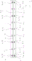
FIG. 1 shows a perspective view of an assembly constructed in accordance with the present invention with a support, a scale disposed on the support, and a plurality of fixation elements;
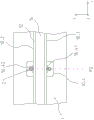
FIG. 2 shows a top view of the assembly according to FIG. 1;
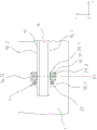
FIG. 3a shows a perspective view of a single section of a stent with a first fixation element and a second fixation element;
FIG. 3b shows a top view of a single section of the stent according to FIG. 3 a;
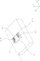
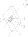
fig. 4a shows a perspective view of a further individual section of the support with a third and a fourth fixing element; and
fig. 4b shows a top view of a further individual section of the support according to fig. 4 a.
Detailed Description
Identical elements or elements having the same function are provided with the same reference symbols in the figures.
An embodiment of the invention is explained below with reference to fig. 1 and 2. An assembly constructed in accordance with the present invention comprises a support 10, a scale 12 arranged on the support 10 and a plurality of fixing elements 16. The scale 12 extends in a longitudinal direction (main measuring direction) X and has a measuring graduation 14 arranged in a measuring graduation plane, that is to say an X/Y plane. The measuring graduation 14 is designed as a photodetective incremental graduation for high-precision position measurement in the longitudinal direction X and additionally in a second transverse direction Y running perpendicularly thereto. The scale 12 is preferably made with a negligibly small coefficient of thermal expansion (in particular with a coefficient of thermal expansion of less than 1.5 x 10 in the temperature range 0-50 ℃)-6K-1But especially less than 0.1 x 10⁻⁶K-1Coefficient of thermal expansion α). Such materials are glass or glass-ceramics (e.g. glass-ceramics (Zerodur)) or metals such as Invar (Invar).
The stent 10 is preferably formed from a band of about 10.5 x 10⁻⁶K-1Steel having a thermal expansion coefficient of (1).
The support 10 has a plurality of individual plate-shaped sections 10.1 to 10.7. The scale 12 has a rectangular cross section with two side faces (which each extend in the longitudinal direction X) 18.1,18.2 lying opposite one another (see fig. 2).
The fixing element 16 serves to fix the scale 12 to the support 10. The fixation elements 16 include a first set of fixation elements 16.11-16.71 and a second set of fixation elements 16.12-16.72. The fixing elements 16.11 to 16.71 and 16.12 to 16.72 are arranged on two side faces 18.1,18.2 of the scale 12 which face one another (see fig. 2). As shown in fig. 1, the fixing elements 16 are arranged on the individual segments 10.1 to 10.7 of the carrier 10.
The assembly shown in fig. 1 is arranged on a base body 1 (e.g. a frame). In order to fix the assembly to the base body 1, a bolt 2 is provided. The bolts 2 extend through the individual sections 10.1-10.7 as far as into the base body 1. The base body 1 is made of granite (Granit), for example.
The multi-part carrier body (i.e. the carrier 10) is realized by the assembly according to the invention. The multi-part construction is advantageous compared to the one-part construction according to the prior art, so that the manufacturing of the bracket body and thus the assembly is relatively cost-effective. Furthermore, the multi-part construction has the advantage that thermal decoupling between the carrier 10 and the base body 1 can be achieved in a simple manner. Additional structural measures, such as additional articulated joints, can be dispensed with in particular.
Advantageously, the individual segments (individual plates) 10.1 to 10.7 of the carrier 10 are relatively small and can be simply moved together with the main body 1 approximately at any point (that is to say locally at the respective X position). In contrast to the prior art, the thermal decoupling just mentioned is thus achieved without additional structural measures being applied.
Between the individual sections 10.1 to 10.7 of the carrier 10, further sections 11.1 to 11.6 of the carrier 10 (so-called intermediate sections) are arranged. The intermediate sections 11.1 to 11.6 are fastened to the base body 1 by means of screws 4 and serve to support the scale 12 in the height direction (i.e. Z direction). In this case, the intermediate sections 11.1 to 11.6 are designed to carry the scale 12 in the height direction Z rigidly on the support 10 and thus to be rigidly connected to the base body 1 in the intermediate position (i.e. in the position between the individual sections 10.1 to 10.7 of the support 10) via attachment means (Haftmittel). The intermediate sections 11.1-11.6 may also be omitted.
With reference to fig. 1, the individual segments 10.1-10.7 of the support 10 are respectively associated with pairs of fixing elements 16.11,16.12-16.71,16.72 of the plurality of fixing elements 16 which are arranged opposite one another in the transverse direction Y. In particular, the fastening elements 16.11,16.12 to 16.71,16.72 arranged in pairs are arranged on the respective associated individual sections 10.1 to 10.7 of the carrier 10.
Alternatively, a single section 10.1-10.7 of the carrier 10 may be associated with only one of the plurality of fixing elements 16 (e.g., fixing elements 16.11-16.71 or fixing elements 16.12-16.72), respectively.
As shown in fig. 1, the individual sections 10.1 to 10.7 of the support 10 are arranged separately from one another in the longitudinal direction X. Furthermore, the individual segments 10.1 to 10.7 of the stent 10 are distributed, in particular equidistantly, in the longitudinal direction X. The spacing between the individual segments 10.1-10.7 of the carrier 10 is in this case, for example, 100 mm.
The fixing element 16 shown in fig. 1 has a first fixing element 16.11 arranged at a first side surface 18.1 of the scale 12 and a second fixing element 16.12 arranged at a second side surface 18.2 of the scale 12. The first fixing element 16.11 and the second fixing element 16.12 are arranged opposite one another in the transverse direction Y. The following embodiments are similarly applicable to the fixation elements 16.21,16.22-16.71,16.72 (except 16.41,16.42) arranged in pairs.
The first fixing element 16.11 is configured to carry the scale 12 freely movably in the longitudinal direction X relative to the carriage 10 at a position P1 (see fig. 3 b). Furthermore, the first fixing element 16.11 is configured to rigidly carry the scale 12 at the support 10 in the transverse direction Y. In this case, the first fastening element 16.11 is in particular designed as a drooping hinge.
With regard to fig. 3b, the first fixing element 16.11 has a first section 20.1 which is fixed by a material-fit connection at the first side surface 18.1 of the scale 12. Furthermore, the first fastening element 16.11 has a second portion 20.2 which is fastened by a material-fit connection to the upper surface 22 of the portion 10.1 of the individual portions 10.1-10.7 of the carrier 10 associated with the first fastening element 16.11 (see fig. 3a and 3 b). The material-fit connection is in particular an adhesive connection.
The second fixing element 16.12 is configured to carry the scale 12 freely movably in the longitudinal direction X relative to the carriage 10 in the first position P1. Furthermore, the second fixing element 16.12 is configured to rigidly carry the scale 12 at the support 10 in the transverse direction Y. In this connection, the second fastening element 16.12 is in particular designed as a drooping hinge.
The second fixing element 16.12 is connected to the scale 12 and to the section 10.1 of the support 10, similarly to the first fixing element 16.11.
With respect to fig. 3a, the assembly has first attachment means 24.1 for securing the scale 12 at the support 10. The first attachment means 24.1 are arranged on the one hand on the upper surface 22 of the section 10.1 of the carrier 10 and on the other hand between the first fixing element 16.11 and the second fixing element 16.12. The first attachment means 24.1 are configured strip-like and extend substantially in the transverse direction Y. For example, the first adhesive component 24.1 has a strip of double-sided adhesive tape, in particular transfer lebeband.
The first attachment means 24.1 are arranged correspondingly on each of the sections 10.1-10.7 (except 10.4) of the holder 10.
The fastening element 16 shown in fig. 1 furthermore has a third fastening element 16.41 arranged on the first lateral surface 18.1 of the scale 12 and a fourth fastening element 16.42 arranged on the second lateral surface 18.2 of the scale 12. The third fixing element 16.41 and the fourth fixing element 16.42 are arranged opposite one another in the transverse direction Y. The fixing elements 16.41,16.42 arranged in pairs are associated with or arranged on the segments 10.4 of the carrier 10.
The third fixing element 16.41 is configured to rigidly carry the scale 12 at the support 10 in the longitudinal direction X and in the transverse direction Y at a second position P2 (see fig. 4b) different from the first position P1. The fourth fixing element 16.42 is configured to rigidly carry the scale 12 at the support 10 in the longitudinal direction X and in the transverse direction Y at the second position P2. For example, the third fixing element 16.41 and the fourth fixing element 16.42 each have an adhesive bead, in particular a fillet weld (Kehlnaht), for connecting the scale 12 to the section 10.4 of the support 10.
With regard to fig. 4a, the assembly furthermore has a second attachment means 24.2 and a third attachment means 24.3 for fixing the scale 12 at the support 10. The second attachment means 24.2 and the third attachment means 24.3 are arranged on the one hand on the upper surface of the section 10.4 of the support 10 and on the other hand between the third fixing element 16.41 and the fourth fixing element 16.42. The second attachment means 24.2 and the third attachment means 24.3 are configured in the form of respective strips and extend substantially in the longitudinal direction X. For example, the second attachment means 24.2 and the third attachment means 24.3 each have a strip of double-sided adhesive tape, in particular transfer tape.
The first to third attachment means 24.1-24.3 serve to support the fixing of the scale 12 by the first to fourth fixing elements 16.11,16.12,16.41, 16.42. This results in a particularly stable and reliable construction of the assembly.
Furthermore, the first to third attachment means 24.1-24.3 serve to decouple the scale 12 from the support 10 in order to prevent frictional effects (or the generation of defined shear forces).
For example, the first to third attachment means 24.1-24.3 each have a strip with a double-sided adhesive tape of 10mm width.
Instead of the above-mentioned manoeuvring tapes, it is also possible to apply very soft adhesives with mixed balls or liquid manoeuvring tapes.
The third and fourth fixing elements 16.41,16.42 may alternatively also be configured such that they carry or are coupled to the scale 12 at the support 10 rigidly in the longitudinal direction X, but flexibly (softly) in the transverse direction Y in the second position P2. Such coupling is disclosed in particular in document EP 3026389 a 1.
The advantage of the invention is that the scale 12 is connected to the base body 1 by the fixing element 16 under lateral forces (e.g. lateral acceleration) without significant lateral displacement and scale deflection in the Y direction. This is advantageous in particular for position measurements of the measurement scale 14 in the longitudinal direction (degree of freedom X) and in the transverse direction (degree of freedom Y).
The base body 1 is preferably composed of a material with a coefficient of thermal expansion that is smaller than the coefficient of thermal expansion of the holder 10.
The present invention is not limited to the principle of photo-detection. The measuring graduation 14 can also be designed to be detectable, in particular magnetically or inductively.
Claims (15)
1. An assembly, with:
a support (10) for supporting the support,
a scale (12) arranged on the support (10), wherein the scale (12) extends in a longitudinal direction (X), and wherein the scale (12) has a measurement scale (14) for measuring a position at least in the longitudinal direction (X), and
a plurality of fixing elements (16) for fixing the scale (12) at the support (10),
characterized in that the carrier (10) has a plurality of individual segments (10.1-10.7) and the fixing element (16) is arranged on an individual segment (10.1-10.7) of the carrier (10).
2. Assembly according to claim 1, wherein a single section (10.1-10.7) of the carrier (10) is associated with a respective one of the plurality of fixing elements (16) or with pairs of fixing elements (16.11,16.12-16.71,16.72) arranged opposite one another in a transverse direction (Y) extending perpendicular to the longitudinal direction (X).
3. Assembly according to claim 1 or 2, wherein the individual sections (10.1-10.7) of the bracket (10) are arranged separated from each other in the longitudinal direction (X).
4. Assembly according to one of the preceding claims, wherein the individual sections (10.1-10.7) of the bracket (10) are arranged distributed, in particular equidistantly, in the longitudinal direction (X).
5. Assembly according to any one of the preceding claims, wherein the fixing element (16) has at least one first fixing element (16.11) arranged at a first side surface (18.1) of the scale (12) extending in the longitudinal direction (X).
6. Assembly according to claim 5, wherein the first fixing element (16.11) is configured to carry the scale (12) freely movable in relation to the carriage (10) in the longitudinal direction (X) in a first position (P1).
7. Assembly according to claim 5 or 6, wherein the first fixing element (16.11) is configured to rigidly carry the scale (12) at the support (10) in a transverse direction (Y) running perpendicular to the longitudinal direction (X).
8. The assembly according to any one of claims 5 to 7, wherein the first fixing element (16.11) has a first section (20.1) fixed at a first side surface (18.1) of the scale (12) by a material-fit connection.
9. Assembly according to one of claims 5 to 8, wherein the first fixing element (16.11) has a second section (20.2), wherein the second section (20.2) is fixed at an upper surface (22) of a section (10.1) of the individual sections (10.1-10.7) of the bracket (10) by a material-fit connection.
10. An assembly according to claim 8 or 9, wherein the material-engaging connection is an adhesive connection.
11. Assembly according to one of claims 5 to 10, wherein the fixing element (16) has a second fixing element (16.12) arranged at a second side surface (18.2) of the scale (12) extending in a longitudinal direction (X), wherein the first fixing element (16.11) and the second fixing element (16.12) are arranged opposite each other in a transverse direction (Y) extending perpendicular to the longitudinal direction (X).
12. The assembly according to claim 11, wherein the first and second fixation elements (16.11, 16.12) each have a drooping hinge.
13. Assembly according to claim 11 or 12, wherein the assembly has at least one first attachment means (24.1) for fixing the scale (12) at the support (10), wherein the first attachment means (24.1) is arranged at an upper surface (22) of a section (10.1) of the single section (10.1-10.7) of the support (10) associated with the first fixing element (16.11) and the second fixing element (16.12) and between the first fixing element (16.11) and the second fixing element (16.12).
14. Assembly according to claim 13, wherein the first attachment means (24.1) are configured strip-shaped and extend substantially in a transverse direction (Y) running perpendicular to the longitudinal direction (X).
15. Assembly according to any one of claims 6 to 14, wherein the fixing element (16) has at least one third fixing element (16.41) arranged at a first side surface (18.1) of the scale (12), wherein the third fixing element (16.41) is configured to rigidly carry the scale (12) at the support (10) in a longitudinal direction (X) at a second position (P2) different from the first position (P1) and in a transverse direction (Y) extending perpendicular to the longitudinal direction (X).
Applications Claiming Priority (2)
| Application Number | Priority Date | Filing Date | Title |
|---|---|---|---|
| EP20168807.4 | 2020-04-08 | ||
| EP20168807.4A EP3892962B1 (en) | 2020-04-08 | 2020-04-08 | Assembly for position measurement |
Publications (1)
| Publication Number | Publication Date |
|---|---|
| CN113494933A true CN113494933A (en) | 2021-10-12 |
Family
ID=70277241
Family Applications (1)
| Application Number | Title | Priority Date | Filing Date |
|---|---|---|---|
| CN202110376554.1A Pending CN113494933A (en) | 2020-04-08 | 2021-04-08 | Assembly for position measurement |
Country Status (7)
| Country | Link |
|---|---|
| US (1) | US11733019B2 (en) |
| EP (1) | EP3892962B1 (en) |
| JP (1) | JP2021167804A (en) |
| KR (1) | KR20210125900A (en) |
| CN (1) | CN113494933A (en) |
| DE (1) | DE102021200545A1 (en) |
| ES (1) | ES2943517T3 (en) |
Families Citing this family (1)
| Publication number | Priority date | Publication date | Assignee | Title |
|---|---|---|---|---|
| EP4286798A1 (en) | 2022-06-01 | 2023-12-06 | Dr. Johannes Heidenhain GmbH | Assembly for position measurement |
Family Cites Families (23)
| Publication number | Priority date | Publication date | Assignee | Title |
|---|---|---|---|---|
| AT396631B (en) * | 1984-07-06 | 1993-10-25 | Rsf Elektronik Gmbh | INCREMENTAL MEASURING SYSTEM |
| DE3427411A1 (en) * | 1984-07-25 | 1986-02-06 | Dr. Johannes Heidenhain Gmbh, 8225 Traunreut | MEASURING DEVICE |
| AT394446B (en) * | 1990-10-11 | 1992-03-25 | Rsf Elektronik Gmbh | INCREMENTAL LENGTH MEASURING SYSTEM |
| FI91325C (en) * | 1992-04-07 | 1994-06-10 | Partek Cargotec Oy | Position scale and optical read sensor to read this position scale |
| JP3134590B2 (en) * | 1993-05-13 | 2001-02-13 | ソニー・プレシジョン・テクノロジー株式会社 | Scale equipment |
| EP0668486A3 (en) * | 1994-02-22 | 1997-07-30 | Heidenhain Gmbh Dr Johannes | Device for measuring lengths or angles. |
| DE19628765B4 (en) * | 1996-07-17 | 2007-04-05 | Braun, Paul-Wilhelm, Dipl.-Ing. | Method and device for determining the position of non-rectilinearly moving, in particular rotating machine parts |
| DE19802036B4 (en) | 1998-01-21 | 2006-11-30 | Dr. Johannes Heidenhain Gmbh | Method and device for the mechanical adjustment of graduation carriers |
| JP4869505B2 (en) * | 2001-06-27 | 2012-02-08 | 株式会社ミツトヨ | Encoder sliding mechanism |
| GB0413711D0 (en) * | 2004-06-21 | 2004-07-21 | Renishaw Plc | Scale and readhead apparatus |
| GB0415141D0 (en) * | 2004-07-06 | 2004-08-11 | Renishaw Plc | Scale reading apparatus |
| DE102005027025B4 (en) | 2005-06-11 | 2015-04-30 | Dr. Johannes Heidenhain Gmbh | Mount for a scale |
| JP4982554B2 (en) | 2006-03-29 | 2012-07-25 | ドクトル・ヨハネス・ハイデンハイン・ゲゼルシヤフト・ミツト・ベシユレンクテル・ハフツング | Method for holding scale on carrier and assembly comprising carrier and scale |
| DE102007002772A1 (en) * | 2006-03-29 | 2007-10-04 | Dr. Johannes Heidenhain Gmbh | Measurement rod holding method, involves creating electrical voltage between electrodes of measurement rod and carrier, and forming difference of potential between rod and carrier to generate holding force for electrostatic clamp |
| US8011112B2 (en) * | 2006-12-07 | 2011-09-06 | Leica Geosystems Ag | Method and apparatus for determining positions |
| DE102008015820B4 (en) * | 2008-03-27 | 2013-02-28 | Fette Compacting Gmbh | Apparatus and method for measuring the vertical position of upper and lower punches of a rotary tablet press |
| US7994775B2 (en) * | 2009-01-08 | 2011-08-09 | Hiwin Mikrosystem Corp. | Magnetic sensor |
| CN101532815B (en) * | 2009-04-24 | 2011-05-11 | 广州市诺信数字测控设备有限公司 | Magnetoscale supporting plate structure |
| DE102014209004A1 (en) * | 2014-05-13 | 2015-11-19 | Dr. Johannes Heidenhain Gmbh | Position measuring device |
| ES2621078T3 (en) | 2014-11-26 | 2017-06-30 | Dr. Johannes Heidenhain Gmbh | Length measuring device |
| US9791254B2 (en) * | 2014-12-27 | 2017-10-17 | Mitutoyo Corporation | Scale fixating device |
| JP6990024B2 (en) * | 2016-12-22 | 2022-01-12 | 株式会社ミツトヨ | Linear expansion coefficient measuring method and measuring device |
| WO2022140548A1 (en) * | 2020-12-22 | 2022-06-30 | Heartland Ag Tech, Inc. | Modular kinematic and telemetry system for an irrigation system |
-
2020
- 2020-04-08 ES ES20168807T patent/ES2943517T3/en active Active
- 2020-04-08 EP EP20168807.4A patent/EP3892962B1/en active Active
-
2021
- 2021-01-21 DE DE102021200545.4A patent/DE102021200545A1/en active Pending
- 2021-01-29 JP JP2021012828A patent/JP2021167804A/en active Pending
- 2021-02-22 KR KR1020210023274A patent/KR20210125900A/en active Search and Examination
- 2021-03-22 US US17/207,761 patent/US11733019B2/en active Active
- 2021-04-08 CN CN202110376554.1A patent/CN113494933A/en active Pending
Also Published As
| Publication number | Publication date |
|---|---|
| EP3892962B1 (en) | 2023-03-08 |
| US11733019B2 (en) | 2023-08-22 |
| ES2943517T3 (en) | 2023-06-13 |
| KR20210125900A (en) | 2021-10-19 |
| EP3892962A1 (en) | 2021-10-13 |
| US20210318109A1 (en) | 2021-10-14 |
| JP2021167804A (en) | 2021-10-21 |
| DE102021200545A1 (en) | 2021-10-14 |
Similar Documents
| Publication | Publication Date | Title |
|---|---|---|
| US9772204B2 (en) | Length-measuring device | |
| US5979238A (en) | Strip-shaped resiliently flexible measuring tape for length--or angle-measuring devices | |
| US8040099B2 (en) | Position device in gantry type of construction | |
| US4815213A (en) | Apparatus for temperature compensation of sensing means of a machine | |
| US20110067255A1 (en) | Linear encoder | |
| JP2000275064A (en) | Location measuring device | |
| US6349481B1 (en) | Device and method for attaching a scale | |
| CN103492831A (en) | Apparatus and method for measuring the thickness of a measurement object | |
| WO2007111656B1 (en) | Temperature compensation system for a coordinate measuring machine | |
| JP4931916B2 (en) | Scale holder | |
| US20130019489A1 (en) | Length measuring device | |
| CN113494933A (en) | Assembly for position measurement | |
| JP2675245B2 (en) | Length measuring machine | |
| US7765709B2 (en) | Measuring apparatus | |
| JP7154879B2 (en) | Portal structure positioning device | |
| CN102317034B (en) | Encoder scale member and method for mounting | |
| US7475489B2 (en) | Scanning system of a position measuring device | |
| US6433875B1 (en) | Measuring device for measuring the accuracy of the position and track of a moving machine element | |
| US11519763B2 (en) | Assembly including a main support, an intermediate support disposed on the main support, and a scale disposed on the intermediate support | |
| US5119566A (en) | Stationary gantry for a precision coordinate measuring instrument | |
| EP1659373A1 (en) | Linear encoder with temperature compensation | |
| CN101509792A (en) | Sample traveling stage with flexure mechanism module to absorb the deformation of the slide | |
| US20230392914A1 (en) | Assembly for position measurement | |
| JPH0749457Y2 (en) | Laser mirror mounting structure | |
| JPS61254811A (en) | Mounting means of scale for length measurement system |
Legal Events
| Date | Code | Title | Description |
|---|---|---|---|
| PB01 | Publication | ||
| PB01 | Publication | ||
| SE01 | Entry into force of request for substantive examination | ||
| SE01 | Entry into force of request for substantive examination |