EP1659373A1 - Linear encoder with temperature compensation - Google Patents
Linear encoder with temperature compensation Download PDFInfo
- Publication number
- EP1659373A1 EP1659373A1 EP04380233A EP04380233A EP1659373A1 EP 1659373 A1 EP1659373 A1 EP 1659373A1 EP 04380233 A EP04380233 A EP 04380233A EP 04380233 A EP04380233 A EP 04380233A EP 1659373 A1 EP1659373 A1 EP 1659373A1
- Authority
- EP
- European Patent Office
- Prior art keywords
- support piece
- positioning module
- thermal expansion
- expansion coefficient
- graduated scale
- Prior art date
- Legal status (The legal status is an assumption and is not a legal conclusion. Google has not performed a legal analysis and makes no representation as to the accuracy of the status listed.)
- Granted
Links
- 239000000853 adhesive Substances 0.000 claims abstract description 52
- 230000001070 adhesive effect Effects 0.000 claims abstract description 52
- 230000003287 optical effect Effects 0.000 claims abstract description 30
- 238000001514 detection method Methods 0.000 claims abstract description 22
- 239000000463 material Substances 0.000 claims description 12
- 238000010008 shearing Methods 0.000 claims description 9
- 238000006073 displacement reaction Methods 0.000 claims description 8
- PNEYBMLMFCGWSK-UHFFFAOYSA-N aluminium oxide Inorganic materials [O-2].[O-2].[O-2].[Al+3].[Al+3] PNEYBMLMFCGWSK-UHFFFAOYSA-N 0.000 claims description 4
- 230000000694 effects Effects 0.000 description 9
- 230000001681 protective effect Effects 0.000 description 4
- 239000011521 glass Substances 0.000 description 3
- 230000004048 modification Effects 0.000 description 3
- 238000012986 modification Methods 0.000 description 3
- 238000000926 separation method Methods 0.000 description 3
- 230000005483 Hooke's law Effects 0.000 description 2
- 230000014509 gene expression Effects 0.000 description 2
- XUIMIQQOPSSXEZ-UHFFFAOYSA-N Silicon Chemical compound [Si] XUIMIQQOPSSXEZ-UHFFFAOYSA-N 0.000 description 1
- 230000006835 compression Effects 0.000 description 1
- 238000007906 compression Methods 0.000 description 1
- 230000001143 conditioned effect Effects 0.000 description 1
- 230000008602 contraction Effects 0.000 description 1
- 229910052593 corundum Inorganic materials 0.000 description 1
- 238000011156 evaluation Methods 0.000 description 1
- 229910052710 silicon Inorganic materials 0.000 description 1
- 239000010703 silicon Substances 0.000 description 1
- 229910001845 yogo sapphire Inorganic materials 0.000 description 1
Images

Classifications
-
- G—PHYSICS
- G01—MEASURING; TESTING
- G01D—MEASURING NOT SPECIALLY ADAPTED FOR A SPECIFIC VARIABLE; ARRANGEMENTS FOR MEASURING TWO OR MORE VARIABLES NOT COVERED IN A SINGLE OTHER SUBCLASS; TARIFF METERING APPARATUS; MEASURING OR TESTING NOT OTHERWISE PROVIDED FOR
- G01D5/00—Mechanical means for transferring the output of a sensing member; Means for converting the output of a sensing member to another variable where the form or nature of the sensing member does not constrain the means for converting; Transducers not specially adapted for a specific variable
- G01D5/26—Mechanical means for transferring the output of a sensing member; Means for converting the output of a sensing member to another variable where the form or nature of the sensing member does not constrain the means for converting; Transducers not specially adapted for a specific variable characterised by optical transfer means, i.e. using infrared, visible, or ultraviolet light
- G01D5/32—Mechanical means for transferring the output of a sensing member; Means for converting the output of a sensing member to another variable where the form or nature of the sensing member does not constrain the means for converting; Transducers not specially adapted for a specific variable characterised by optical transfer means, i.e. using infrared, visible, or ultraviolet light with attenuation or whole or partial obturation of beams of light
- G01D5/34—Mechanical means for transferring the output of a sensing member; Means for converting the output of a sensing member to another variable where the form or nature of the sensing member does not constrain the means for converting; Transducers not specially adapted for a specific variable characterised by optical transfer means, i.e. using infrared, visible, or ultraviolet light with attenuation or whole or partial obturation of beams of light the beams of light being detected by photocells
- G01D5/347—Mechanical means for transferring the output of a sensing member; Means for converting the output of a sensing member to another variable where the form or nature of the sensing member does not constrain the means for converting; Transducers not specially adapted for a specific variable characterised by optical transfer means, i.e. using infrared, visible, or ultraviolet light with attenuation or whole or partial obturation of beams of light the beams of light being detected by photocells using displacement encoding scales
- G01D5/34707—Scales; Discs, e.g. fixation, fabrication, compensation
-
- G—PHYSICS
- G01—MEASURING; TESTING
- G01B—MEASURING LENGTH, THICKNESS OR SIMILAR LINEAR DIMENSIONS; MEASURING ANGLES; MEASURING AREAS; MEASURING IRREGULARITIES OF SURFACES OR CONTOURS
- G01B5/00—Measuring arrangements characterised by the use of mechanical techniques
- G01B5/0011—Arrangements for eliminating or compensation of measuring errors due to temperature or weight
- G01B5/0014—Arrangements for eliminating or compensation of measuring errors due to temperature or weight due to temperature
Definitions
- the present invention relates to optical measuring devices of linear and angular displacements and, more specifically, to optical measuring devices that comprise a graduated scale with at least two tracks, an incremental track and an absolute track, and a detection unit with means for measuring a relative position and means for measuring an absolute position.
- Optical measuring devices that comprise a graduated scale with an incremental track and an absolute track, and a detection unit with means for measuring a relative position and means for measuring an absolute position are already known.
- US 5,235,181 A discloses an optical measuring device of these characteristics.
- the detection unit described comprises, for measuring the relative position, a first photoemitter, a sensing graticule and photodetector means, and also comprises, for measuring the absolute position, a second photoemitter and a CCD-type linear sensor of photodetectors.
- the means for measuring the relative position and the means for measuring the absolute position are separated spatially in the direction of the relative displacement of the detection unit in relation to the graduated scale.
- Measuring devices in which the graduated scale is attached to a protective profile which is in turn attached to a first fixed object, for example, a bed, and in which the detection unit comprises a positioning module that incorporates the means for measuring the relative and absolute position, with said positioning module being attached to an attachment support which is in turn attached to a second object, for example, a slide that is displaced in relation to a bed, are already known.
- Optical measuring devices in which the sensing graticule and the linear sensor of photodetectors arranged in a support piece that is attached by adhesive means to the positioning module are also already known.
- a problem that these types of optical measuring devices may have is that errors in the measuring occur when the temperature changes. This is due to the fact that as the thermal expansion coefficient of the graduated scale and the thermal expansion coefficient of the support piece are usually different, there is no correspondence between the expansion suffered by the graduated scale and the modification of the separation between the sensing graticule and the linear sensor of photodetectors due to the expansion of the support piece.
- DE 199 19 042 A1 discloses a measuring system that comprises a scale with a first thermal expansion coefficient and a sensor head that comprises two sensor units separated from each other and arranged on a support with a second thermal expansion coefficient.
- the measuring system also comprises an evaluation unit that obtains the temperature from the relative movement of the scale in relation to the two sensor units and compensates the results measured by taking into consideration the effects of thermal expansion at said temperature.
- US 5,182,867 A discloses a measuring device for assessing the relative position between a first object and a second object, which comprises a probing unit attached to the first object and a scale attached to a support piece fixed to the second object. Irregularities in measuring deriving from the difference between the thermal expansion coefficient of the second object and the thermal expansion coefficient of the support piece are avoided by adding an auxiliary support piece with a thermal expansion coefficient different to that of the support piece.
- the thermal expansion coefficients, the moduli of elasticity and the cross sections of the support piece and the auxiliary support piece are selected in such a way that the thermal expansion coefficient resulting from the structural combination of said support piece and said auxiliary support piece is substantially the same as the thermal expansion coefficient of the second object.
- the object of the invention is to provide an optical measuring device that minimises errors deriving from thermal expansion.
- the optical measuring device of the invention is of the type that comprises a graduated scale with an incremental track and an absolute track, and a detection unit that comprises means for measuring a relative position and means for measuring an absolute position.
- the means for measuring a relative position comprise a first photoemitter, a sensing graticule and photodetector means, and the means for measuring an absolute position comprise a second photoemitter and a linear sensor of photodetectors.
- the means for measuring a relative position and the means for measuring an absolute position are separated spatially in the direction of the relative displacement of the detection unit in relation to the graduated scale, and the detection unit comprises a positioning module that comprises a support piece in which the sensing graticule and the linear sensor of photodetectors are arranged.
- the support piece is attached onto the positioning module by adhesive means.
- the support piece is of a different material to that of the graduated scale, and the physical characteristics of the support piece, the adhesive means and the positioning module are such that the equivalent thermal expansion coefficient of the support piece is substantially the same as the thermal expansion coefficient of the graduated scale.
- the support piece It is important that a different material is used for the support piece to that used for the graduated scale.
- the immediate solution to maintain correspondence between the expansion of the graduated scale and the separation between the sensing graticule and the positioning module is the use of the same material for the graduated scale and the support piece, which would mean that the thermal expansion coefficients would also be the same.
- the modulus of elasticity of the glass used for the graduated scales is not sufficiently high, which means that the support piece would easily become deformed as a consequence of the expansion of the positioning module. It is possible to try and minimise the effect of the expansion of the positioning module but the thickness of the support piece would have to be increased considerably.
- the effect of the positioning module on the support piece is not considered to be a negative effect that has to be minimised, but is integrated as another factor to be taken into consideration so that the set formed by the positioning module, support piece and the adhesive means has the characteristics that make the equivalent thermal expansion coefficient of the support piece substantially the same as the thermal expansion coefficient of the graduated scale.
- the optical measuring device 1 of the invention is of the type that comprises a glass graduated scale 2 with an incremental track and an absolute track, and a detection unit.
- the detection unit comprises means for measuring a relative position which comprise a first photoemitter 6, a sensing graticule 7 and photodetector means 8, and means for measuring an absolute position which comprise a second photoemitter 9 and a CCD-type linear sensor of photodetectors 11.
- the device 1 measures linear displacements and in the embodiment shown the graduated scale 2 is attached to a protective profile 3 that is itself attached to a first fixed object (not shown in the figures), for example, a bed.
- the detection unit comprises a positioning module 10 that incorporates the means for measuring the relative and absolute position.
- the positioning module 10 is attached to an attachment support 5 which is in turn attached to a second object (not shown in the figures), for example, a slide that is displaced in relation to a bed.
- the means for measuring the relative position and the means for measuring the absolute position are separated spatially in the direction of the relative displacement of the detection unit in relation to the graduated scale 2.
- the detection unit comprises a positioning module 10 that comprises a support piece 30 in which the sensing graticule 7 and the linear sensor of photodetectors 11 are arranged.
- the support piece 30 is attached to the positioning module 10 by adhesive means 20.
- the support piece 30 is of a different material to that of the graduated scale 2, and the physical characteristics of the support piece 30, the adhesive means 20 and the positioning module 10 are such that the equivalent thermal expansion coefficient ⁇ 30e of the support piece 30 is substantially the same as the thermal expansion coefficient ⁇ 2 of the graduated scale 2.
- the thermal expansion coefficient ⁇ 2 to be considered will be the thermal expansion coefficient that the graduated scale 2 has when it is attached to the protective profile 3, as the thermal expansion coefficient of the free graduated scale 2 may be different to that of said graduated scale 2 when it is attached to said protective profile 3.
- the positioning module 10 has a cross section A 10 , a length L 10 , a modulus of elasticity E 10 and a thermal expansion coefficient ⁇ 10 .
- the adhesive means 20 have a longitudinal section A 20 , a thickness t, a modulus of shearing G 20 and a thermal expansion coefficient ⁇ 20 .
- the support piece 30 has a cross section A 30 , a length L 30 , a modulus of elasticity E 30 and a thermal expansion coefficient ⁇ 30 .
- the adhesive means 20 are arranged on the ends of the support piece 30 although said adhesive means 20 can be arranged in another way, for example on the entire lower surface of the positioning module 10 or forming lateral strips around said positioning module 10.
- the equivalent thermal expansion coefficient ⁇ 30e of the support piece 30 can be made equal to the thermal expansion coefficient ⁇ 2 of the graduated scale 2. It is noted that when selecting the values for the different variables there are a large number of different possibilities, and the materials and dimensions considered most suitable in each case can be selected (different material for the support piece 30 for example, modification of the dimensions of said support piece 30, of the thickness of the adhesive means, etcetera). This means that various modification strategies could be initiated giving rise to a wide variety of options.
- Positioning module 10 Reinforced ABS Adhesive means 20 Silicon type Support piece 30
- Alumina Al 2 O 3
- the value of the equivalent expansion coefficient ⁇ 30e of the support piece 30 is practically the same as that of the glass of the graduated scale 2, as intended. This has been achieved by appropriately selecting materials and their dimensions.
- the adhesive means 20 are arranged on the ends of the support piece 30 and said support means 20 have, on the two ends, the longitudinal section A 20 , the thickness t, the modulus of shearing G 20 , and the thermal expansion coefficient ⁇ 20 .
- different adhesives are used on each end. More specifically, a rigid adhesive is used on one end, i.e. an adhesive with a high modulus of shearing G, and a flexible adhesive is used on the other end, i.e. an adhesive with a low modulus of shearing G.
- the connection between the variables involved in this second embodiment can be obtained through calculations similar to those made for the first embodiment.
- the adhesive means 20 on the end of the support piece 30 closest to the point 40 at which the movement produced by the relative displacement is transmitted to the positioning module 10 are rigid adhesive means, and the adhesive means 20 on the other end are flexible adhesive means.
- Said point 40, shown in figure 5, is a ball through which the second object (usually a slide attached to a bed) transmits the translation movement to the positioning module 10.
- the support piece 30 is attached to the positioning module 10 by a rigid point (that corresponding to the rigid adhesive) and a flexible point (that corresponding to the flexible adhesive).
- the rigid point By positioning the rigid point close to the point 40, which is a fixed reference point, the effects deriving from the expansion of the positioning module 10 are minimised, as the further said rigid point is from the point 40, the further said rigid point will be displaced in relation to the point 40 for the same increase in temperature caused by the action of the expansion of the positioning module 10.
- the support piece 30 has a high modulus of elasticity E 30 and a thermal expansion coefficient ⁇ 30 smaller than the thermal expansion coefficient ⁇ 2 of the graduated scale 2. This ensures that, in the event of an increase of temperature, the traction strains of the material of the positioning module 10, which will have a much higher thermal expansion coefficient ⁇ 10 , cause the support piece 30 to stretch in such a way that the equivalent expansion of said support piece 30 is the same as the expansion of the graduated scale 2. To ensure this occurs, the cross section A 30 of said support piece 30 is not arbitrary, but must be selected so that the effect of the set is the required one.
- the support piece 30 is made of alumina, a material that effectively has a high modulus of elasticity E 30 and a thermal expansion coefficient ⁇ 30 smaller than the thermal expansion coefficient ⁇ 2 of the graduated scale 2.
- the support piece 30 comprises a first cavity in which the CCD-type linear sensor of photodetectors 11 is housed and a second cavity in which the sensing graticule 7 is housed. Said linear sensor of photodetectors 11 and said sensing graticule 7 are rigidly attached to the support piece 30.
- the invention refers in particular to optical measuring devices with a graduated scale, an incremental track and an absolute track, and with a detection unit with the means for measuring a relative position and an absolute position
- its scope also includes any type of measuring device in which it is necessary to maintain a correspondence between the variation of the separation between two sensor elements due to the action of the expansion, and the expansion of a graduated scale.
Landscapes
- Physics & Mathematics (AREA)
- General Physics & Mathematics (AREA)
- Optical Transform (AREA)
- Length Measuring Devices By Optical Means (AREA)
- Arrangements For Transmission Of Measured Signals (AREA)
Abstract
Description
- The present invention relates to optical measuring devices of linear and angular displacements and, more specifically, to optical measuring devices that comprise a graduated scale with at least two tracks, an incremental track and an absolute track, and a detection unit with means for measuring a relative position and means for measuring an absolute position.
- Optical measuring devices that comprise a graduated scale with an incremental track and an absolute track, and a detection unit with means for measuring a relative position and means for measuring an absolute position are already known.
- US 5,235,181 A discloses an optical measuring device of these characteristics. The detection unit described comprises, for measuring the relative position, a first photoemitter, a sensing graticule and photodetector means, and also comprises, for measuring the absolute position, a second photoemitter and a CCD-type linear sensor of photodetectors. The means for measuring the relative position and the means for measuring the absolute position are separated spatially in the direction of the relative displacement of the detection unit in relation to the graduated scale.
- Measuring devices in which the graduated scale is attached to a protective profile which is in turn attached to a first fixed object, for example, a bed, and in which the detection unit comprises a positioning module that incorporates the means for measuring the relative and absolute position, with said positioning module being attached to an attachment support which is in turn attached to a second object, for example, a slide that is displaced in relation to a bed, are already known. Optical measuring devices in which the sensing graticule and the linear sensor of photodetectors arranged in a support piece that is attached by adhesive means to the positioning module are also already known.
- A problem that these types of optical measuring devices may have is that errors in the measuring occur when the temperature changes. This is due to the fact that as the thermal expansion coefficient of the graduated scale and the thermal expansion coefficient of the support piece are usually different, there is no correspondence between the expansion suffered by the graduated scale and the modification of the separation between the sensing graticule and the linear sensor of photodetectors due to the expansion of the support piece.
- There are other types of measuring systems in which attempts have been made to solve the problem deriving from the expansion. Thus, for example, DE 199 19 042 A1 discloses a measuring system that comprises a scale with a first thermal expansion coefficient and a sensor head that comprises two sensor units separated from each other and arranged on a support with a second thermal expansion coefficient. The measuring system also comprises an evaluation unit that obtains the temperature from the relative movement of the scale in relation to the two sensor units and compensates the results measured by taking into consideration the effects of thermal expansion at said temperature.
- US 5,182,867 A discloses a measuring device for assessing the relative position between a first object and a second object, which comprises a probing unit attached to the first object and a scale attached to a support piece fixed to the second object. Irregularities in measuring deriving from the difference between the thermal expansion coefficient of the second object and the thermal expansion coefficient of the support piece are avoided by adding an auxiliary support piece with a thermal expansion coefficient different to that of the support piece. The thermal expansion coefficients, the moduli of elasticity and the cross sections of the support piece and the auxiliary support piece are selected in such a way that the thermal expansion coefficient resulting from the structural combination of said support piece and said auxiliary support piece is substantially the same as the thermal expansion coefficient of the second object.
- The object of the invention is to provide an optical measuring device that minimises errors deriving from thermal expansion.
- The optical measuring device of the invention is of the type that comprises a graduated scale with an incremental track and an absolute track, and a detection unit that comprises means for measuring a relative position and means for measuring an absolute position. The means for measuring a relative position comprise a first photoemitter, a sensing graticule and photodetector means, and the means for measuring an absolute position comprise a second photoemitter and a linear sensor of photodetectors.
- The means for measuring a relative position and the means for measuring an absolute position are separated spatially in the direction of the relative displacement of the detection unit in relation to the graduated scale, and the detection unit comprises a positioning module that comprises a support piece in which the sensing graticule and the linear sensor of photodetectors are arranged. The support piece is attached onto the positioning module by adhesive means.
- The support piece is of a different material to that of the graduated scale, and the physical characteristics of the support piece, the adhesive means and the positioning module are such that the equivalent thermal expansion coefficient of the support piece is substantially the same as the thermal expansion coefficient of the graduated scale.
- It is important that a different material is used for the support piece to that used for the graduated scale. In principle it may appear that the immediate solution to maintain correspondence between the expansion of the graduated scale and the separation between the sensing graticule and the positioning module is the use of the same material for the graduated scale and the support piece, which would mean that the thermal expansion coefficients would also be the same. However, the modulus of elasticity of the glass used for the graduated scales is not sufficiently high, which means that the support piece would easily become deformed as a consequence of the expansion of the positioning module. It is possible to try and minimise the effect of the expansion of the positioning module but the thickness of the support piece would have to be increased considerably.
- In the optical measuring device of the invention, the effect of the positioning module on the support piece is not considered to be a negative effect that has to be minimised, but is integrated as another factor to be taken into consideration so that the set formed by the positioning module, support piece and the adhesive means has the characteristics that make the equivalent thermal expansion coefficient of the support piece substantially the same as the thermal expansion coefficient of the graduated scale.
- Furthermore, in the optical measuring device of the invention the effects of the thermal expansion are minimised without having to add additional elements.
- These and other advantages and characteristics of the invention will be made evident in the light of the drawings and the detailed description thereof.
-
- FIGURE 1 is a perspective view of an optical measuring device.
- FIGURE 2 is a schematic view in perspective of the graduated scale and part of the detection unit of the optical measuring device of FIGURE 1.
- FIGURE 3 is a cross section of the graduated scale, the support piece, the sensing graticule and the linear sensor of photodetectors of the optical measuring device of FIGURE 1.
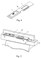
- FIGURE 4 is a perspective view of the graduated scale, the sensing graticule and the linear sensor of photodetectors of the optical measuring device of FIGURE 1.
- FIGURE 5 is a perspective view of part of the optical measuring device of FIGURE 1 in which the adhesive means fixing the support piece to the positioning module can be seen.
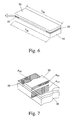
- FIGURE 6 is a first schematic view in perspective in which the positioning module, the adhesive means and the support piece of the optical measuring device of the invention are shown.
- FIGURE 7 is a second schematic view in perspective in which the positioning module, the adhesive means and the support piece of the optical measuring device of the invention are shown.
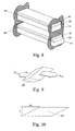
- FIGURE 8 is a schematic view in perspective of the positioning module, the adhesive means and the support piece in a first situation in which there is no expansion and in a second situation in which there is expansion.
- FIGURE 9 is a schematic view in perspective of the adhesive means and the forces that the positioning module and the support piece exert on said adhesive means.
- FIGURE 10 is a profile view of the adhesive means in FIGURE 9.
- With reference to figures 1 to 5, the optical measuring device 1 of the invention is of the type that comprises a glass graduated
scale 2 with an incremental track and an absolute track, and a detection unit. The detection unit comprises means for measuring a relative position which comprise afirst photoemitter 6, asensing graticule 7 and photodetector means 8, and means for measuring an absolute position which comprise asecond photoemitter 9 and a CCD-type linear sensor ofphotodetectors 11. - With reference to figure 1, the device 1 measures linear displacements and in the embodiment shown the graduated
scale 2 is attached to aprotective profile 3 that is itself attached to a first fixed object (not shown in the figures), for example, a bed. The detection unit comprises apositioning module 10 that incorporates the means for measuring the relative and absolute position. Thepositioning module 10 is attached to anattachment support 5 which is in turn attached to a second object (not shown in the figures), for example, a slide that is displaced in relation to a bed. - With reference to figure 2, the means for measuring the relative position and the means for measuring the absolute position are separated spatially in the direction of the relative displacement of the detection unit in relation to the graduated
scale 2. The detection unit comprises apositioning module 10 that comprises asupport piece 30 in which thesensing graticule 7 and the linear sensor ofphotodetectors 11 are arranged. Thesupport piece 30 is attached to thepositioning module 10 byadhesive means 20. - The
support piece 30 is of a different material to that of the graduatedscale 2, and the physical characteristics of thesupport piece 30, the adhesive means 20 and thepositioning module 10 are such that the equivalent thermal expansion coefficient α30e of thesupport piece 30 is substantially the same as the thermal expansion coefficient α2 of the graduatedscale 2. Logically, the thermal expansion coefficient α2 to be considered will be the thermal expansion coefficient that the graduatedscale 2 has when it is attached to theprotective profile 3, as the thermal expansion coefficient of the free graduatedscale 2 may be different to that of said graduatedscale 2 when it is attached to saidprotective profile 3. - Consider the set formed by the
positioning module 10, the adhesive means 20 and thesupport piece 30, represented in schematic mode in figures 6 and 7. Thepositioning module 10 has a cross section A10, a length L10, a modulus of elasticity E10 and a thermal expansion coefficient α10. The adhesive means 20 have a longitudinal section A20, a thickness t, a modulus of shearing G20 and a thermal expansion coefficient α20. Finally, thesupport piece 30 has a cross section A30, a length L30, a modulus of elasticity E30 and a thermal expansion coefficient α30. - In the embodiment of this example the
adhesive means 20 are arranged on the ends of thesupport piece 30 although saidadhesive means 20 can be arranged in another way, for example on the entire lower surface of thepositioning module 10 or forming lateral strips around saidpositioning module 10. - In reference conditions for the assembly of device 1 of the invention, at a reference temperature T0 (usually 20°C), when the
positioning module 10 is attached to thesupport piece 30 the adhesive means 20 are free of stresses. - Suppose that an increase in temperature occurs and the temperature T0 rises to another temperature T0+ΔT. As figure 8 shows, both the
positioning module 10 and thesupport piece 30 increase in length. However, said increase in length is not free, but is influenced by the elements to which they are attached, which means that each material is not governed by its corresponding expansion coefficient but by a "conditioned" expansion coefficient.
Due to the variation in temperature, the adhesive means 20 are deformed as shown in figure 9. For a situation of equilibrium, where F10 is the force that thepositioning module 10 exerts on the adhesive means 20 and where F30 is the force that thesupport piece 30 exerts on the adhesive means 20, it holds that: F 10 = -F30
- In analysing the status of the
positioning module 10, the following equation can be written:
- Said equation combines the effects of the change of length caused by the increase in temperature and the change of length to which it is subjected due to the force acting on it (Hooke's Law).
- Similarly, for the
support piece 30 it can be said that:
- In taking into consideration the state of deformation caused by the shearing that occurs in the adhesive means 20 and which is represented in figure 10, in using Hooke's Law regarding shearing stresses it can be said that:

- The expression that appears in the numerator on the right of the equation corresponds to the value m which is indicated in figure 10.
- Taking into consideration that the following values are known:
- A10
- Cross section of the
positioning module 10 - L10
- Length of the
positioning module 10 - E10
- Modulus of elasticity of the
positioning module 10 - α10
- Expansion coefficient of the
positioning module 10 - A20
- Longitudinal section of the adhesive means 20
- t
- Thickness of the adhesive means 20
- G20
- Modulus of shearing of the adhesive means 20
- α20
- Expansion coefficient of the adhesive means 20
- A30
- Cross section of the
support piece 30 - L30
- Length of the
support piece 30 - E30
- Modulus of elasticity of the
support piece 30 - α30
- Expansion coefficient of the
support piece 30 - ΔT
- Variation of temperature
- ΔL10
- Variation of the length of the
positioning module 10 - ΔL30
- Variation of the length of the
support piece 30 - F10
- Force exerted on the
positioning module 10 - F30
- Force exerted on the
support piece 30 - Given that there are four equations and four unknown variables, the system is determined, as a result of which the values of the unknown variables can be obtained.
- Equivalent expansion coefficients can be obtained from the following expressions:


- Thus, in selecting suitable values for the variables considered, the equivalent thermal expansion coefficient α30e of the
support piece 30 can be made equal to the thermal expansion coefficient α2 of the graduatedscale 2. It is noted that when selecting the values for the different variables there are a large number of different possibilities, and the materials and dimensions considered most suitable in each case can be selected (different material for thesupport piece 30 for example, modification of the dimensions of saidsupport piece 30, of the thickness of the adhesive means, etcetera). This means that various modification strategies could be initiated giving rise to a wide variety of options. - It can be seen, therefore, that when implementing the solution the effect of the tractions or compressions exerted by the
positioning module 10 and thesupport piece 30 is considered to be a component additional to the expansion or contraction caused by the change of temperature. In short, the variables affecting the expansion of thesupport piece 30 have been identified and a solution in which said variables are taken into consideration has been proposed.
A specific solution for this embodiment of the invention is shown below. In said specific solution the following values are selected for the physical characteristics of thepositioning module 10, the adhesive means 20 and the support piece 30:Positioning module 10 Reinforced ABSAdhesive means 20 Silicon type Support piece 30 Alumina (Al2O3) A10 50 · 10-6 [m2] A20 13 · 10-6 [m2] A 305 · 10-6 [m2] L10 46 · 10-3 [m] t 0.6 · 10-3 [m] L30 46 · 10-3 [m] E10 14.5 · 109 [Pa] G20 300 · 106 [Pa] E30 303 · 109 [Pa] α 1030 · 10-6 [m/(mK)] α20 67 · 10-6 [m/(mK)] α30 6.3 · 10-6 [m/(mK)] - In considering a difference of temperature of 10°C, the equations would be as follows:


- In solving the system of equations the following is obtained:
ΔL10=12.1·10-6 [m] ΔL30=3.7·10-6 [m] F10=-27.2 [N] F30=27.2 [N] - And based on these values the equivalent expansion coefficients α10e and α30e can be calculated using the following equations:


- From these the following is obtained:

- The value of the equivalent expansion coefficient α30e of the
support piece 30 is practically the same as that of the glass of the graduatedscale 2, as intended. This has been achieved by appropriately selecting materials and their dimensions. - In the embodiment shown schematically in figure 6, the adhesive means 20 are arranged on the ends of the
support piece 30 and said support means 20 have, on the two ends, the longitudinal section A20, the thickness t, the modulus of shearing G20, and the thermal expansion coefficient α20. However, in a second embodiment, different adhesives are used on each end. More specifically, a rigid adhesive is used on one end, i.e. an adhesive with a high modulus of shearing G, and a flexible adhesive is used on the other end, i.e. an adhesive with a low modulus of shearing G. The connection between the variables involved in this second embodiment can be obtained through calculations similar to those made for the first embodiment. - In this second embodiment, the adhesive means 20 on the end of the
support piece 30 closest to thepoint 40 at which the movement produced by the relative displacement is transmitted to thepositioning module 10 are rigid adhesive means, and the adhesive means 20 on the other end are flexible adhesive means. Saidpoint 40, shown in figure 5, is a ball through which the second object (usually a slide attached to a bed) transmits the translation movement to thepositioning module 10. As a result, thesupport piece 30 is attached to thepositioning module 10 by a rigid point (that corresponding to the rigid adhesive) and a flexible point (that corresponding to the flexible adhesive). By positioning the rigid point close to thepoint 40, which is a fixed reference point, the effects deriving from the expansion of thepositioning module 10 are minimised, as the further said rigid point is from thepoint 40, the further said rigid point will be displaced in relation to thepoint 40 for the same increase in temperature caused by the action of the expansion of thepositioning module 10. - In a preferred embodiment, the
support piece 30 has a high modulus of elasticity E30 and a thermal expansion coefficient α30 smaller than the thermal expansion coefficient α2 of the graduatedscale 2. This ensures that, in the event of an increase of temperature, the traction strains of the material of thepositioning module 10, which will have a much higher thermal expansion coefficient α10, cause thesupport piece 30 to stretch in such a way that the equivalent expansion of saidsupport piece 30 is the same as the expansion of the graduatedscale 2. To ensure this occurs, the cross section A30 of saidsupport piece 30 is not arbitrary, but must be selected so that the effect of the set is the required one. - More specifically, in a preferred embodiment the
support piece 30 is made of alumina, a material that effectively has a high modulus of elasticity E30 and a thermal expansion coefficient α30 smaller than the thermal expansion coefficient α2 of the graduatedscale 2. - As can be seen in figures 2 to 5, in the embodiment shown the
support piece 30 comprises a first cavity in which the CCD-type linear sensor ofphotodetectors 11 is housed and a second cavity in which thesensing graticule 7 is housed. Said linear sensor ofphotodetectors 11 and saidsensing graticule 7 are rigidly attached to thesupport piece 30. - It is also possible that the
sensing graticule 7, instead of being housed in a cavity formed in thesupport piece 30, is etched on thesupport piece 30 itself. - Although the invention refers in particular to optical measuring devices with a graduated scale, an incremental track and an absolute track, and with a detection unit with the means for measuring a relative position and an absolute position, its scope also includes any type of measuring device in which it is necessary to maintain a correspondence between the variation of the separation between two sensor elements due to the action of the expansion, and the expansion of a graduated scale.
Claims (10)
- Optical measuring device that comprises
a graduated scale (2) with an incremental track and an absolute track, and
a detection unit that comprises
means for measuring a relative position that comprise a first photoemitter (6), a sensing graticule (7) and photodetector means (8), and
means for measuring an absolute position that comprise a second photoemitter (9) and a linear sensor of photodetectors (11),
said means for measuring a relative position and said means for measuring an absolute position being separated spatially in the direction of the relative displacement of the detection unit in relation to the graduated scale (2), and
the detection unit comprising a positioning module (10) that comprises a support piece (30) in which the sensing graticule (7) and the linear sensor of photodetectors (11) are arranged, said support piece (30) being attached to the positioning module (10) by adhesive means (20),
characterised in that the support piece (30) is of a different material to that of the graduated scale (2) and
the physical characteristics of the support piece (30), the adhesive means (20) and the positioning module (10) are such that the equivalent thermal expansion coefficient (α30e) of the support piece (30) is substantially the same as the thermal expansion coefficient (α2) of the graduated scale (2). - Optical measuring device according to claim 1, wherein said physical characteristics are
the cross section (A10), the length (L10), the modulus of elasticity (E10) and the thermal expansion coefficient (α10) of the positioning module (10),
the longitudinal section (A20), the thickness (t), the modulus of shearing (G20), and the thermal expansion coefficient (α20) of the adhesive means (20), and
the cross section (A30), the length (L30), the modulus of elasticity (E30) and the thermal expansion coefficient (α30) of the support piece (30). - Optical measuring device according to claim 2, wherein the adhesive means (20) are arranged on the ends of the support piece (30).
- Optical measuring device according to claim 3, wherein the adhesive means (20) on the end of the support piece (30) closest to the point (40) at which the movement produced by the relative displacement is transmitted to the positioning module (10) are rigid adhesive means.
- Optical measuring device according to any of the preceding claims, wherein the support piece (30) has a high modulus of elasticity (E30) and a thermal expansion coefficient (α30) smaller than the thermal expansion coefficient (α2) of the graduated scale (2).
- Optical measuring device according to claim 5, wherein the support piece (30) is made of alumina.
- Optical measuring device according to any of the preceding claims, wherein the support piece (30) comprises a first cavity in which the linear sensor of photodetectors (11) is housed and a second cavity in which the sensing graticule (7) is housed.
- Optical measuring device according to any of claims 1 to 6, wherein the support piece (30) comprises a cavity in which the linear sensor of photodetectors (11) is housed and the sensing graticule (7) is etched on the support piece (30) itself.
- Positioning module for a detection unit of an optical measuring device (1),
the optical measuring device (1) comprising a graduated scale (2) with an incremental track and an absolute track,
the detection unit comprising
means for measuring a relative position that comprise a first photoemitter (6), a sensing graticule (7) and photodetector means (8), and
means for measuring an absolute position that comprise a second photoemitter (9) and a linear sensor of photodetectors (11), and
the positioning module (10) comprising a support piece (30) in which the sensing graticule (7) and the linear sensor of photodetectors (11) are arranged, said support piece (30) being attached to the positioning module (10) by adhesive means (20),
characterised in that the support piece (30) is of a different material to that of the graduated scale (2) and
the physical characteristics of the support piece (30), the adhesive means (20) and the positioning module (10) are such that the equivalent thermal expansion coefficient (α30e) of the support piece (30) is substantially the same as the thermal expansion coefficient (α2) of the graduated scale (2). - Positioning module according to claim 9, wherein said physical characteristics are
the cross section (A10), the length (L10), the modulus of elasticity (E10) and the thermal expansion coefficient (α10) of the positioning module (10),
the longitudinal section (A20), the thickness (t), the modulus of shearing (G20), and the thermal expansion coefficient (α20) of the adhesive means (20), and
the cross section (A30), the length (L30), the modulus of elasticity (E30) and the thermal expansion coefficient (α30) of the support piece (30).
Priority Applications (5)
| Application Number | Priority Date | Filing Date | Title |
|---|---|---|---|
| EP04380233A EP1659373B1 (en) | 2004-11-23 | 2004-11-23 | Linear encoder with temperature compensation |
| ES04380233T ES2285390T3 (en) | 2004-11-23 | 2004-11-23 | LINEAR ENCODER WITH TEMPERATURE COMPENSATION. |
| DE602004006877T DE602004006877T2 (en) | 2004-11-23 | 2004-11-23 | Linear position transmitter with temperature compensation |
| AT04380233T ATE364168T1 (en) | 2004-11-23 | 2004-11-23 | LINEAR POSITIONER WITH TEMPERATURE COMPENSATION |
| CN200510123348A CN100575886C (en) | 2004-11-23 | 2005-11-23 | Optical measuring device with temperature compensation |
Applications Claiming Priority (1)
| Application Number | Priority Date | Filing Date | Title |
|---|---|---|---|
| EP04380233A EP1659373B1 (en) | 2004-11-23 | 2004-11-23 | Linear encoder with temperature compensation |
Publications (2)
| Publication Number | Publication Date |
|---|---|
| EP1659373A1 true EP1659373A1 (en) | 2006-05-24 |
| EP1659373B1 EP1659373B1 (en) | 2007-06-06 |
Family
ID=34931874
Family Applications (1)
| Application Number | Title | Priority Date | Filing Date |
|---|---|---|---|
| EP04380233A Active EP1659373B1 (en) | 2004-11-23 | 2004-11-23 | Linear encoder with temperature compensation |
Country Status (5)
| Country | Link |
|---|---|
| EP (1) | EP1659373B1 (en) |
| CN (1) | CN100575886C (en) |
| AT (1) | ATE364168T1 (en) |
| DE (1) | DE602004006877T2 (en) |
| ES (1) | ES2285390T3 (en) |
Cited By (4)
| Publication number | Priority date | Publication date | Assignee | Title |
|---|---|---|---|---|
| EP1882989A2 (en) * | 2006-07-27 | 2008-01-30 | Ricoh Company, Ltd. | Position detecting device and image forming apparatus |
| FR2974897A1 (en) * | 2011-05-02 | 2012-11-09 | Symetrie | Linear device for measuring distance and/or displacement in hexapod type system, has interface part connecting position coding element and another fixing interface to maintain distance between coding element and fixing interface |
| EP2908098A1 (en) * | 2014-02-18 | 2015-08-19 | Hexagon Technology Center GmbH | Linear encoder with calibrating functionality |
| WO2024033621A1 (en) * | 2022-08-09 | 2024-02-15 | Renishaw Plc | Scale |
Families Citing this family (3)
| Publication number | Priority date | Publication date | Assignee | Title |
|---|---|---|---|---|
| ATE533034T1 (en) * | 2010-03-18 | 2011-11-15 | Fagor S Coop | OPTOELECTRONIC MEASURING DEVICE |
| EP2636991A1 (en) * | 2012-03-07 | 2013-09-11 | Hexagon Metrology S.p.A. | Measuring machine with compensation system for errors due to the thermal deformation of a scale of a linear transducer |
| CN114721098B (en) * | 2022-02-22 | 2024-01-30 | 中国电子科技集团公司第十三研究所 | Photoelectric coupling device and manufacturing method thereof |
Citations (2)
| Publication number | Priority date | Publication date | Assignee | Title |
|---|---|---|---|---|
| US4815213A (en) * | 1987-10-09 | 1989-03-28 | Brown & Sharpe Manufacturing Co. | Apparatus for temperature compensation of sensing means of a machine |
| US5182867A (en) * | 1991-05-11 | 1993-02-02 | Dr. Johannes Heidenhain Gmbh | Position measuring apparatus |
Family Cites Families (3)
| Publication number | Priority date | Publication date | Assignee | Title |
|---|---|---|---|---|
| CH683798A5 (en) * | 1990-12-10 | 1994-05-13 | Tesa Sa | position sensor for an apparatus for measuring linear or angular variables. |
| DE19919042A1 (en) * | 1999-04-27 | 2000-11-02 | Heidenhain Gmbh Dr Johannes | Thermally compensated measurement system has evaluation unit that computes temperature from relative motion of scale at 2 sensing points, compensates measurements for thermal effects |
| DE10132521A1 (en) * | 2001-07-09 | 2003-01-30 | Heidenhain Gmbh Dr Johannes | Position measuring device |
-
2004
- 2004-11-23 ES ES04380233T patent/ES2285390T3/en active Active
- 2004-11-23 EP EP04380233A patent/EP1659373B1/en active Active
- 2004-11-23 AT AT04380233T patent/ATE364168T1/en not_active IP Right Cessation
- 2004-11-23 DE DE602004006877T patent/DE602004006877T2/en active Active
-
2005
- 2005-11-23 CN CN200510123348A patent/CN100575886C/en not_active Expired - Fee Related
Patent Citations (2)
| Publication number | Priority date | Publication date | Assignee | Title |
|---|---|---|---|---|
| US4815213A (en) * | 1987-10-09 | 1989-03-28 | Brown & Sharpe Manufacturing Co. | Apparatus for temperature compensation of sensing means of a machine |
| US5182867A (en) * | 1991-05-11 | 1993-02-02 | Dr. Johannes Heidenhain Gmbh | Position measuring apparatus |
Cited By (8)
| Publication number | Priority date | Publication date | Assignee | Title |
|---|---|---|---|---|
| EP1882989A2 (en) * | 2006-07-27 | 2008-01-30 | Ricoh Company, Ltd. | Position detecting device and image forming apparatus |
| EP1882989A3 (en) * | 2006-07-27 | 2008-02-27 | Ricoh Company, Ltd. | Position detecting device and image forming apparatus |
| JP2008051801A (en) * | 2006-07-27 | 2008-03-06 | Ricoh Co Ltd | Position detecting device and image forming apparatus |
| US7840163B2 (en) | 2006-07-27 | 2010-11-23 | Ricoh Company, Ltd. | Position detecting device and image forming apparatus |
| FR2974897A1 (en) * | 2011-05-02 | 2012-11-09 | Symetrie | Linear device for measuring distance and/or displacement in hexapod type system, has interface part connecting position coding element and another fixing interface to maintain distance between coding element and fixing interface |
| EP2908098A1 (en) * | 2014-02-18 | 2015-08-19 | Hexagon Technology Center GmbH | Linear encoder with calibrating functionality |
| US9846063B2 (en) | 2014-02-18 | 2017-12-19 | Hexagon Technology Center Gmbh | Linear encoder having calibration functionality |
| WO2024033621A1 (en) * | 2022-08-09 | 2024-02-15 | Renishaw Plc | Scale |
Also Published As
| Publication number | Publication date |
|---|---|
| CN1779419A (en) | 2006-05-31 |
| ES2285390T3 (en) | 2007-11-16 |
| DE602004006877D1 (en) | 2007-07-19 |
| ATE364168T1 (en) | 2007-06-15 |
| CN100575886C (en) | 2009-12-30 |
| EP1659373B1 (en) | 2007-06-06 |
| DE602004006877T2 (en) | 2008-02-07 |
Similar Documents
| Publication | Publication Date | Title |
|---|---|---|
| KR100984378B1 (en) | Vehicle weight measuring apparatus | |
| JP6650725B2 (en) | Length measuring device | |
| US20160220319A1 (en) | Force/torque transducer and method of operating the same | |
| EP1659373B1 (en) | Linear encoder with temperature compensation | |
| US20060137204A1 (en) | Linear moving capacitive sensor twin column electronic height gauge | |
| PT2064532E (en) | System for detecting the pressure in a vehicle tyre and/or speed of the vehicle | |
| EA004197B1 (en) | Tensile testing sensor for measuring mechanical jamming deformations on first installation and automatic calibrating based on said jamming | |
| EP0498780B1 (en) | A method and arrangement for determining the linear (heat) expansion of elongated bodies | |
| ATE143133T1 (en) | MEASURING WHEEL SET FOR RAIL VEHICLES | |
| US20160153828A1 (en) | Force sensor device for detecting the weight of a vehicle | |
| EP3333555A1 (en) | Structural arrangement for weigh in motion systems | |
| US11519763B2 (en) | Assembly including a main support, an intermediate support disposed on the main support, and a scale disposed on the intermediate support | |
| US20210041312A1 (en) | Force sensor and sensing element thereof | |
| EP2636991A1 (en) | Measuring machine with compensation system for errors due to the thermal deformation of a scale of a linear transducer | |
| US10041856B2 (en) | Method and apparatus for measuring physical displacement | |
| CZ2015639A3 (en) | A device for measurement and a method of measurement | |
| US20030115968A1 (en) | Capacitive microsystem for recording mechanical deformations, use and operating method | |
| CN109029665B (en) | Pillow type rail Heng Chenchong sensor | |
| US7024789B2 (en) | Position measuring device with a temperature correction device | |
| JP4359165B2 (en) | Axial stress measuring device for laying rail | |
| JPH045921B2 (en) | ||
| US11733019B2 (en) | Assembly for position measurement | |
| HUT56621A (en) | Device for checking distance between endsurfaces of rails for example at expansion joints | |
| GB2194065A (en) | Weight sensing apparatus | |
| JPH0244367B2 (en) |
Legal Events
| Date | Code | Title | Description |
|---|---|---|---|
| PUAI | Public reference made under article 153(3) epc to a published international application that has entered the european phase |
Free format text: ORIGINAL CODE: 0009012 |
|
| AK | Designated contracting states |
Kind code of ref document: A1 Designated state(s): AT BE BG CH CY CZ DE DK EE ES FI FR GB GR HU IE IS IT LI LU MC NL PL PT RO SE SI SK TR |
|
| AX | Request for extension of the european patent |
Extension state: AL HR LT LV MK YU |
|
| 17P | Request for examination filed |
Effective date: 20060704 |
|
| 17Q | First examination report despatched |
Effective date: 20061109 |
|
| AKX | Designation fees paid |
Designated state(s): AT BE BG CH CY CZ DE DK EE ES FI FR GB GR HU IE IS IT LI LU MC NL PL PT RO SE SI SK TR |
|
| GRAP | Despatch of communication of intention to grant a patent |
Free format text: ORIGINAL CODE: EPIDOSNIGR1 |
|
| GRAS | Grant fee paid |
Free format text: ORIGINAL CODE: EPIDOSNIGR3 |
|
| GRAA | (expected) grant |
Free format text: ORIGINAL CODE: 0009210 |
|
| AK | Designated contracting states |
Kind code of ref document: B1 Designated state(s): AT BE BG CH CY CZ DE DK EE ES FI FR GB GR HU IE IS IT LI LU MC NL PL PT RO SE SI SK TR |
|
| PG25 | Lapsed in a contracting state [announced via postgrant information from national office to epo] |
Ref country code: CH Free format text: LAPSE BECAUSE OF FAILURE TO SUBMIT A TRANSLATION OF THE DESCRIPTION OR TO PAY THE FEE WITHIN THE PRESCRIBED TIME-LIMIT Effective date: 20070606 Ref country code: FI Free format text: LAPSE BECAUSE OF FAILURE TO SUBMIT A TRANSLATION OF THE DESCRIPTION OR TO PAY THE FEE WITHIN THE PRESCRIBED TIME-LIMIT Effective date: 20070606 Ref country code: LI Free format text: LAPSE BECAUSE OF FAILURE TO SUBMIT A TRANSLATION OF THE DESCRIPTION OR TO PAY THE FEE WITHIN THE PRESCRIBED TIME-LIMIT Effective date: 20070606 |
|
| REG | Reference to a national code |
Ref country code: GB Ref legal event code: FG4D |
|
| REG | Reference to a national code |
Ref country code: CH Ref legal event code: EP |
|
| REG | Reference to a national code |
Ref country code: IE Ref legal event code: FG4D |
|
| REF | Corresponds to: |
Ref document number: 602004006877 Country of ref document: DE Date of ref document: 20070719 Kind code of ref document: P |
|
| PG25 | Lapsed in a contracting state [announced via postgrant information from national office to epo] |
Ref country code: SE Free format text: LAPSE BECAUSE OF FAILURE TO SUBMIT A TRANSLATION OF THE DESCRIPTION OR TO PAY THE FEE WITHIN THE PRESCRIBED TIME-LIMIT Effective date: 20070906 |
|
| REG | Reference to a national code |
Ref country code: ES Ref legal event code: FG2A Ref document number: 2285390 Country of ref document: ES Kind code of ref document: T3 |
|
| PG25 | Lapsed in a contracting state [announced via postgrant information from national office to epo] |
Ref country code: AT Free format text: LAPSE BECAUSE OF FAILURE TO SUBMIT A TRANSLATION OF THE DESCRIPTION OR TO PAY THE FEE WITHIN THE PRESCRIBED TIME-LIMIT Effective date: 20070606 Ref country code: PL Free format text: LAPSE BECAUSE OF FAILURE TO SUBMIT A TRANSLATION OF THE DESCRIPTION OR TO PAY THE FEE WITHIN THE PRESCRIBED TIME-LIMIT Effective date: 20070606 |
|
| NLV1 | Nl: lapsed or annulled due to failure to fulfill the requirements of art. 29p and 29m of the patents act | ||
| REG | Reference to a national code |
Ref country code: CH Ref legal event code: PL |
|
| PG25 | Lapsed in a contracting state [announced via postgrant information from national office to epo] |
Ref country code: BE Free format text: LAPSE BECAUSE OF FAILURE TO SUBMIT A TRANSLATION OF THE DESCRIPTION OR TO PAY THE FEE WITHIN THE PRESCRIBED TIME-LIMIT Effective date: 20070606 |
|
| PG25 | Lapsed in a contracting state [announced via postgrant information from national office to epo] |
Ref country code: PT Free format text: LAPSE BECAUSE OF FAILURE TO SUBMIT A TRANSLATION OF THE DESCRIPTION OR TO PAY THE FEE WITHIN THE PRESCRIBED TIME-LIMIT Effective date: 20071106 Ref country code: BG Free format text: LAPSE BECAUSE OF FAILURE TO SUBMIT A TRANSLATION OF THE DESCRIPTION OR TO PAY THE FEE WITHIN THE PRESCRIBED TIME-LIMIT Effective date: 20070906 Ref country code: IS Free format text: LAPSE BECAUSE OF FAILURE TO SUBMIT A TRANSLATION OF THE DESCRIPTION OR TO PAY THE FEE WITHIN THE PRESCRIBED TIME-LIMIT Effective date: 20071006 Ref country code: CZ Free format text: LAPSE BECAUSE OF FAILURE TO SUBMIT A TRANSLATION OF THE DESCRIPTION OR TO PAY THE FEE WITHIN THE PRESCRIBED TIME-LIMIT Effective date: 20070606 Ref country code: SI Free format text: LAPSE BECAUSE OF FAILURE TO SUBMIT A TRANSLATION OF THE DESCRIPTION OR TO PAY THE FEE WITHIN THE PRESCRIBED TIME-LIMIT Effective date: 20070606 Ref country code: NL Free format text: LAPSE BECAUSE OF FAILURE TO SUBMIT A TRANSLATION OF THE DESCRIPTION OR TO PAY THE FEE WITHIN THE PRESCRIBED TIME-LIMIT Effective date: 20070606 |
|
| EN | Fr: translation not filed | ||
| PG25 | Lapsed in a contracting state [announced via postgrant information from national office to epo] |
Ref country code: SK Free format text: LAPSE BECAUSE OF FAILURE TO SUBMIT A TRANSLATION OF THE DESCRIPTION OR TO PAY THE FEE WITHIN THE PRESCRIBED TIME-LIMIT Effective date: 20070606 |
|
| PLBE | No opposition filed within time limit |
Free format text: ORIGINAL CODE: 0009261 |
|
| STAA | Information on the status of an ep patent application or granted ep patent |
Free format text: STATUS: NO OPPOSITION FILED WITHIN TIME LIMIT |
|
| PG25 | Lapsed in a contracting state [announced via postgrant information from national office to epo] |
Ref country code: DK Free format text: LAPSE BECAUSE OF FAILURE TO SUBMIT A TRANSLATION OF THE DESCRIPTION OR TO PAY THE FEE WITHIN THE PRESCRIBED TIME-LIMIT Effective date: 20070606 Ref country code: GR Free format text: LAPSE BECAUSE OF FAILURE TO SUBMIT A TRANSLATION OF THE DESCRIPTION OR TO PAY THE FEE WITHIN THE PRESCRIBED TIME-LIMIT Effective date: 20070907 |
|
| 26N | No opposition filed |
Effective date: 20080307 |
|
| PG25 | Lapsed in a contracting state [announced via postgrant information from national office to epo] |
Ref country code: RO Free format text: LAPSE BECAUSE OF FAILURE TO SUBMIT A TRANSLATION OF THE DESCRIPTION OR TO PAY THE FEE WITHIN THE PRESCRIBED TIME-LIMIT Effective date: 20070606 |
|
| PG25 | Lapsed in a contracting state [announced via postgrant information from national office to epo] |
Ref country code: MC Free format text: LAPSE BECAUSE OF NON-PAYMENT OF DUE FEES Effective date: 20071130 |
|
| PG25 | Lapsed in a contracting state [announced via postgrant information from national office to epo] |
Ref country code: FR Free format text: LAPSE BECAUSE OF FAILURE TO SUBMIT A TRANSLATION OF THE DESCRIPTION OR TO PAY THE FEE WITHIN THE PRESCRIBED TIME-LIMIT Effective date: 20080201 |
|
| PG25 | Lapsed in a contracting state [announced via postgrant information from national office to epo] |
Ref country code: IE Free format text: LAPSE BECAUSE OF NON-PAYMENT OF DUE FEES Effective date: 20071123 |
|
| PG25 | Lapsed in a contracting state [announced via postgrant information from national office to epo] |
Ref country code: EE Free format text: LAPSE BECAUSE OF FAILURE TO SUBMIT A TRANSLATION OF THE DESCRIPTION OR TO PAY THE FEE WITHIN THE PRESCRIBED TIME-LIMIT Effective date: 20070606 |
|
| GBPC | Gb: european patent ceased through non-payment of renewal fee |
Effective date: 20081123 |
|
| PG25 | Lapsed in a contracting state [announced via postgrant information from national office to epo] |
Ref country code: CY Free format text: LAPSE BECAUSE OF FAILURE TO SUBMIT A TRANSLATION OF THE DESCRIPTION OR TO PAY THE FEE WITHIN THE PRESCRIBED TIME-LIMIT Effective date: 20070606 |
|
| PG25 | Lapsed in a contracting state [announced via postgrant information from national office to epo] |
Ref country code: LU Free format text: LAPSE BECAUSE OF NON-PAYMENT OF DUE FEES Effective date: 20071123 |
|
| PG25 | Lapsed in a contracting state [announced via postgrant information from national office to epo] |
Ref country code: TR Free format text: LAPSE BECAUSE OF FAILURE TO SUBMIT A TRANSLATION OF THE DESCRIPTION OR TO PAY THE FEE WITHIN THE PRESCRIBED TIME-LIMIT Effective date: 20070606 Ref country code: HU Free format text: LAPSE BECAUSE OF FAILURE TO SUBMIT A TRANSLATION OF THE DESCRIPTION OR TO PAY THE FEE WITHIN THE PRESCRIBED TIME-LIMIT Effective date: 20071207 |
|
| PG25 | Lapsed in a contracting state [announced via postgrant information from national office to epo] |
Ref country code: GB Free format text: LAPSE BECAUSE OF NON-PAYMENT OF DUE FEES Effective date: 20081123 |
|
| PGFP | Annual fee paid to national office [announced via postgrant information from national office to epo] |
Ref country code: IT Payment date: 20071130 Year of fee payment: 4 |
|
| PGFP | Annual fee paid to national office [announced via postgrant information from national office to epo] |
Ref country code: DE Payment date: 20121121 Year of fee payment: 9 |
|
| PGFP | Annual fee paid to national office [announced via postgrant information from national office to epo] |
Ref country code: ES Payment date: 20121119 Year of fee payment: 9 |
|
| REG | Reference to a national code |
Ref country code: DE Ref legal event code: R119 Ref document number: 602004006877 Country of ref document: DE Effective date: 20140603 |
|
| PG25 | Lapsed in a contracting state [announced via postgrant information from national office to epo] |
Ref country code: DE Free format text: LAPSE BECAUSE OF NON-PAYMENT OF DUE FEES Effective date: 20140603 |
|
| REG | Reference to a national code |
Ref country code: ES Ref legal event code: FD2A Effective date: 20150327 |
|
| PG25 | Lapsed in a contracting state [announced via postgrant information from national office to epo] |
Ref country code: ES Free format text: LAPSE BECAUSE OF NON-PAYMENT OF DUE FEES Effective date: 20131124 |