CN113474634A - Sensor device - Google Patents
Sensor device Download PDFInfo
- Publication number
- CN113474634A CN113474634A CN202080015682.7A CN202080015682A CN113474634A CN 113474634 A CN113474634 A CN 113474634A CN 202080015682 A CN202080015682 A CN 202080015682A CN 113474634 A CN113474634 A CN 113474634A
- Authority
- CN
- China
- Prior art keywords
- distal end
- cover
- end surface
- hole
- sensor
- Prior art date
- Legal status (The legal status is an assumption and is not a legal conclusion. Google has not performed a legal analysis and makes no representation as to the accuracy of the status listed.)
- Withdrawn
Links
- 238000001514 detection method Methods 0.000 claims abstract description 72
- 230000002093 peripheral effect Effects 0.000 claims abstract description 40
- 239000013618 particulate matter Substances 0.000 claims description 12
- 238000002485 combustion reaction Methods 0.000 claims description 9
- 230000007423 decrease Effects 0.000 claims description 5
- 239000007789 gas Substances 0.000 description 112
- XLYOFNOQVPJJNP-UHFFFAOYSA-N water Substances O XLYOFNOQVPJJNP-UHFFFAOYSA-N 0.000 description 51
- 230000000694 effects Effects 0.000 description 12
- 230000000717 retained effect Effects 0.000 description 8
- 230000035945 sensitivity Effects 0.000 description 7
- 238000009833 condensation Methods 0.000 description 5
- 230000005494 condensation Effects 0.000 description 5
- 238000000746 purification Methods 0.000 description 5
- 230000000052 comparative effect Effects 0.000 description 4
- 238000010586 diagram Methods 0.000 description 4
- 239000010410 layer Substances 0.000 description 4
- QVGXLLKOCUKJST-UHFFFAOYSA-N atomic oxygen Chemical compound [O] QVGXLLKOCUKJST-UHFFFAOYSA-N 0.000 description 3
- 238000011109 contamination Methods 0.000 description 3
- 238000005336 cracking Methods 0.000 description 3
- 230000014759 maintenance of location Effects 0.000 description 3
- 239000001301 oxygen Substances 0.000 description 3
- 229910052760 oxygen Inorganic materials 0.000 description 3
- 238000010186 staining Methods 0.000 description 3
- 238000009736 wetting Methods 0.000 description 3
- 230000005856 abnormality Effects 0.000 description 2
- 239000003054 catalyst Substances 0.000 description 2
- 239000000446 fuel Substances 0.000 description 2
- 238000009434 installation Methods 0.000 description 2
- 239000000758 substrate Substances 0.000 description 2
- 238000011144 upstream manufacturing Methods 0.000 description 2
- 244000126211 Hericium coralloides Species 0.000 description 1
- PNEYBMLMFCGWSK-UHFFFAOYSA-N aluminium oxide Inorganic materials [O-2].[O-2].[O-2].[Al+3].[Al+3] PNEYBMLMFCGWSK-UHFFFAOYSA-N 0.000 description 1
- 229910010293 ceramic material Inorganic materials 0.000 description 1
- 239000004020 conductor Substances 0.000 description 1
- 239000000470 constituent Substances 0.000 description 1
- 238000003745 diagnosis Methods 0.000 description 1
- 238000007599 discharging Methods 0.000 description 1
- 238000010438 heat treatment Methods 0.000 description 1
- 239000007788 liquid Substances 0.000 description 1
- 238000004519 manufacturing process Methods 0.000 description 1
- 239000000463 material Substances 0.000 description 1
- 229910052751 metal Inorganic materials 0.000 description 1
- 239000002184 metal Substances 0.000 description 1
- 229910000510 noble metal Inorganic materials 0.000 description 1
- 230000001737 promoting effect Effects 0.000 description 1
- 230000004043 responsiveness Effects 0.000 description 1
- 239000002356 single layer Substances 0.000 description 1
- 238000005245 sintering Methods 0.000 description 1
- 238000001179 sorption measurement Methods 0.000 description 1
- 230000001629 suppression Effects 0.000 description 1
Images


Classifications
-
- G—PHYSICS
- G01—MEASURING; TESTING
- G01N—INVESTIGATING OR ANALYSING MATERIALS BY DETERMINING THEIR CHEMICAL OR PHYSICAL PROPERTIES
- G01N15/00—Investigating characteristics of particles; Investigating permeability, pore-volume, or surface-area of porous materials
- G01N15/06—Investigating concentration of particle suspensions
- G01N15/0656—Investigating concentration of particle suspensions using electric, e.g. electrostatic methods or magnetic methods
-
- G—PHYSICS
- G01—MEASURING; TESTING
- G01M—TESTING STATIC OR DYNAMIC BALANCE OF MACHINES OR STRUCTURES; TESTING OF STRUCTURES OR APPARATUS, NOT OTHERWISE PROVIDED FOR
- G01M15/00—Testing of engines
- G01M15/04—Testing internal-combustion engines
- G01M15/10—Testing internal-combustion engines by monitoring exhaust gases or combustion flame
- G01M15/102—Testing internal-combustion engines by monitoring exhaust gases or combustion flame by monitoring exhaust gases
-
- G—PHYSICS
- G01—MEASURING; TESTING
- G01N—INVESTIGATING OR ANALYSING MATERIALS BY DETERMINING THEIR CHEMICAL OR PHYSICAL PROPERTIES
- G01N15/00—Investigating characteristics of particles; Investigating permeability, pore-volume, or surface-area of porous materials
- G01N15/06—Investigating concentration of particle suspensions
- G01N15/0606—Investigating concentration of particle suspensions by collecting particles on a support
-
- G—PHYSICS
- G01—MEASURING; TESTING
- G01N—INVESTIGATING OR ANALYSING MATERIALS BY DETERMINING THEIR CHEMICAL OR PHYSICAL PROPERTIES
- G01N27/00—Investigating or analysing materials by the use of electric, electrochemical, or magnetic means
- G01N27/26—Investigating or analysing materials by the use of electric, electrochemical, or magnetic means by investigating electrochemical variables; by using electrolysis or electrophoresis
- G01N27/403—Cells and electrode assemblies
- G01N27/406—Cells and probes with solid electrolytes
- G01N27/407—Cells and probes with solid electrolytes for investigating or analysing gases
- G01N27/4077—Means for protecting the electrolyte or the electrodes
-
- G—PHYSICS
- G01—MEASURING; TESTING
- G01N—INVESTIGATING OR ANALYSING MATERIALS BY DETERMINING THEIR CHEMICAL OR PHYSICAL PROPERTIES
- G01N15/00—Investigating characteristics of particles; Investigating permeability, pore-volume, or surface-area of porous materials
- G01N2015/0042—Investigating dispersion of solids
- G01N2015/0046—Investigating dispersion of solids in gas, e.g. smoke
Abstract
A sensor device (S) is provided with: a housing (H) that holds the sensor element (2) so that the detection unit (21) is positioned on the distal end side in the axial direction (X) by inserting the sensor element inside; and an element cover (1) that is coaxially arranged on the distal end side of the housing, wherein a plurality of outer distal end surface holes (12b) are provided on the distal end surface (122) of the outer cover (12) at positions that are outside positions that face the outer peripheral edges of the inner distal end surface holes (11b), a central portion (122a) of the distal end surface (122) protrudes toward the inner distal end surface holes (11b), an outer peripheral portion (122b) of the outer distal end surface holes (12b) is arranged further toward the distal end side than the central portion (122a), and an inclined surface (123) that connects the central portion (122a) and the outer distal end surface holes (12b) is provided.
Description
Cross reference to related applications
The present application is based on japanese patent application No. 2019-029816, filed on 21/2/2019, the contents of which are incorporated herein by reference.
Technical Field
The present disclosure relates to a sensor device for detecting a specific component contained in a gas to be measured.
Background
An exhaust gas purification system including a sensor device for detecting a specific component in exhaust gas, and a purification device such as a filter device or a catalyst device is provided in an exhaust passage of an internal combustion engine. The sensor device is, for example, a PM sensor for detecting a Particulate Matter (hereinafter, referred to as PM as appropriate), and is disposed at a position downstream of the filter device for collecting PM to determine a filter failure. Further, an exhaust gas sensor such as an oxygen sensor is disposed upstream or downstream of the catalyst device.
The sensor body of such a sensor device generally includes a sensor element housed in a case and an element cover surrounding the outer periphery of the sensor element protruding from the case. The sensor element includes a detection portion at a distal end portion (end portion on the protruding side) protected by the element cover, and detects a specific component contained in the exhaust gas taken into the element cover. The element cover is usually formed in the shape of a single-layer or double-layer container.
For example, in the gas sensor described in patent document 1, the element cover has a double-layer cover structure, and includes an inner cover and an outer cover disposed outside the inner cover in a spaced manner. The exhaust gas flows into the space between the two covers through the gas flow holes opened in the side surfaces of the outer covers, and is introduced into the inside through the gas flow holes opened in the side surfaces of the inner covers. The exhaust gas that has contacted the sensor element in the inner cover flows to a gas flow hole that opens at the top end face of the inner cover, and merges with the gas flowing out to the outside.
Documents of the prior art
Patent document
Patent document 1: japanese patent laid-open publication No. 2018-180002
Disclosure of Invention
Further, if the temperature in the exhaust gas passage drops when the engine is stopped, moisture contained in the exhaust gas condenses, and condensed water is likely to be generated. The gas sensor described in patent document 1 has an element cover structure in which gas flow holes are not disposed at positions facing the distal end surfaces of the inner cover and the outer cover, and intrusion of condensed water from the outside can be suppressed. The inner cover has a shape having a reduced diameter step portion on the distal end side thereof, and condensed water contained in the exhaust gas flowing through the inner flow-through hole collides with the reduced diameter step portion to separate the condensed water from the exhaust gas, thereby suppressing the intrusion of the condensed water into the inner cover.
On the other hand, in recent years, vehicles equipped with an idle stop mechanism have increased, and it has been found that if the exhaust gas temperature sharply drops due to engine stop at idle, condensation also occurs in the element cover of the sensor. If condensed water produced by condensation in the cover is retained, the condensed water is swirled up as the exhaust gas flowing into the element cover flows at the time of engine start, and easily reaches the gas flow hole in the side surface of the inner cover. In this case, condensed water enters the inner cover and adheres to the sensor element, which may cause element cracking due to water contamination (hereinafter, referred to as water contamination cracking as appropriate).
Further, if the flow rate of exhaust gas inside the element cover becomes lower, the turn-up of condensed water is also suppressed, but in order to improve the detection performance of particulate matter and the like by the sensor element, it is desirable to increase the flow rate of exhaust gas to allow exhaust gas to reach the sensor element quickly.
Therefore, in general, many conventional element covers have a structure in which the distal end surface of the inner cover and the distal end surface of the outer cover are integrally provided to facilitate gas exchange. In this case, the gas flow hole is directly opened to the outside, and in reality, no measures are taken for the contamination resistance.
An object of the present disclosure is to provide a sensor device having a two-layer structure in which a sensor element is housed in an element case, which can suppress water-staining cracking of the sensor element to improve water-staining resistance and improve detection performance to improve reliability.
One aspect of the present disclosure is a sensor device including:
a sensor element including a detection unit for detecting a specific component in a gas to be measured;
a housing that holds the sensor element so that the detection portion is positioned on a distal end side in an axial direction by being inserted inside; and
an element cover coaxially disposed on the top end side of the housing,
the element cover has an inner cover disposed to cover a tip end side of the sensor element and an outer cover disposed to have a space outside the inner cover,
the inner cover is provided with an inner side surface hole and an inner top surface hole on the side surface and the top end surface respectively for the circulation of the gas to be measured,
the outer cover is provided with a plurality of outer side holes on the side surface through which the gas to be measured flows, and the top end positions of the outer side holes are closer to the top end side than the top end position of the inner cover,
a plurality of outer distal surface holes are provided in the distal surface of the outer cover at positions outside positions facing the outer peripheral edges of the inner distal surface holes,
the outer peripheral portion of the outer tip surface hole is disposed further toward the tip end side than the central portion, and has an inclined surface connecting the central portion and the outer tip surface hole.
According to the above configuration, even if condensed water is generated by condensation in the element cover during non-operation of the sensor device and the condensed water falls from the surface of the inner cover to the distal end surface of the outer cover due to its own weight, the condensed water is prevented from being accumulated because the central portion of the distal end surface is protruded. The condensed water moves more quickly from the center of the distal end surface along the inclined surface to the outer peripheral portion on the distal end side, and is quickly discharged to the outside from a plurality of outer distal end surface holes provided in the outer peripheral portion.
Therefore, even if the gas to be measured is introduced into the element cover during operation of the sensor device, the retained water is not rolled up, and the sensor element is prevented from being wetted by the water entering the inner cover.
In the element cover, the distal end position of the outer surface hole is located on the distal end side of the distal end position of the inner cover, and the flow of the gas to be measured introduced from the outer surface hole in the direction orthogonal to the axial direction generates a negative pressure in the vicinity of the inner distal end surface hole. By the suction effect due to this negative pressure, a flow flowing out from the inner tip surface hole to the housing is formed, thereby promoting the flow to the sensor element and improving the detection performance.
As described above, according to the above aspect, it is possible to provide a sensor device having excellent reliability by suppressing the occurrence of the water break of the sensor element and improving the water resistance and improving the detection performance in the structure in which the sensor element is housed in the element case having the two-layer structure.
Drawings
The above and other objects, features and advantages of the present disclosure will become more apparent from the following detailed description with reference to the accompanying drawings. In the context of this figure, it is shown,
fig. 1 is an enlarged cross-sectional view of a major part in the axial direction of a PM sensor in embodiment 1,
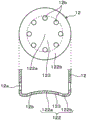
FIG. 2 is a plan view and an axial sectional view showing the shape of the tip end face of an element cover of a PM sensor according to embodiment 1,
FIG. 3 is an axial sectional view showing a schematic configuration of a PM sensor according to embodiment 1,
fig. 4 is a radial sectional view for explaining the flow of gas in the element cover of the PM sensor according to embodiment 1, and is a sectional view taken along line IV-IV of fig. 3,
FIG. 5 is a diagram showing a schematic configuration example of an exhaust gas purification system including a PM sensor according to embodiment 1,
fig. 6 is an overall perspective view of a sensor element of the PM sensor in embodiment 1,
FIG. 7 is an axial sectional view showing the state of retention and turn-up due to gas flow of condensed water in the element cover of the PM sensor in comparative example 1,
FIG. 8 is an axial sectional view showing the effect of the shape of the element cover based on the PM sensor in embodiment 1 in comparison with the shape of the conventional element cover,
FIG. 9 is a diagram showing the PM detection characteristics of the PM sensor in comparative example 1 and a main sectional view in the axial direction showing the influence of the retained water on the PM detection,
FIG. 10 is a graph showing the relationship between the output rise time and the detection current in the PM detection by the PM sensor according to embodiment 1,
FIG. 11 is a top end face shape of an element cover of the PM sensor in test example 1 and a sectional view taken along line A-A thereof,
fig. 12 is an enlarged cross-sectional view of a major part in the axial direction of the PM sensor in embodiment 2,
fig. 13 is a plan view and an axial sectional view showing another example of the shape of the distal end surface of the element cover of the PM sensor according to embodiment 2.
Detailed Description
(embodiment mode 1)
Hereinafter, embodiment 1 of the sensor device will be described with reference to the drawings.
As shown in fig. 1 to 4, the sensor device in the present embodiment is a PM sensor S for detecting particulate matter, and is applied to, for example, an exhaust gas purification device of an internal combustion engine E shown in fig. 5. In fig. 1, the PM sensor S includes: a sensor element 2 provided with a detection unit 21; a housing H that holds the sensor element 2 so that the detection unit 21 is positioned on the distal end side in the axial direction X by inserting the sensor element inside; and an element cover 1 coaxially disposed on the distal end side of the housing H.
The internal combustion engine E is, for example, an automotive diesel engine or a gasoline engine, and the detection unit 21 of the sensor element 2 detects particulate matter as a specific component contained in exhaust gas as a gas to be measured. The PM sensor S is configured such that the vertical direction in fig. 1 and 3 is the axial direction X of the housing H and the element cover 1, the lower end side is the distal end side, and the upper end side is the proximal end side. The flow direction of the exhaust gas G shown in fig. 3 is the left-right direction of the drawing, the left direction of the drawing is the upstream side, and the right direction is the downstream side.
In fig. 1, the element cover 1 includes: an inner cover 11 disposed to cover a distal end side in an axial direction X of the housing H; and an outer cover 12 disposed outside the inner cover 11 with a space. The inner cover 11 has an inner surface hole 11a and an inner tip surface hole 11b through which the gas to be measured flows, respectively, on a side surface 111 and a tip surface 112. The outer cover 12 is provided with a plurality of outer side holes 12a through which the gas to be measured flows on the side surface 121, and the distal end positions of the outer side holes 12a are located on the distal end side from the distal end position of the inner cover 11.
The distal end surface 122 of the cover 12 is provided with a plurality of outer distal end surface holes 12b at positions outside the positions facing the outer peripheral edges of the inner distal end surface holes 11 b. A central portion 122a of the distal end surface 122 of the cover 12, which portion faces the inner distal end surface hole 11b, protrudes toward the inner distal end surface hole 11b, and an outer peripheral portion 122b, which is disposed on the distal end side of the central portion 122a and in which the outer distal end surface hole 12b is disposed, has an inclined surface 123 that connects the central portion 122a and the outer distal end surface hole 12 b.
As shown in fig. 3, a first flow path F1 is formed inside the distal end surface 122 of the housing 12, with the direction orthogonal to the axial direction X being the gas flow direction. The inner surface hole 11a opens to a second flow path F2 provided between the outer surface of the inner cover 11 and the inner surface of the outer cover 12. The second flow path F2 has a large gap portion 31 that is the largest gap on the outer peripheral side of the distal end surface 112 of the inner cover 11, and a small gap portion 32 that is the smallest gap on the proximal end side of the large gap portion 31 (see, for example, fig. 3).
Preferably, the side surface 111 of the inner cover 11 has a tapered surface that decreases in diameter from the base end side corresponding to the small gap portion 32 toward the tip end side corresponding to the large gap portion 31. At this time, the second flow path F2 has a flow path shape in which the large gap portion 31 and the small gap portion 32 are connected without a step.
As shown in fig. 2, in the outer cover 12, the central portion 122a of the distal end surface 122 is preferably located at a position on the outer peripheral edge of the outer surface hole 12a or on the distal end side thereof. At this time, the height h from the distal end surface of the distal end surface 122 to the proximal end surface of the central portion 122a is equal to or less than the distance d between the distal end surface of the distal end surface 122 and the outer peripheral edge of the outer side hole 12 a. Preferably, the plurality of outer tip surface holes 12b are arranged uniformly in the circumferential direction of the tip surface 122 and function as drainage holes.
Further, the inner cover 11 is preferably provided with a guide body 13 extending obliquely inward of the inner cover 11 from the distal edge of the inner surface hole 11 a.
The detailed structure of the component cover 1 will be described later.
In fig. 3, the PM sensor S includes a sensor element 2 coaxially housed in a cylindrical housing H, and a detection unit 21 of the sensor element 2 protruding from a distal end opening H1 is protected by an element cover 1 attached so as to cover the distal end opening H1 of the housing H. The PM sensor S is screwed to the wall of an exhaust gas pipe EX of an internal combustion engine E shown in fig. 5 with the axial direction X being, for example, a vertical direction by a screw member H2 provided on the outer periphery of the housing H, and the leading end side on the lower end side in the vertical direction protrudes into the exhaust gas pipe EX.
In fig. 5, a diesel particulate filter (hereinafter, referred to as DPF)10 is provided in the middle of the exhaust pipe EX, and the PM sensor S constitutes, for example, a part of an abnormality diagnosis system of the DPF 10. The PM sensor S is disposed downstream of the DPF 10, detects particulate matter (i.e., PM shown in the figure) contained in the exhaust gas G having passed through the DPF 10, and outputs the particulate matter to the control unit ECU of the internal combustion engine E. This makes it possible to detect the particulate matter passing through the DPF 10 and diagnose the presence or absence of abnormality of the DPF 10. At a position downstream of the DPF 10, the flow direction of the exhaust gas G is a direction perpendicular to the axial direction X of the PM sensor S.
As shown in fig. 6, the sensor element 2 is a laminated element having a laminated structure, a distal end surface of a flat rectangular parallelepiped insulating base 22 is a detection surface 20, and a detection portion 21 in which electrodes 23 and 24 are exposed is disposed on the detection surface 20. The insulating base 22 is formed by, for example, sintering a laminate in which electrode films to be the electrodes 23 and 24 are alternately arranged between a plurality of insulating sheets to be the insulating base 22. At this time, the end edges of the electrodes 23 and 24 at least partially embedded in the insulating base 22 are exposed linearly on the distal end surface of the insulating base 22, and a plurality of electrode pairs formed of linear electrodes alternately different in polarity are formed.
On the rectangular distal end surface of the insulating base 22, on the surface other than the outer peripheral edge portion, linear electrodes constituting a plurality of electrode pairs are arranged in parallel with a gap therebetween to form the detection section 21. The detection unit 21 is, for example, a region surrounded by a dotted line in the figure, and includes a plurality of electrode pairs facing each other with the insulating sheet interposed therebetween and a part of the insulating sheet located on the outer peripheral side of the plurality of electrode pairs. Lead portions 23a, 24a connected to electrode films serving as the electrodes 23, 24 are disposed inside the insulating base 22, and the lead portions 23a, 24a are connected to terminal electrodes 25, 26 formed on the surface of the base end side of the insulating base 22. The detection unit 21 electrostatically traps particulate matter in the exhaust gas G that reaches the surface of the detection unit 21 by applying a predetermined detection voltage to the electrodes 23 and 24.
The detection surface 20 is a region that is one turn larger than the detection portion 21, and here, the entire surface of the distal end surface of the insulating base 22 including the outer peripheral edge portion of the detection portion 21 is referred to as the detection surface 20. This is because if the exhaust gas G reaches the outer peripheral edge of the detection surface 20, it can easily reach the detection portion 21 along the surface of the detection portion 21, and the region to be the detection surface 20 can be appropriately set.
The shape of the sensor element 2 is not limited, and the distal end surface of the insulating base 22 may be a substantially square rectangular parallelepiped. In this case, the entire surface of the square distal end face is the detection surface 20, and the detection portion 21 is disposed in a region other than the outer peripheral edge portion thereof. On the surface of the square detection section 21, for example, more linear electrodes than the sensor element 2 shown in fig. 6 are arranged in parallel with intervals therebetween, and a predetermined number of electrode pairs can be formed.
The insulating substrate 22 can be formed using an insulating ceramic material such as alumina. The electrodes 23, 24, the lead portions 23a, 24a, and the terminal electrodes 25, 26 can be formed using a conductive material such as a noble metal, for example.
Next, the detailed structure of the element cover 1 of the present embodiment will be described.
In fig. 1 and 3, the element cover 1 is in the form of a double container having an opening on the housing H side, and includes an inner cover 11 and an outer cover 12 which are coaxially arranged. The outer cover 12 has a side surface 121 formed of a cylindrical body having a substantially constant diameter and a distal end surface 122 for closing the cylindrical body, and the inner cover 11 has a side surface 111 formed of a cylindrical body disposed with a space between the outer cover 12 and the cylindrical body and a distal end surface 112 for closing the cylindrical body. The proximal end of the inner cover 11 is a diameter-enlarged portion that is in close contact with the proximal end of the outer cover 12, and is integrally fixed to the distal end of the housing H.
In the housing 12, a plurality of outer side surface holes 12a are provided in the side surface 121 near the distal end surface 122. A first flow path F1 is formed between the distal end surface 112 of the inner cover 11 and the distal end surface 122 of the outer cover 12, and the exhaust gas G flows in a direction perpendicular to the axial direction X as a flow direction. At least the distal end of the outer surface hole 12a is located on the distal end side of the inner distal end surface hole 11b, which is the distal end of the inner cover 11, and the first flow path F1 may be formed so that the exhaust gas G can flow therethrough.
Preferably, if the hole center of the outer surface hole 12a is disposed closer to the tip end side than the inner tip end surface hole 11b, the flow rate of the exhaust gas G flowing through the first flow path F1 increases, and the gas flow to the second flow path F2 is easily formed.
In this embodiment, the outer side holes 12a are arranged in two rows in the axial direction X in the side surface 121 of the cover 12. In each row, the outer surface holes 12a are arranged at a plurality of locations (for example, 4 or more locations) in the circumferential direction, and here, are equally arranged at 8 locations at equal intervals, and the outer surface holes 12a of the first row and the second row from the distal end side are located at different positions so as not to overlap each other in the axial direction X. Here, the first row of outer side surface holes 12a is located between the inner top surface hole 11b and the outer cover 12, and the second row of outer side surface holes 12a is arranged so as to surround the top end portion of the inner cover 11, and the top end position thereof substantially coincides with the inner top surface hole 11 b.
The outer surface hole 12a is, for example, a circular through hole, and introduces the exhaust gas G into the first flow path F1. The number and arrangement of the outer side holes 12a are not necessarily limited, and the outer side holes are arranged uniformly over the entire circumference of the side surface 121, so that the structure does not have directivity with respect to the gas flow, and not only the assembly property is improved, but also the flow rate of the gas flow formed in the second flow path F2 is stabilized. In particular, as shown in the drawing, the outer surface holes 12a of 16 positions are arranged in two rows in a staggered manner, and are configured to be equally opened over the entire circumference, and are not easily affected by the mounting angle.
The number of rows of the outer side holes 12a, the number of outer side holes 12a in each row, the positional relationship with the inner top surface holes 11b, and the like can be appropriately changed. For example, the distal end positions of the outer side surface holes 12a in the second row may be located on the distal end side of the inner distal end surface holes 11 b.
As in the case of the gas flow based on the CAE analysis result schematically shown in fig. 4, by arranging the staggered arrangement in two rows, a good gas flow is formed regardless of the installation angle of the element cover 1. This figure shows a section at the position of the outer side face hole 12a of the second row (i.e., an IV-IV section), the outer side face hole 12a being located on the axis in the case where the installation angle of the left figure of fig. 4 is 0 °. Although the middle view and the right view of fig. 4 show the case where the mounting angles are 11.25 ° and 22.5 °, respectively, and the outer surface hole 12a is located at a position slightly off the axis, the exhaust gas G can be taken in from the outer surface hole 12a in the first row, not shown, and the gas flow rate does not decrease significantly.
The center portion 122a of the distal end surface 122 of the cover 12, which is opposed to the inner distal end surface hole 11b, is formed in a curved surface shape protruding toward the inner distal end surface hole 11 b. The distal end surface 122 includes a central portion 122a facing the inner distal end surface hole 11b, an outer peripheral portion 122b located outward of the central portion 122a and provided with a plurality of outer distal end surface holes 12b, and an inclined surface 123 connecting the central portion 122a and the outer distal end surface holes 12b of the outer peripheral portion 122 b. The outer peripheral portion 122b is located on the tip end side of the central portion 122a and the inclined surface 123, and is located at the lowermost end in the vertical direction when attached to the exhaust gas pipe. The outer top end surface hole 12b is located outward of the position facing the outer peripheral edge of the inner top end surface hole 11b and near the lowermost end of the outer peripheral portion 122b at the boundary with the inclined surface 123.
As shown in fig. 2, the inclined surface 123 forms a part of a curved surface portion having a mountain-shaped cross section continuing from the central portion 122a, and forms an outer peripheral portion 122b formed of an annular flat surface portion on the outer side thereof.
The outer tip surface hole 12b is, for example, a circular through hole, and functions as a drain hole for discharging condensed water generated by condensation in the element cover 1 and condensed water contained in the exhaust gas G introduced into the element cover 1 to the outside. Since central portion 122a and inclined surface 123 are formed in a curved surface shape, the condensate is prevented from staying, and the condensate falling on tip end surface 122 by its own weight is concentrated on outer peripheral portion 122b on the lower end side, and the discharge from outer tip end surface hole 12b is promoted.
Therefore, even when the exhaust gas G contains condensed water or when condensed water adheres to the inside of the outer cover 12, the condensed water is less likely to enter the inner cover 11 together with the exhaust gas G and reach the sensor element 2. Therefore, the sensor element 2 can be prevented from being broken due to water.
Preferably, the outer distal end surface holes 12b are arranged uniformly at a plurality of locations (for example, 4 or more locations) of the outer circumferential portion 122b, and herein, are arranged at equal intervals at 8 locations. Thus, the discharge of condensed water is facilitated, and the structure having no directivity with respect to the flow of gas is provided, thereby improving the assembling property.
In fig. 3, a second flow path F2 is provided between the outer surface of the inner cover 11 and the inner surface of the outer cover 12. The second flow path F2 has a large gap portion 31 that has the largest gap on the outer peripheral side of the distal end surface 112 of the inner cover 11. Further, the small gap portion 32 is provided at a position closer to the base end side than the large gap portion 31, and the flow path shape is provided in which the large gap portion 31 and the small gap portion 32 are connected without a step.
The cylindrical body which becomes the side surface 111 of the inner cover 11 has a tapered first cylindrical portion 113 which is continuous with the distal end surface 112 and which is enlarged in diameter toward the proximal end side, and a second cylindrical portion 114 which is continuous from the first cylindrical portion 113 toward the proximal end side and which has a substantially constant diameter. The first cylindrical portion 113 is a tapered surface having a constant taper angle, and forms a large gap portion 31 with the outer cover 12 at the tip end. The second cylindrical portion 114 forms a small gap portion 32 with the outer cover 12.
At this time, the inner cover 11 has a tapered side shape which is reduced in diameter from a position corresponding to the small gap portion 32 toward the tip end side corresponding to the large gap portion 31. Thus, the condensed water generated on the outer surface of the inner cover 11 moves toward the distal end side by its own weight and is collected, and easily falls toward the distal end surface 122 of the outer cover 12, which is the bottom surface of the element cover 1. Therefore, the movement of the condensed water toward the base end side of the inner cover 11 due to the flow of the exhaust gas is suppressed, and the effect of preventing the wetting is improved.
The large gap portion 31 is a portion where a gap in a direction perpendicular to the axial direction X, that is, a distance between the outer surface of the inner cover 11 and the inner surface of the outer cover 12 becomes the maximum gap. In the second flow path F2 facing the first cylinder portion 113, the gap becomes smaller as going from the large gap portion 31 on the tip end side to the base end side.
The small gap portion 32 is a portion where a gap in a direction perpendicular to the axial direction X, that is, a distance between the outer surface of the inner cover 11 and the inner surface of the outer cover 12 becomes a minimum gap. In the second flow path F2 facing the second tube part 114, the gap is constant from the distal end side to the proximal end side, and the small gap part 32 is a minimum gap.
At this time, when the gap (i.e., the maximum gap) in the large gap portion 31 is d1 and the gap (i.e., the minimum gap) in the small gap portion 32 is d2, the detection sensitivity can be adjusted by adjusting the gap ratio d1/d2, which is the ratio of these. Preferably, the gap ratio d1/d2 is set to 2.45 or more, and the rise time of the output can be reduced to improve the detection sensitivity.
In the inner cover 11, a plurality of inner side surface holes 11a are provided in an intermediate portion in the axial direction X of the second cylindrical portion 114 which is the side surface 111 on the base end side. The inner surface hole 11a is, for example, an elongated through hole in the axial direction X, is disposed at a plurality of locations (for example, 4 or more locations) in the circumferential direction, and opens into the second flow path F2. A plurality of inner side surface holes 11a are provided with elongated plate-like guide bodies 13 integrally formed with the distal end edge portion. Both the base end edge of the inner surface hole 11a and the extending end of the guide body 13 have rounded corners chamfered in the width direction.
An inner tip surface hole 11b is provided in the center portion of the tip surface 112 of the inner cover 11. The inner top surface hole 11b is, for example, a circular through hole and opens into the first flow path F1.
The number and arrangement of the inner side holes 11a are not necessarily limited, and are desirably arranged uniformly over the entire circumference of the side surface 111. Here, for example, the inner surface holes 11a are arranged at equal intervals at 8 positions in the circumferential direction of the side surface 111, and the guide bodies 13 integrated with them are arranged so as to radially surround the detection surface 20 of the sensor element 2. By doing so, the structure having no directivity with respect to the gas flow is provided, and not only the assembly property is improved, but also the exhaust gas G flowing in from the second flow path F2 through the guide body 13 can be guided to the detection surface 20 without reducing the speed, and the detection accuracy is improved.
In fig. 1, the guide body 13 is formed of, for example, a cutout portion cut out from the second tube portion 114 so as to be integrated with the distal end edge portion of the inner side surface hole 11a, and is bent and inclined inward of the inner cover 11 with the distal end edge portion of the inner side surface hole 11a as a bent position. The detection surface 20 of the sensor element 2 is located closer to the proximal end side than the inner surface hole 11a in the axial direction X, and the guide body 13 is configured to have the detection surface 20 in the extending direction thereof.
Accordingly, the exhaust gas G is directly introduced into the detection portion 21 located inside the outer peripheral edge portion of the detection surface 20, and therefore, the guiding effect can be improved and the detection sensitivity can be improved.
Next, the PM sensor S including the element cover 1 having the above-described configuration will be described with respect to the effect of the element cover 1 on improvement of the detection accuracy and the water-staining resistance of the sensor element 2.
As indicated by arrows in fig. 3, the exhaust gas G flows from the side of the PM sensor S toward the element case 1, and is introduced into the outer surface hole 12a that opens at the side surface 121 of the housing 12. One of the two rows of the outer side holes 12a is located on the tip side of the tip end position of the inner cover 11, and therefore, in the element cover 1, the exhaust gas G flows as it is at a sufficient flow velocity in the first flow path F1 between the tip end surface 112 of the inner cover 11 and the tip end surface 122 of the outer cover 12, and flows toward the outer side hole 12a located in the opposing direction.
At this time, as described above, the exhaust gas G introduced from the other of the two-row arrangement to the outer surface hole 12a merges, thereby forming a good gas flow regardless of the mounting angle of the element cover 1. Further, a part of the exhaust gas G changes its direction toward the base end side in the large gap portion 31 on the downstream side in the flow direction, and flows into the second flow path F2 between the side surface 111 of the inner cover 11 and the side surface 121 of the outer cover 12.
In the second flow path F2, the flow path area in the small gap portion 32 is narrower than that in the large gap portion 31 on the inflow side, and therefore the exhaust gas G flows toward the inner surface hole 11a opening to the small gap portion 32 while increasing the flow velocity by the venturi effect. Further, since the inner cover 11 is tapered so as to be reduced in diameter toward the distal end side from the first cylindrical portion 113 on the distal end side of the second cylindrical portion 114 forming the small gap portion 32, and is formed in a shape in which the flow path area gradually narrows from the large gap portion 31 to the small gap portion 32, the exhaust gas G flows along the side surface 111 of the inner cover 11, and a vortex flow is less likely to occur.
Therefore, the flow velocity of the exhaust gas G is further increased by the vortex suppression effect, and reaches the inner side surface hole 11a at a sufficient flow velocity. Further, the flow is made into the inside of the inner cover 11 along the inclined surface of the guide body 13 provided integrally with the inner side face hole 11 a. Moreover, since the guide body 13 is provided so that the detection surface 20 of the sensor element 2 exists in the extending direction of the inclined surface, the exhaust gas G reaches the detection portion 21 of the tip end surface of the sensor element 2 with a sufficient flow velocity by its guiding effect. Since the supply flow rate per unit time to the detection unit 21 is increased by the flow of the exhaust gas G, the time required for detecting the particulate matter PM at the time of failure of the DPF 10 or the like is shortened, and the detection sensitivity of the sensor element 2 can be improved.
After that, the exhaust gas G flows toward the inner tip surface hole 11b opened at the tip surface 112 of the inner cover 11. At this time, as described above, in the first flow path F1 between the distal end surface 112 of the inner cover 11 and the distal end surface 122 of the outer cover 12, the exhaust gas G has a sufficient flow velocity, and therefore, a negative pressure is generated in the vicinity of the inner distal end surface hole 11 b.
Here, since no hole serving as a gas flow hole is formed in the distal end surface 122 of the cover 12, particularly in the central portion 122a facing the inner distal end surface hole 11b, the flow direction of the exhaust gas G is a direction perpendicular to the axial direction X. The inner ceiling surface holes 11b do not open in the flow direction of the exhaust gas G, and the flow in the direction in which the exhaust gas G merges from the inner ceiling surface holes 11b is formed by the above-described suction effect, so that the exhaust gas G that has flowed into the outer cover 12 is suppressed from flowing directly into the inner cover 11 from the inner ceiling surface holes 11 b.
Therefore, even when condensed water is contained in the introduced exhaust gas G or when condensed water generated by condensation adheres to the inner surface of the outer cover 12 or the outer surface of the inner cover 11, the condensed water is less likely to enter the inner cover 11 from the inner top end surface hole 11b together with the exhaust gas G and reach the sensor element 2. Further, by designing the outer surface shape of the inner cover 11 and the shape of the distal end surface 122 of the outer cover 12, which is the bottom surface when the sensor is mounted, the retention of condensed water is suppressed, and the discharge is promoted.
This effect will be described below in comparison with comparative embodiment 1 in which the entire surface of the distal end surface 122 of the outer cover 12 is configured as a flat surface as shown in fig. 7.
As shown in the left drawing of fig. 7, the condensed water generated in the element cover 1 during the engine stop moves along the inner surface of the outer cover 12 or the outer surface of the inner cover 11, falls by its own weight, and stays on the distal end surface 122 of the outer cover 12. At this time, an oil film is formed on the wall surface in the element cover 1 by the oil in the exhaust gas G, and the generated condensed water is more likely to drop.
As shown in fig. 7, when the engine is started in this state, the retained water W on the leading end surface 122 is scattered by the exhaust gas G introduced from the outer surface hole 12a into the first flow path F1, and droplets are swirled up by the gas flow from the first flow path F1 to the second flow path F2. As shown in the right view of fig. 7, the liquid droplets enter the inner cover 11 from the second flow path F2 through the inner side surface hole 11a, and if the sensor element 2 heated to a high temperature by heating with the heater is wetted, there is a possibility of cold-heat rupture.
In contrast, in the structure of the present embodiment shown in the left side of fig. 8, the condensed water falling onto the distal end surface 122 by its own weight does not stay in the central portion 122a, and flows down along the inclined surface 123 from the curved central portion 122a to move toward the outer peripheral portion 122 b. Since outer peripheral portion 122b is provided with outer distal end surface hole 12b over the entire periphery, the condensed water is quickly discharged, and the wetting of the sensor element by the rolling-up of retained water W can be suppressed.
Even in the case where the inner cover 11 is formed in a stepped structure with a reduced diameter on the distal end side as in the conventional structure shown in the right view of fig. 8, the movement of the condensed water from the stepped portion to the proximal end side is suppressed, but the flow velocity of the gas flowing into the inner cover 11 is likely to decrease due to the generation of a vortex caused by the collision of the exhaust gas G with the stepped portion.
In this case as well, since the first tube 113 on the distal end side of the inner cover 11 is formed as the tapered surface in the configuration of this embodiment, the condensed water separated from the exhaust gas G by the collision with the first tube 113 and the condensed water adhering to the first tube 113 are easily concentrated along the tapered surface. Therefore, the condensed water is promoted to fall from the top end surface 112 of the inner cover 11, and the effect of suppressing the wetting of the sensor element can be enhanced.
In the inner cover 11, the tapered surface constituting the first cylindrical portion 113 need not have a constant taper angle, and may have a shape in which a plurality of tapered surfaces having different taper angles are connected in the axial direction X.
Even in this case, the entire first tube portion 113 is smoothly connected and formed in a substantially tapered shape that is reduced in diameter from the base end side to the tip end side, and the same effect can be obtained.
In addition, when the PM sensor S is applied, if the distal end surface 122 of the housing 12 is configured to be a flat surface as in the comparative embodiment 1 shown in the right diagram of fig. 9, the condensed water is retained, and particulate matter contained in the exhaust gas G is likely to be adsorbed to the retained water W. Then, as shown in the left diagram of fig. 9, the detection current of the sensor element 2 proportional to the PM amount does not rapidly increase after the start of detection, and the detection sensitivity (i.e., responsiveness) may decrease.
In this case as well, in the configuration of this embodiment, since the retained water W is less likely to be generated in the distal end surface 122, adsorption of particulate matter is suppressed, and the arrival at the sensor element 2 is not hindered. Therefore, as shown in fig. 10, the output rise time during which the detection current exceeds the threshold value is shortened, the detection sensitivity is improved, and the variation in the output rise time is suppressed, so that the detection accuracy is improved.
(test example 1)
As shown in fig. 11, the outer cover 12 was actually manufactured by trial production of a metal plate material by drawing, and the effect based on the shape of the distal end surface 122 was confirmed. In this example, a curved surface portion having a mountain-shaped cross section is formed over substantially the entire surface from the central portion 122a to the outer peripheral portion 122b of the distal end surface 122, and the outer peripheral portion 122b is formed in an inclined shape continuous with the inclined surface 123.
The PM sensor S using this housing 12 repeats introduction and stop of the model gas containing moisture, and occurrence and retention of the condensed water are observed, and as a result, the generated condensed water is discharged from the outer tip end surface hole 12b and does not remain in the central portion 122a of the tip end surface 122.
In the distal end surface 122 of the cover 12, the inclination angle is relatively gentle at a portion close to the central portion 122a, and is larger at a portion close to the outer peripheral portion 122 b. For example, as shown in the figure, the inclination angle θ of the inclined surface 123 close to the outer peripheral portion 122b is θ ≈ 0.26 degrees from tan θ ≈ 18 μm/4000 μm. Therefore, for example, the inclined surface 123 of the distal end surface 122 of the cover 12 is formed so as to have an inclination angle θ of at least 0.2 degrees, and the central portion 122a and the outer peripheral portion 122b are inclined so as to have an appropriate positional relationship with the distal end surface 122 of the cover 12, whereby the condensed water is efficiently discharged.
(embodiment mode 2)
In addition, unless otherwise specified, among the symbols used in embodiment 2 and thereafter, the same symbols as those used in the already described embodiment denote the same constituent elements and the like as those in the already described embodiment.
In embodiment 1, the center portion 122a and the inclined surface 123 of the distal end surface 122 of the outer cover 12 are curved surfaces having a mountain-shaped continuous cross section, but the center portion 122a facing the inner distal end surface hole 11b may be a flat surface as shown in fig. 12. In this case, the outer peripheral portion 122b is also positioned on the tip end side of the central portion 122a, that is, on the lower end side in the vertical direction, and the inclined surface 123 continuing to the central portion 122a is provided in a conical surface shape, for example, which is inclined downward toward the outer peripheral portion 122 b. Therefore, the condensed water collected on the tip end side of the side surface 111 of the inner cover 11 falls by its own weight, moves on the inclined surface 123, and is discharged from the outer tip end surface hole 12 b.
Alternatively, as shown in fig. 13, in the distal end surface 122 of the cover 12, a portion of the outer peripheral portion 122b having the outer distal end surface hole 12b may be formed in a curved surface shape continuous with the central portion 122a and the inclined surface 123. In this case, the outer distal end surface hole 12b may be disposed in a curved surface portion continuous to the inclined surface 123 as shown in the drawing, but the outer distal end surface hole 12b is preferably disposed at a position including the lowermost end in the vertical direction in the distal end surface 122.
In embodiment 1, the outer surface holes 12a are provided in 2 rows in the axial direction X, but may be provided in 1 row. In this case, it is desirable that at least the distal end position of the outer surface hole 12a is located on the distal end side of the inner distal end surface hole 11b as the distal end position of the inner cover 11, and the first flow path F1 is formed so that the exhaust gas G can flow therethrough. Preferably, the hole center of the outer side surface hole 12a is located closer to the tip end side than the inner tip end surface hole 11 b.
In this embodiment, the outer side surface hole 12a is located at a position not overlapping the inner top surface hole 11b in the axial direction X, for example, the top end position of the inner top surface hole 11b is located at the same position as the base end position of the outer side surface hole 12 a. In this configuration, since the exhaust gas introduced from the outer surface hole 12a flows into the first flow path F1 without colliding with the inner cover 11, the flow rate of the exhaust gas G flowing through the first flow path F1 increases, and the gas flow to the second flow path F2 is easily formed.
The sensor element 2 is a laminated element similar to that of embodiment 1 described above, and has a detection portion 21 on one side surface on the distal end side of a rectangular parallelepiped insulating substrate 22. In this embodiment, the detection unit 21 is provided with a pair of electrodes 23 and 24, and is connected to the terminal electrodes 25 and 26 via lead portions 23a and 24a (see, for example, fig. 6). Further, a side surface of one side surface of the insulating base 22, which is one large turn around the outer periphery of the detection portion 21, serves as the detection surface 20.
The sensor element 2 is arranged such that the exhaust gas G flowing into the inner side of the inner cover 11 from the inner side surface hole 11a reaches the side surface on which the detection portion 21 is provided. For example, the side surface on which the detection unit 21 is provided may be located on an extension line of the guide body 13 provided in the inner surface hole 11 a.
Thus, the exhaust gas G flowing into the inner cover 11 from the inner side surface hole 11a easily reaches the detection portion 21 on the detection surface 20 on the opposite side surface without being diffused. Therefore, even at a low flow rate, the detection sensitivity of the PM sensor S is not lowered and a good detection performance can be maintained.
The present disclosure is not limited to the above embodiments, and can be applied to various embodiments without departing from the scope of the present disclosure.
For example, although the PM sensor S having the laminated sensor element 2 has been described as an example in each of the above embodiments, the sensor element 2 may be a printed element in which the electrodes 23 and 24 are printed on the surface of the detection section 21. In this case, the electrodes 23 and 24 are printed in a comb-tooth shape on the surface of the insulating base 22 formed in a flat plate shape, and are connected to the terminal electrodes 25 and 26 via lead portions 23a and 24a printed on the surface of the insulating base 22 in the same manner.
In addition, although the PM sensor S as the sensor device has been mainly described in the above embodiments, the sensor device is not limited to the PM sensor S, and may be a gas sensor that detects a specific gas component contained in the exhaust gas G. Specifically, an exhaust gas sensor such as an oxygen sensor for detecting oxygen in the exhaust gas G, an air-fuel ratio sensor for detecting an air-fuel ratio, or a NOx sensor for detecting NOx may be mentioned. The sensor element 2 used in these gas sensors can have a known structure, and for example, a cup-shaped or laminated element can have a detection portion 21 having an electrode for detection on the distal end side thereof.
In the above embodiments, the case where the sensor device is applied to the exhaust gas purification system of the automobile engine has been described, but the internal combustion engine is not limited to the automobile engine, and exhaust gas from various devices can be used as the gas to be measured. The gas to be measured is not limited to exhaust gas from an internal combustion engine, and can be applied to a sensor device for detecting a specific component contained in various gases.
Claims (7)
1. A sensor device (S) is provided with:
a sensor element (2) provided with a detection unit (21) for detecting a specific component in a gas to be measured;
a housing (H) through which the sensor element is inserted and which holds the detection portion at the distal end side in the axial direction (X); and
an element cover (1) coaxially disposed on the distal end side of the housing,
the element cover has an inner cover (11) disposed to cover the tip end side of the sensor element and an outer cover (12) disposed to have a space outside the inner cover,
the sensor device described above is characterized in that,
the inner cover is provided with an inner side surface hole (11a) and an inner top surface hole (11b) through which the gas to be measured flows on a side surface (111) and a top end surface (112), respectively,
the outer cover is provided with a plurality of outer side surface holes (12a) on a side surface (121) through which the gas to be measured flows, and the tip positions of the outer side surface holes are closer to the tip side than the tip position of the inner cover,
a plurality of outer distal end surface holes (12b) are provided in the distal end surface (122) of the outer cover at positions outside positions facing the outer peripheral edges of the inner distal end surface holes,
a central portion (122a) of the distal end surface of the cover, which is opposed to the inner distal end surface hole, protrudes toward the inner distal end surface hole, an outer peripheral portion (122b) of the outer distal end surface hole is disposed further toward the distal end side than the central portion, and the outer distal end surface hole has an inclined surface (123) which connects the central portion and the outer distal end surface hole.
2. The sensor device of claim 1,
a first flow path (F1) having a direction perpendicular to the axial direction as a gas flow direction is formed inside the distal end surface of the cover,
the inner side surface hole opens to a second flow path (F2) provided between the outer side surface of the inner cover and the inner side surface of the outer cover,
the second flow path has a large gap portion (31) having a maximum gap on the outer peripheral side of the distal end surface of the inner cover, and has a small gap portion (32) having a minimum gap on the base end side of the large gap portion.
3. The sensor device of claim 2,
the side surface of the inner cover has a tapered surface that decreases in diameter from a base end side corresponding to the small gap portion toward a tip end side corresponding to the large gap portion.
4. The sensor device according to any one of claims 1 to 3,
in the outer cover, the center portion of the distal end surface is located at a position on an outer peripheral edge of the outer surface hole or a position closer to the distal end side than the outer peripheral edge.
5. The sensor device according to any one of claims 1 to 4,
in the housing, the outer distal end surface holes are arranged uniformly in the circumferential direction of the distal end surface and function as drain holes.
6. The sensor device according to any one of claims 1 to 5,
the inner cover is provided with a guide body (13) extending obliquely inward of the inner cover (11) from the distal edge of the inner side surface hole.
7. The sensor device according to any one of claims 1 to 6,
the gas to be measured is an exhaust gas of an internal combustion engine (E), the housing is attached to an exhaust gas pipe (EX) of the internal combustion engine with the axial direction being a vertical direction, and the specific component is a particulate matter contained in the exhaust gas.
Applications Claiming Priority (3)
| Application Number | Priority Date | Filing Date | Title |
|---|---|---|---|
| JP2019-029816 | 2019-02-21 | ||
| JP2019029816A JP7151542B2 (en) | 2019-02-21 | 2019-02-21 | sensor device |
| PCT/JP2020/003163 WO2020170740A1 (en) | 2019-02-21 | 2020-01-29 | Sensor device |
Publications (1)
| Publication Number | Publication Date |
|---|---|
| CN113474634A true CN113474634A (en) | 2021-10-01 |
Family
ID=72143769
Family Applications (1)
| Application Number | Title | Priority Date | Filing Date |
|---|---|---|---|
| CN202080015682.7A Withdrawn CN113474634A (en) | 2019-02-21 | 2020-01-29 | Sensor device |
Country Status (5)
| Country | Link |
|---|---|
| US (1) | US11835439B2 (en) |
| JP (1) | JP7151542B2 (en) |
| CN (1) | CN113474634A (en) |
| DE (1) | DE112020000893T5 (en) |
| WO (1) | WO2020170740A1 (en) |
Families Citing this family (2)
| Publication number | Priority date | Publication date | Assignee | Title |
|---|---|---|---|---|
| US11415482B2 (en) * | 2019-08-27 | 2022-08-16 | Cummins Emission Solutions Inc. | Water intrusion cover for sensor probe |
| KR102479685B1 (en) * | 2021-01-28 | 2022-12-20 | 김수빈 | fine dust measuring device |
Citations (12)
| Publication number | Priority date | Publication date | Assignee | Title |
|---|---|---|---|---|
| JP2001074686A (en) * | 1999-09-08 | 2001-03-23 | Ngk Spark Plug Co Ltd | Protector for gas sensor |
| US20040144645A1 (en) * | 2003-01-20 | 2004-07-29 | Kohei Yamada | Gas sensor with improved structure of protective cover |
| JP2006292609A (en) * | 2005-04-13 | 2006-10-26 | Toyota Motor Corp | Gas sensor |
| CN101178377A (en) * | 2006-11-06 | 2008-05-14 | 日本特殊陶业株式会社 | Gas sensor |
| CN103718034A (en) * | 2011-11-16 | 2014-04-09 | 日本特殊陶业株式会社 | Gas sensor |
| CN104246487A (en) * | 2012-04-20 | 2014-12-24 | 株式会社电装 | Gas sensor |
| CN104797931A (en) * | 2012-11-20 | 2015-07-22 | 株式会社电装 | Gas sensor |
| CN106461529A (en) * | 2014-06-16 | 2017-02-22 | 株式会社电装 | Particulate matter detection sensor |
| CN106471362A (en) * | 2014-06-30 | 2017-03-01 | 株式会社电装 | Gas sensor including sensor element, housing and element cover |
| JP2017058358A (en) * | 2015-09-17 | 2017-03-23 | 株式会社デンソー | Gas sensor |
| CN106662547A (en) * | 2014-06-30 | 2017-05-10 | 株式会社电装 | Gas sensor including sensor element, housing, and element cover |
| CN107532988A (en) * | 2015-04-28 | 2018-01-02 | 株式会社电装 | Particulate material detection sensor |
Family Cites Families (5)
| Publication number | Priority date | Publication date | Assignee | Title |
|---|---|---|---|---|
| JP4260324B2 (en) | 1998-08-05 | 2009-04-30 | 日本特殊陶業株式会社 | Gas sensor |
| JP4174004B2 (en) * | 2003-03-31 | 2008-10-29 | 日本碍子株式会社 | Gas sensor |
| US10048097B2 (en) * | 2014-12-02 | 2018-08-14 | Ngk Insulators, Ltd. | Gas sensor |
| US10024260B2 (en) * | 2016-05-31 | 2018-07-17 | Ford Global Technologies, Llc | System for sensing particulate matter |
| JP6912755B2 (en) | 2017-07-31 | 2021-08-04 | セイコーエプソン株式会社 | Image reader |
-
2019
- 2019-02-21 JP JP2019029816A patent/JP7151542B2/en active Active
-
2020
- 2020-01-29 DE DE112020000893.2T patent/DE112020000893T5/en active Pending
- 2020-01-29 WO PCT/JP2020/003163 patent/WO2020170740A1/en active Application Filing
- 2020-01-29 CN CN202080015682.7A patent/CN113474634A/en not_active Withdrawn
-
2021
- 2021-08-20 US US17/407,284 patent/US11835439B2/en active Active
Patent Citations (12)
| Publication number | Priority date | Publication date | Assignee | Title |
|---|---|---|---|---|
| JP2001074686A (en) * | 1999-09-08 | 2001-03-23 | Ngk Spark Plug Co Ltd | Protector for gas sensor |
| US20040144645A1 (en) * | 2003-01-20 | 2004-07-29 | Kohei Yamada | Gas sensor with improved structure of protective cover |
| JP2006292609A (en) * | 2005-04-13 | 2006-10-26 | Toyota Motor Corp | Gas sensor |
| CN101178377A (en) * | 2006-11-06 | 2008-05-14 | 日本特殊陶业株式会社 | Gas sensor |
| CN103718034A (en) * | 2011-11-16 | 2014-04-09 | 日本特殊陶业株式会社 | Gas sensor |
| CN104246487A (en) * | 2012-04-20 | 2014-12-24 | 株式会社电装 | Gas sensor |
| CN104797931A (en) * | 2012-11-20 | 2015-07-22 | 株式会社电装 | Gas sensor |
| CN106461529A (en) * | 2014-06-16 | 2017-02-22 | 株式会社电装 | Particulate matter detection sensor |
| CN106471362A (en) * | 2014-06-30 | 2017-03-01 | 株式会社电装 | Gas sensor including sensor element, housing and element cover |
| CN106662547A (en) * | 2014-06-30 | 2017-05-10 | 株式会社电装 | Gas sensor including sensor element, housing, and element cover |
| CN107532988A (en) * | 2015-04-28 | 2018-01-02 | 株式会社电装 | Particulate material detection sensor |
| JP2017058358A (en) * | 2015-09-17 | 2017-03-23 | 株式会社デンソー | Gas sensor |
Also Published As
| Publication number | Publication date |
|---|---|
| JP7151542B2 (en) | 2022-10-12 |
| US11835439B2 (en) | 2023-12-05 |
| DE112020000893T5 (en) | 2021-11-11 |
| US20210381945A1 (en) | 2021-12-09 |
| JP2020134366A (en) | 2020-08-31 |
| WO2020170740A1 (en) | 2020-08-27 |
Similar Documents
| Publication | Publication Date | Title |
|---|---|---|
| RU2686351C2 (en) | Method and system for detecting solid particles in spent gases | |
| JP5201193B2 (en) | Particulate matter detection sensor | |
| US20080282769A1 (en) | Apparatus and method for shielding a soot sensor | |
| US8479561B2 (en) | Gas concentration detection sensor | |
| CN113474634A (en) | Sensor device | |
| US11422069B2 (en) | Sensor device | |
| JP6740024B2 (en) | Gas sensor | |
| JP6740023B2 (en) | Gas sensor | |
| EP2193262B1 (en) | Gas sensor fitting structure | |
| US10281384B2 (en) | Method and system for exhaust particulate matter sensing | |
| JP2003075396A (en) | Gas sensor | |
| US10100702B2 (en) | Method and system for exhaust particulate matter sensing | |
| JP4474308B2 (en) | Flow sensor | |
| CN111406207B (en) | Sensor device | |
| US10392999B2 (en) | Method and system for exhaust particulate matter sensing | |
| US20170298801A1 (en) | Method and system for exhaust particulate matter sensing | |
| CN107167405B (en) | Method and system for exhaust particulate matter sensing | |
| JP5641439B2 (en) | Gas sensor wet prevention device | |
| JP2011021994A (en) | Device for guiding exhaust gas to sensor element and exhaust system structure of engine | |
| US11460456B2 (en) | Gas sensor | |
| WO2019107257A1 (en) | Sensor device | |
| JP2017223622A (en) | Gas sensor | |
| KR102394808B1 (en) | Particulate matter sensor | |
| JP2023178883A (en) | Exhaust device | |
| JP2017191054A (en) | Sensor |
Legal Events
| Date | Code | Title | Description |
|---|---|---|---|
| PB01 | Publication | ||
| PB01 | Publication | ||
| SE01 | Entry into force of request for substantive examination | ||
| SE01 | Entry into force of request for substantive examination | ||
| WW01 | Invention patent application withdrawn after publication | ||
| WW01 | Invention patent application withdrawn after publication |
Application publication date: 20211001 |