CN113473129B - Encoding and decoding method and device - Google Patents
Encoding and decoding method and device Download PDFInfo
- Publication number
- CN113473129B CN113473129B CN202010239734.0A CN202010239734A CN113473129B CN 113473129 B CN113473129 B CN 113473129B CN 202010239734 A CN202010239734 A CN 202010239734A CN 113473129 B CN113473129 B CN 113473129B
- Authority
- CN
- China
- Prior art keywords
- current block
- target
- transformation
- coefficient matrix
- value
- Prior art date
- Legal status (The legal status is an assumption and is not a legal conclusion. Google has not performed a legal analysis and makes no representation as to the accuracy of the status listed.)
- Active
Links
Images


Classifications
-
- H—ELECTRICITY
- H04—ELECTRIC COMMUNICATION TECHNIQUE
- H04N—PICTORIAL COMMUNICATION, e.g. TELEVISION
- H04N19/00—Methods or arrangements for coding, decoding, compressing or decompressing digital video signals
- H04N19/10—Methods or arrangements for coding, decoding, compressing or decompressing digital video signals using adaptive coding
- H04N19/134—Methods or arrangements for coding, decoding, compressing or decompressing digital video signals using adaptive coding characterised by the element, parameter or criterion affecting or controlling the adaptive coding
- H04N19/136—Incoming video signal characteristics or properties
- H04N19/137—Motion inside a coding unit, e.g. average field, frame or block difference
- H04N19/139—Analysis of motion vectors, e.g. their magnitude, direction, variance or reliability
-
- H—ELECTRICITY
- H04—ELECTRIC COMMUNICATION TECHNIQUE
- H04N—PICTORIAL COMMUNICATION, e.g. TELEVISION
- H04N19/00—Methods or arrangements for coding, decoding, compressing or decompressing digital video signals
- H04N19/10—Methods or arrangements for coding, decoding, compressing or decompressing digital video signals using adaptive coding
- H04N19/134—Methods or arrangements for coding, decoding, compressing or decompressing digital video signals using adaptive coding characterised by the element, parameter or criterion affecting or controlling the adaptive coding
- H04N19/146—Data rate or code amount at the encoder output
- H04N19/147—Data rate or code amount at the encoder output according to rate distortion criteria
-
- H—ELECTRICITY
- H04—ELECTRIC COMMUNICATION TECHNIQUE
- H04N—PICTORIAL COMMUNICATION, e.g. TELEVISION
- H04N19/00—Methods or arrangements for coding, decoding, compressing or decompressing digital video signals
- H04N19/10—Methods or arrangements for coding, decoding, compressing or decompressing digital video signals using adaptive coding
- H04N19/134—Methods or arrangements for coding, decoding, compressing or decompressing digital video signals using adaptive coding characterised by the element, parameter or criterion affecting or controlling the adaptive coding
- H04N19/157—Assigned coding mode, i.e. the coding mode being predefined or preselected to be further used for selection of another element or parameter
- H04N19/159—Prediction type, e.g. intra-frame, inter-frame or bidirectional frame prediction
-
- H—ELECTRICITY
- H04—ELECTRIC COMMUNICATION TECHNIQUE
- H04N—PICTORIAL COMMUNICATION, e.g. TELEVISION
- H04N19/00—Methods or arrangements for coding, decoding, compressing or decompressing digital video signals
- H04N19/44—Decoders specially adapted therefor, e.g. video decoders which are asymmetric with respect to the encoder
- H04N19/45—Decoders specially adapted therefor, e.g. video decoders which are asymmetric with respect to the encoder performing compensation of the inverse transform mismatch, e.g. Inverse Discrete Cosine Transform [IDCT] mismatch
-
- H—ELECTRICITY
- H04—ELECTRIC COMMUNICATION TECHNIQUE
- H04N—PICTORIAL COMMUNICATION, e.g. TELEVISION
- H04N19/00—Methods or arrangements for coding, decoding, compressing or decompressing digital video signals
- H04N19/80—Details of filtering operations specially adapted for video compression, e.g. for pixel interpolation
- H04N19/82—Details of filtering operations specially adapted for video compression, e.g. for pixel interpolation involving filtering within a prediction loop
-
- H—ELECTRICITY
- H04—ELECTRIC COMMUNICATION TECHNIQUE
- H04N—PICTORIAL COMMUNICATION, e.g. TELEVISION
- H04N19/00—Methods or arrangements for coding, decoding, compressing or decompressing digital video signals
- H04N19/90—Methods or arrangements for coding, decoding, compressing or decompressing digital video signals using coding techniques not provided for in groups H04N19/10-H04N19/85, e.g. fractals
- H04N19/91—Entropy coding, e.g. variable length coding [VLC] or arithmetic coding
Abstract
The application provides a coding method and a decoding method and a device, wherein the coding method comprises the following steps: obtaining a residual error coefficient matrix corresponding to the current block; performing initial transformation on the residual coefficient matrix to obtain an initial transformation coefficient matrix; if the current block supports secondary transformation, the current block supports selectable secondary transformation AST technology, and the current block meets a first preset condition, determining whether the current block meets a second preset condition; if the current block meets a second preset condition, determining whether to carry out secondary transformation on the current block according to the rate distortion cost value corresponding to the current block; wherein the first preset condition comprises: the prediction mode of the current block is an intra-frame prediction mode; the second preset condition includes: the current block uses an intra prediction filtering mode or does not use an intra prediction filtering mode. The coding performance is improved through the application.
Description
Technical Field
The present application relates to the field of encoding and decoding technologies, and in particular, to an encoding method and an encoding and decoding method and apparatus.
Background
In order to save space, video images are transmitted after being encoded, and the complete video encoding method may include processes of prediction, transformation, quantization, entropy encoding, filtering, and the like. Predictive coding may include intra-coding and inter-coding. Inter-frame coding uses the correlation of video time domain and uses the pixel of adjacent coded image to predict the pixel of current image so as to remove the redundancy of video time domain. In the intra-frame coding, the strong spatial correlation between adjacent blocks is considered, pixels which are reconstructed around are used as reference pixels to predict a current uncoded block, and only the subsequent coding processing is needed to be carried out on a residual value instead of the original value, so that the redundancy in a spatial domain is effectively removed, and the compression efficiency is greatly improved.
In the encoding process of video, transformation refers to converting an image described in the form of pixels in a spatial domain into an image in a transform domain, and represents it in the form of transform coefficients. Most images contain more flat areas and slowly-changing areas, so that the image energy can be distributed in a spatial domain in a dispersed manner in a proper conversion process and converted into relatively concentrated distribution in a conversion domain, thereby removing the frequency domain correlation among signals and effectively compressing a code stream in cooperation with a quantization process.
For the transformation process, a quadratic transformation technique is proposed in the related art. The quadratic transformation technique is as follows: firstly, initial transformation is carried out to obtain a transformation coefficient after the initial transformation. And then, carrying out secondary transformation on the transformation coefficient after the initial transformation to obtain a new transformation coefficient. Then, the new transform coefficients are quantized and entropy encoded. However, in practical applications, if the energy of the transform coefficient after the initial transform is sufficiently concentrated after the initial transform is performed, then when the transform coefficient after the initial transform is subjected to the secondary transform, an over-fitting phenomenon may occur, which may result in a problem of relatively poor encoding performance.
Disclosure of Invention
The application provides a coding method, which is applied to a coding end, and the method comprises the following steps:
obtaining a residual error coefficient matrix corresponding to the current block;
performing initial transformation on the residual coefficient matrix to obtain an initial transformation coefficient matrix;
if the current block supports secondary transformation, the current block supports selectable secondary transformation AST technology, and the current block meets a first preset condition, determining whether the current block meets a second preset condition; if the current block meets a second preset condition, determining whether to carry out secondary transformation on the current block according to the rate distortion cost value corresponding to the current block;
wherein the first preset condition comprises: the prediction mode of the current block is an intra-frame prediction mode; the second preset condition includes: the current block uses an intra prediction filtering mode or does not use an intra prediction filtering mode.
The application provides a decoding method, which is applied to a decoding end and comprises the following steps:
acquiring a coded bit stream of a current block;
if the current block supports secondary transformation, the current block supports selectable secondary transformation AST technology, and the current block meets a third preset condition, determining whether the current block meets a fourth preset condition; if the current block meets a fourth preset condition, determining whether to perform secondary inverse transformation on the current block according to indication information or a target transformation coefficient matrix in the coded bit stream;
wherein the third preset condition comprises: the prediction mode of the current block is an intra-frame prediction mode; the fourth preset condition includes: the current block uses an intra prediction filtering mode or does not use an intra prediction filtering mode.
The application provides a coding device, is applied to the code end, the device includes:
the acquisition module is used for acquiring a residual coefficient matrix corresponding to the current block;
the transformation module is used for carrying out initial transformation on the residual coefficient matrix to obtain an initial transformation coefficient matrix;
a determining module, configured to determine whether the current block satisfies a second preset condition if the current block supports a second transform, the current block supports an alternative second transform AST technique, and the current block satisfies the first preset condition; if the current block meets a second preset condition, determining whether to carry out secondary transformation on the current block according to the rate distortion cost value corresponding to the current block;
wherein the first preset condition comprises: the prediction mode of the current block is an intra-frame prediction mode; the second preset condition includes: the current block uses an intra prediction filtering mode or does not use an intra prediction filtering mode.
The application provides a decoding device, is applied to the decoding end, the device includes:
an obtaining module, configured to obtain a coded bit stream of a current block;
a determining module, configured to determine whether the current block satisfies a fourth preset condition if the current block supports secondary transform, the current block supports a selectable secondary transform (AST) technology, and the current block satisfies the third preset condition; if the current block meets a fourth preset condition, determining whether to perform secondary inverse transformation on the current block according to indication information or a target transformation coefficient matrix in the coded bit stream; wherein the third preset condition comprises: the prediction mode of the current block is an intra-frame prediction mode; the fourth preset condition includes: the current block uses an intra prediction filtering mode or does not use an intra prediction filtering mode.
The application provides a coding end device, including: a processor and a machine-readable storage medium storing machine-executable instructions executable by the processor;
the processor is configured to execute machine executable instructions to perform the steps of:
an obtaining module, configured to obtain a coded bit stream of a current block;
a determining module, configured to determine whether the current block satisfies a fourth preset condition if the current block supports secondary transform, the current block supports a selectable secondary transform (AST) technology, and the current block satisfies the third preset condition; if the current block meets a fourth preset condition, determining whether to perform secondary inverse transformation on the current block according to indication information or a target transformation coefficient matrix in the coded bit stream; wherein the third preset condition comprises: the prediction mode of the current block is an intra-frame prediction mode; the fourth preset condition includes: the current block uses an intra prediction filtering mode or does not use an intra prediction filtering mode.
The application provides a decoding side device, including: a processor and a machine-readable storage medium storing machine-executable instructions executable by the processor;
the processor is configured to execute machine executable instructions to perform the steps of:
acquiring a coded bit stream of a current block;
if the current block supports secondary transformation, the current block supports selectable secondary transformation AST technology, and the current block meets a third preset condition, determining whether the current block meets a fourth preset condition; if the current block meets a fourth preset condition, determining whether to perform secondary inverse transformation on the current block according to indication information in the coded bit stream or a target transformation coefficient matrix;
wherein the third preset condition comprises: the prediction mode of the current block is an intra-frame prediction mode; the fourth preset condition includes: the current block uses an intra prediction filtering mode or does not use an intra prediction filtering mode.
According to the technical scheme, whether the current block is allowed to be subjected to secondary transformation can be judged, so that blocks which do not need to be subjected to secondary transformation are removed, the redundancy removing effect is achieved, and the coding performance is improved.
Drawings
FIGS. 1A-1C are schematic diagrams of DT partition patterns in one embodiment of the present application;
FIG. 1D is a diagram illustrating intra prediction modes according to an embodiment of the present application;
FIG. 1E is a schematic diagram of a video coding framework in one embodiment of the present application;
FIG. 2A is a flow chart of an encoding method in one embodiment of the present application;
FIG. 2B is a flow chart of a decoding method in one embodiment of the present application;
FIG. 3A is a flow chart of an encoding method in one embodiment of the present application;
FIG. 3B is a flow chart of a decoding method in one embodiment of the present application;
FIG. 4A is a flow chart of an encoding method in one embodiment of the present application;
FIG. 4B is a flow chart of a decoding method in one embodiment of the present application;
fig. 5A is a block diagram of an encoding device according to an embodiment of the present application;
fig. 5B is a block diagram of a decoding apparatus according to an embodiment of the present application;
fig. 6A is a hardware structure diagram of an encoding end device in an embodiment of the present application;
fig. 6B is a hardware structure diagram of a decoding-side device in an embodiment of the present application.
Detailed Description
The terminology used in the embodiments of the present application is for the purpose of describing particular embodiments only and is not intended to be limiting of the application. As used in the examples and claims of this application, the singular forms "a", "an", and "the" are intended to include the plural forms as well, unless the context clearly indicates otherwise. It should also be understood that the term "and/or" as used herein is meant to encompass any and all possible combinations of one or more of the associated listed items. It should be understood that although the terms first, second, third, etc. may be used herein to describe various information, the information should not be limited to these terms. These terms are only used to distinguish one type of information from another. For example, first information may also be referred to as second information, and similarly, second information may also be referred to as first information, without departing from the scope of the present application. Depending on the context, moreover, the word "if" used may be interpreted as "at \8230; \8230when", or "when 8230; \8230, when", or "in response to a determination".
In order to make those skilled in the art better understand the technical solution of the present application, the following technical terms are briefly described.
Prediction pixel (Prediction Signal): the method is characterized in that residual errors are obtained through the difference between original pixels and predicted pixels according to pixel values derived from pixels which are coded and decoded, and then processes such as residual error transformation, quantization, coefficient coding and the like are carried out.
Intra Prediction (Intra Prediction): refers to a prediction mode for predicting a prediction value of a current block by reconstructed pixel values of a peripheral decoded area. Common ways include copying pixels in the angular direction and deriving the prediction values according to a certain gradient principle. Illustratively, intra prediction removes the spatial correlation of the video/image.
Transform kernel: in video coding, transform is an essential stage for realizing data compression, and the Transform can make the energy of a signal more concentrated, and a Transform technology based on Discrete Cosine Transform (DCT)/Discrete Sine Transform (DST) has been a mainstream Transform technology of video coding. The DCT and DST are further divided into a plurality of transform kernels according to the difference of the basis functions, and as shown in table 1, three transform kernels are shown.
TABLE 1


Forward transform (forward transform) and inverse transform (inverse transform): in the video coding process, a forward transform, also called forward transform, and an inverse transform, also called reverse transform, are included. In an exemplary case, the forward transform is to convert a two-dimensional residual coefficient (also referred to as a residual signal) into a two-dimensional transform coefficient (also referred to as a spectrum signal) with more concentrated energy, and the transform coefficient can effectively remove high-frequency components and retain medium and low-frequency components through quantization and other processes, thereby playing a role in compression. For example, the forward transform process may be represented by a matrix form of formula (1).
F=B·f·A T Formula (1)
Illustratively, M denotes the width of the residual block (i.e., the block of residual coefficients), N denotes the height of the residual block, F denotes the original residual signal in dimensions N × M, F denotes the frequency domain signal in dimensions N × M (i.e., the frequency domain signal after transformation), a and B denote transformation matrices in dimensions M × M and N × N, and both a and B satisfy orthogonality, as shown in the transformation kernel shown in table 1.
The inverse transformation may be the inverse of the forward transformation, i.e. the frequency domain signal F may be converted into a time domain residual signal F by the transformation matrix a and the transformation matrix B. For example, the inverse transformation process may be represented by a matrix form of equation (2).
f=B T F. A formula (2)
Horizontal transformation (Horizental transform) and Vertical transformation (Vertical transform): in the code conversion stage, the input isTwo-dimensional residual signal, let X = A · f T Then F = B · X T For example, by a matrix form of formula (3).
F=B·f·A T =B·(A·f T ) T Formula (3)
In summary, it can be seen that the forward transformation of the two-dimensional signal can be implemented by two times of one-dimensional forward transformations, where after the first forward transformation, an M × N signal X is obtained, and the correlation between the horizontal pixels of the two-dimensional residual signal is removed, so that the first forward transformation is called horizontal transformation, and is called a horizontal transformation matrix. After the second forward transformation, a signal F is obtained, and the correlation between the pixels in the vertical direction of the two-dimensional residual signal is removed, so the second forward transformation is called vertical transformation, and is called a vertical transformation matrix B.
Transform pair (Transform pair): also called transform kernels, M is not necessarily equal to N, and the dimensions of a and B are not necessarily equal in order to support a matrix block, and it is also possible to support a transform matrix produced by a and B not being transform kernels of the same kind, so that there is a transform pair { H, V } in the transform composed of transform kernels corresponding to a and B, H being called horizontal transform kernel and V being called vertical transform kernel.
Rate-Distortion principle (RDO, rate-Distoretion Optimized): there are two major indicators for evaluating coding efficiency: code rate and PSNR (Peak Signal to Noise Ratio). The smaller the bitstream, the larger the compression rate; the larger the PSNR, the better the reconstructed image quality. In the mode selection, the discriminant formula is essentially a comprehensive evaluation of the two.
Cost values corresponding to the modes are as follows: j (mode) = D + λ R. Illustratively, D represents the distorsion, which is usually measured by using an SSE index, wherein SSE is the sum of the mean square of the difference values of the reconstructed block and the source image; λ is the Lagrangian multiplier; r is the actual number of bits required for encoding the image block in this mode, including the sum of bits required for encoding mode information, motion information, residual, etc. When selecting the mode, if the RDO principle is used to make a comparison decision on the coding mode, the best coding performance can be ensured.
Implicit Transform core Selection (IST), implicit Selection of Transform: for intra prediction residual blocks, DCT2 transform method is usually used, however, DST7 exhibits better energy concentration for most intra prediction residual blocks, especially for small blocks, and therefore, multi-transform kernel selection based on Coding Unit (CU) -level (level) further improves coding performance. Based on this, a transform core selection scheme based on implicit expression, i.e., hiding a flag bit (which may be referred to as an IST flag bit) of a transform core, is proposed, thereby implicitly indicating a transform core used for transforming the current block.
Illustratively, the encoding end needs to select whether the transform check is (DCT 2 ) or (DST 7, DST 7) through RDO, and in order to hide the IST flag bit, it is considered that when the transform check is selected as (DCT 2 ), the number of non-zero transform coefficients of the current block is an even number, and if actually non-zero transform coefficients are odd numbers, the encoding end makes the number of non-zero transform coefficients of the current block be an even number by setting the last non-zero transform coefficient to zero. Similarly, when the selected transform check is (DST 7 ), the number of the non-zero transform coefficients of the current block is an odd number, and if the actual non-zero transform check is an even number, the encoding end sets the last non-zero transform coefficient to zero, so that the number of the non-zero transform coefficients of the current block is always an odd number.
From the perspective of hardware implementation, the number of multiplications required by hardware implementation of the DST7 transform core is large, and the hardware implementation cost is high. Therefore, in order to reduce the complexity of hardware implementation, for a transform block with transform coefficients exceeding a certain range, the DST7 transform kernel may not be used, and the specific method is as follows: sr _ x represents the abscissa of the rightmost non-zero transform coefficient in the current transform coefficient matrix, sr _ y represents the ordinate of the bottommost non-zero transform coefficient in the current transform coefficient matrix, and the regions corresponding to all non-zero transform coefficients in the current transform coefficient matrix can be determined by sr _ x and sr _ y, and the transform coefficients of the regions beyond the regions are all 0.
Because sr _ x and sr _ y need to be transmitted to the decoding end, the decoding end can directly obtain sr _ x and sr _ y, when sr _ x is greater than or equal to 16 or sr _ y is greater than or equal to 16, the decoding end can directly judge the transformation cores used by IST as (DCT 2 ), and the parity of the number of nonzero transformation coefficients does not need to be counted; otherwise, the parity of the number of nonzero transform coefficients of the current block needs to be determined, if the parity is odd, the transform kernel used by the IST is (DST 7 ), and if the parity is even, the transform kernel used by the IST is (DCT 2 ), and the above process can be expressed by the following formula:
IstTuFlag=(sr_x>=16||sr_y>=16)?0:(num_nz%21:0)
based on the above analysis, it can be concluded that, finally, the selection method of the IST transform kernel can be seen in table 2:
TABLE 2

Illustratively, the IST may act on a current block that satisfies the following condition: the current block is in an intra-frame prediction mode; the dividing mode of the current subblock is a non-DT mode; the width of the current block is less than 64; the height of the current block is less than 64.
Derivative Tree (DT) partitioning mode: the DT division pattern is a new division pattern, resulting in a new division shape, enabling further performance gains to be achieved. For example, the DT division pattern may include a horizontal derivation pattern and a vertical derivation pattern, and a schematic diagram thereof may be as shown in fig. 1A. DT partition patterns may also grow on leaf nodes of quadtrees or binary trees, see fig. 1B, for I frames or non-I frames, the DT partition patterns may result in different PU partitions (2n × hN, 2n × nu, 2n × nd, hN × 2N, nL × 2N, or nR × 2N) of the derived patterns by merging partition boundaries for CUs.
For example, for the intra prediction mode, the current block predicted by the derivation mode can be transform quantized by using 4 non-blocks without introducing a new transform kernel, and the diagram can be shown in fig. 1C.
Illustratively, a current block using the horizontal derivation mode needs to satisfy the following 2 conditions: the height is more than or equal to 16 and less than or equal to 64; the width to height ratio is less than 4. Illustratively, a current block using the vertical derivation mode needs to satisfy the following 2 conditions: the width is more than or equal to 16 and less than or equal to 64; the ratio of height to width is less than 4.
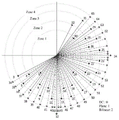
Intra prediction mode: to support finer angle prediction, the angle prediction mode can be extended to 62, and in addition to 3 special intra modes, 65 modes are provided. Referring to fig. 1D, which is a schematic diagram of the intra prediction mode, the mode numbers 1-33 of the original angle prediction modes are unchanged, and the mode number of the newly added angle prediction mode is increased from 34 to 65.
The video coding framework comprises the following steps: referring to fig. 1E, the encoding end processing flow in the embodiment of the present application may be implemented by using a video encoding frame, a schematic diagram of a video decoding frame is similar to that in fig. 1E, and details are not repeated here, and the decoding end processing flow in the embodiment of the present application may be implemented by using a video decoding frame. In the video encoding and decoding frameworks, there may be included, but not limited to: intra prediction, motion estimation/motion compensation, reference picture buffer, in-loop filtering, reconstruction, transformation, quantization, inverse transformation, inverse quantization, entropy encoder, etc. At the encoding end, the processing flow of the encoding end can be realized through the cooperation of the modules, and at the decoding end, the processing flow of the decoding end can be realized through the cooperation of the modules.
For example, in a video encoding process, transform refers to converting an image described in the form of pixels in a spatial domain into an image in a transform domain, and representing the image in the form of transform coefficients. Most images contain more flat areas and slowly-changed areas, so that the image energy can be distributed in a spatial domain in a dispersed manner and converted into relatively concentrated distribution in a transform domain in a proper transformation process, the frequency domain correlation among signals can be removed, and the code stream can be effectively compressed in cooperation with a quantization process.
For example, entropy coding refers to a method of lossless coding according to the principle of information entropy, and is located at the last processing module of video compression, and is used to convert a series of element symbols used for representing a video sequence into a binary code stream used for transmission or storage, where the input symbols may include quantized transform coefficients, motion vector information, prediction mode information, transform quantization related syntax, and the like, and the output data of the entropy coding module is the final code stream after the original video compression. Entropy coding can effectively remove the statistical redundancy of the video element symbols, and is one of the important tools for ensuring the compression efficiency of video coding.
And (3) secondary transformation: in the related art, different quadratic transformation matrices are used for 4 × 4 blocks and non-4 × 4 blocks. From the encoding end, transform coefficients are obtained after (DCT 2 ) transform, then 4 x 4 transform coefficients of the upper left corner are multiplied by a quadratic transform matrix to obtain new transform coefficients, and then quantization and entropy coding are carried out. From the decoding end, after inverse quantization is carried out on the transformation coefficient obtained by entropy decoding of the code stream, secondary inverse transformation is carried out on the 4-by-4 area at the upper left corner to obtain a new transformation coefficient, and then (DCT 2 ) is used for carrying out inverse transformation on the whole transformation block to obtain a residual coefficient.
Alternative Secondary Transform (AST): for the intra-frame prediction block, the transform coefficient obtained after the initial transform may be selected to be subjected to secondary transform or not, and the secondary transform aims at performing secondary transform on the low-frequency region, so that the energy is further concentrated. However, if the energy of the current block is concentrated enough, then the quadratic transform is not needed, so based on the actual coding block, whether to perform quadratic transform can be determined through RDO, and whether to perform quadratic transform on the current block can be expressed based on an explicit or implicit manner. If explicit AST is used, secondary conversion indication information is explicitly coded through a code stream, and if implicit AST is used, the conversion coefficient is adjusted to meet the preset parity characteristic.
In the related art, the default luminance intra prediction residual block needs to be transformed secondarily, but after the initial transformation is performed, if the energy of the transform coefficient after the initial transformation is sufficiently concentrated, and then the transform coefficient after the initial transformation is transformed secondarily, an overfitting phenomenon may occur, which may result in a problem of poor coding performance, i.e., the coding effect of the secondary transformation is not ideal.
In view of the above discovery, in the embodiment of the present application, the encoding end may determine whether to allow secondary transform to be performed on the current block according to a first preset condition and a second preset condition, and allow secondary transform to be performed on the current block if the current block meets the first preset condition and also meets the second preset condition, based on which, whether to perform secondary transform to the current block may be determined according to a rate distortion cost value corresponding to the current block. If the current block does not meet the first preset condition, the secondary transformation of the current block is forbidden, so that blocks which do not need to be subjected to secondary transformation are eliminated, the redundancy removing effect is achieved, and the coding performance is improved. And if the current block meets the first preset condition and the current block does not meet the second preset condition, directly determining to carry out secondary transformation on the current block.
In a possible embodiment, for the encoding side, whether to perform secondary transform on the current block may be determined by RDO, and indication information (e.g., secTuflag) is explicitly encoded to indicate whether to perform secondary transform on the current block, for example, when a value of secTuflag is a first value, it may indicate that the current block is to be subjected to secondary transform, and when the value of secTuflag is a second value, it may indicate that the current block is not to be subjected to secondary transform. For a decoding end, after an encoded bit stream is obtained, a secTuflag of a current block can be analyzed from the encoded bit stream, if the value of the secTuflag is a first value, secondary inverse transformation is determined to be performed on the current block, and if the value of the secTuflag is a second value, secondary inverse transformation is not performed on the current block.
In another possible implementation, for the encoding side, whether to perform secondary transform on the current block may be determined through RDO, and whether to perform secondary transform on the current block is implicitly indicated by a target characteristic (such as parity, etc.) of a target transform coefficient matrix, rather than explicitly indicating whether to perform secondary transform on the current block through indication information, for example, whether to implicitly express secTuflag through parity of the number of odd transform coefficients of the target transform coefficient matrix, and determine whether to use secondary transform on the current block. For a decoding end, after the coded bit stream is obtained, a target transform coefficient matrix is analyzed from the coded bit stream, and a target value of a preset flag of a current block is determined according to target characteristics of the target transform coefficient matrix, that is, the target value of the preset flag of the current block is deduced. And if the target value of the preset zone bit is the first value, determining to perform secondary inverse transformation on the current block. And if the target value of the preset zone bit is the second value, determining that the current block is not subjected to secondary inverse transformation.
For example, based on the above two cases, for the encoding end, if it is determined that the current block needs to be transformed twice, it may be determined whether to transform the top-left region 4 × 4 twice or to transform the 8 × 8 region twice based on the size constraint condition. For the decoding end, if it is determined that the current block needs to be subjected to the secondary inverse transformation, it may be determined whether to perform the secondary inverse transformation on the region at the top left corner 4 × 4 or perform the secondary inverse transformation on the region at 8 × 8 based on the size limitation condition.
The encoding method and the decoding method according to the embodiments of the present application will be described in detail below with reference to several specific embodiments.
Example 1: referring to fig. 2A, a flowchart of an encoding method is shown, which can be applied to an encoding end, and the method includes:
Illustratively, the first preset condition includes that the prediction mode of the current block is an intra prediction mode. The second preset condition includes: the current block uses the intra prediction filtering mode or does not use the intra prediction filtering mode.
In a possible embodiment, the first preset condition may include at least one of the following conditions: the current block is a brightness block; the initial transformation coefficient matrix of the current block contains non-zero transformation coefficients.
In a possible implementation, the first preset condition may further include: the mode number of the intra-frame prediction mode adopted by the current block is positioned in the first mode number interval, and the reference sample on the left outside the current block is available; alternatively, the mode number of the intra prediction mode adopted by the current block is located in the second mode number interval, and the reference samples outside and above the current block are available.
Illustratively, the first pattern number interval may include, but is not limited to: mode No. 0 to mode No. 2, mode No. 13 to mode No. 32, and mode No. 44 to mode No. 65. The second pattern number interval may include, but is not limited to: mode number 0 to mode number 23, and mode number 34 to mode number 57. Of course, the above is only an example of the first pattern number section and the second pattern number section, and is not limited thereto.
In a possible implementation, the first preset condition may further include: the current block is subjected to initial transformation by adopting a transformation check (DCT 2 ); alternatively, the current block is not initially transformed using a transform kernel (DST 7 ).
Illustratively, in the IST technique, as shown in table 2, if istTuflag is equal to a first value (e.g. 0), it indicates that the current block is initially transformed using a transform check (DCT 2 ), and if istTuflag is equal to a second value (e.g. 1), it indicates that the current block is initially transformed using a transform check (DST 7 ). Based on this, the first preset condition may further include: istTuflag =0, that is, by istTuflag =0, it means that the previous block is initially transformed using the transform kernel (DCT 2 ).
In a possible implementation, the second preset condition may further include one of the following conditions:
the width and the height of the current block meet a first size condition; alternatively, the first and second electrodes may be,
the current block supports a DT partition mode; alternatively, the first and second liquid crystal display panels may be,
the current block does not support a DT partition mode; alternatively, the first and second electrodes may be,
the width and the height of the current block meet a first size condition, and the current block supports a DT partition mode; alternatively, the first and second electrodes may be,
the width and height of the current block satisfy a first size condition, and the current block does not support a DT splitting mode.
For example, if the width of the current block is less than or equal to the first value and the height of the current block is less than or equal to the second value, the width and the height of the current block satisfy the first size condition. For example, the first value may be 32 and the second value may be 32, or the first value may be 64 and the second value may be 64. Of course, the above is merely an example, and no limitation is made thereto.
Exemplarily, the encoding end determines whether to perform secondary transformation on the current block according to the rate distortion cost value corresponding to the current block, and performs secondary transformation on a transformation coefficient of a designated area located at the upper left corner in the initial transformation coefficient matrix if the current block is subjected to secondary transformation, so as to obtain a target transformation coefficient matrix; and if the current block is not subjected to secondary transformation, determining the initial transformation coefficient matrix as a target transformation coefficient matrix. And coding according to the target transformation coefficient matrix to obtain the coded bit stream of the current block.
In a possible implementation manner, the encoding side may explicitly encode indication information by which whether to perform secondary transform on the current block is indicated. Based on this, the encoding end may directly encode the target transform coefficient matrix in the encoded bitstream, and on this basis, if the current block is subjected to the secondary transform, first indication information may be added in the encoded bitstream, where the first indication information is used to indicate that the current block is subjected to the secondary transform. If the current block is not secondarily transformed, second indication information for indicating that the current block is not secondarily transformed may be added to the encoded bitstream.
In another possible embodiment, whether to secondarily transform the current block may be implicitly represented by a target characteristic (e.g., parity) of the target transform coefficient matrix, rather than explicitly represented by indication information. Based on this, the encoding according to the target transform coefficient matrix to obtain the encoded bit stream of the current block includes: determining target characteristics of a target transformation coefficient matrix according to transformation coefficients in the target transformation coefficient matrix; determining whether to adjust a target transformation coefficient matrix according to the target characteristic and a target value of a preset zone bit of the current block; and when the target value of the preset flag bit is a second value, the second value is used for indicating that the second transformation is not carried out on the current block. If the target transformation coefficient matrix is not adjusted, encoding the target transformation coefficient matrix to obtain the encoded bit stream of the current block; and if the target transformation coefficient matrix is adjusted, adjusting the transformation coefficient in the target transformation coefficient matrix so as to enable the target characteristic of the adjusted target transformation coefficient matrix to be matched with the target value of the preset flag bit, and encoding the adjusted target transformation coefficient matrix to obtain the encoding bit stream of the current block.
According to the technical scheme, in the embodiment of the application, the encoding end can judge whether to allow secondary transformation to be performed on the current block according to the first preset condition and the second preset condition, if the current block meets the first preset condition and the current block also meets the second preset condition, the secondary transformation to the current block is allowed, and based on the fact, whether to perform secondary transformation to the current block can be determined according to the rate distortion cost value corresponding to the current block. If the current block does not meet the first preset condition, the secondary transformation of the current block is forbidden, so that blocks which do not need to be subjected to secondary transformation are eliminated, the redundancy removing effect is achieved, and the coding performance is improved.
Example 2: referring to fig. 2B, a flowchart of a decoding method is shown, which can be applied to a decoding end, and the method includes:
The third preset condition may include that the prediction mode of the current block is an intra prediction mode; the fourth preset condition may include: the current block uses an intra prediction filtering mode or does not use the intra prediction filtering mode.
In a possible implementation, the third preset condition may include at least one of the following conditions: the current block is a brightness block; the initial transform coefficient matrix of the current block contains non-zero transform coefficients.
In a possible implementation, the third preset condition may further include: the mode number of the intra-frame prediction mode adopted by the current block is positioned in the first mode number interval, and the reference sample on the left outside the current block is available; alternatively, the mode number of the intra prediction mode adopted by the current block is located in the second mode number interval, and the reference samples outside and above the current block are available.
For example, the first pattern number interval may include, but is not limited to: mode No. 0 to mode No. 2, mode No. 13 to mode No. 32, and mode No. 44 to mode No. 65. The second pattern number interval may include, but is not limited to: mode number 0 to mode number 23, and mode number 34 to mode number 57. Of course, the above is only an example of the first pattern number section and the second pattern number section, and this is not limited thereto.
In a possible implementation, the third preset condition may further include: the current block adopts a transformation check (DCT 2 ) to carry out initial inverse transformation; alternatively, the current block is not initially inverse transformed using the transform kernel (DST 7 ).
Illustratively, in the IST tuflag technique, if the IST tuflag is equal to a first value (e.g. 0), it indicates that the current block is initially inverse-transformed using the transform check (DCT 2 ), and if the IST tuflag is equal to a second value (e.g. 1), it indicates that the current block is initially inverse-transformed using the transform check (DST 7 ). Based on this, the third preset condition may further include: istTuflag =0, i.e. by istTuflag =0 it is indicated that the previous block was initially inverse transformed using the transform kernel (DCT 2 ).
In a possible implementation, the fourth preset condition may further include one of the following conditions:
the width and the height of the current block meet a first size condition; alternatively, the first and second electrodes may be,
the current block supports a DT partition mode; alternatively, the first and second electrodes may be,
the current block does not support a DT partition mode; alternatively, the first and second electrodes may be,
the width and the height of the current block meet a first size condition, and the current block supports a DT partition mode; alternatively, the first and second liquid crystal display panels may be,
the width and height of the current block satisfy a first size condition, and the current block does not support a DT splitting mode.
For example, if the width of the current block is less than or equal to the first value and the height of the current block is less than or equal to the second value, the width and the height of the current block satisfy the first size condition. For example, the first value may be 32 and the second value may be 32, or alternatively, the first value may be 64 and the second value may be 64. Of course, the above is merely an example and is not limited thereto.
In one possible embodiment, the encoding end may explicitly encode indication information to indicate whether to secondarily transform the current block. Based on this, the decoding end determining whether to perform inverse secondary transform on the current block according to the indication information in the encoded bit stream may include: the indication information is parsed from the coded bit stream. If the indication information is first indication information, determining to perform secondary inverse transformation on the current block; the first indication information is used for indicating that the current block is subjected to secondary transformation; or if the indication information is second indication information, determining that the current block is not subjected to secondary inverse transformation; the second indication information indicates that the current block is not secondarily transformed.
In another possible embodiment, the encoding end may implicitly indicate whether to secondarily transform the current block through a target characteristic (such as parity) of the target transform coefficient matrix, rather than explicitly indicating through indication information. Based on this, the determining, by the decoding end, whether to perform inverse secondary transform on the current block according to the target transform coefficient matrix in the encoded bitstream may include: parsing a target transform coefficient matrix from the encoded bitstream; and determining the target characteristics of the target transformation coefficient matrix according to the transformation coefficients in the target transformation coefficient matrix. Determining a target value of a preset zone bit of the current block according to the target characteristics; and when the target value of the preset zone bit is a second value, the target value of the preset zone bit is used for indicating that the current block is not subjected to secondary inverse transformation. And determining whether to perform secondary inverse transformation on the current block according to the target value of the preset zone bit.
For example, after determining whether to perform inverse secondary transformation on the current block according to the encoded bit stream, the decoding end may parse a target transformation coefficient matrix from the encoded bit stream; if the current block is subjected to secondary inverse transformation, performing secondary inverse transformation on a transformation coefficient of a specified area positioned at the upper left corner in the target transformation coefficient matrix to obtain an initial transformation coefficient matrix; and if the current block is not subjected to secondary inverse transformation, determining the target transformation coefficient matrix as the initial transformation coefficient matrix. And performing initial inverse transformation on the initial transformation coefficient matrix to obtain a residual coefficient matrix corresponding to the current block, and determining a reconstruction value of the current block according to the residual coefficient matrix.
As can be seen from the foregoing technical solutions, in the embodiment of the present application, the decoding end may determine whether to allow performing secondary inverse transformation on the current block according to a third preset condition and a fourth preset condition, for example, if the current block meets the third preset condition and also meets the fourth preset condition, the decoding end allows performing secondary inverse transformation on the current block, and determines whether to perform secondary inverse transformation on the current block according to the coded bit stream of the current block. If the current block does not meet the third preset condition, the secondary inverse transformation of the current block is forbidden, namely, the decoding end directly determines that the current block does not carry out the secondary inverse transformation, so that blocks which do not need to carry out the secondary transformation are eliminated, the redundancy removing effect is realized, and the coding performance is improved.
Example 3: referring to fig. 3A, a flow chart of an encoding method is schematically shown, which can be applied to an encoding end, and the method includes:
For example, a reference block corresponding to the current block may be determined, for each pixel point of the current block, a reference point corresponding to the pixel point is determined from the reference block, a difference value between a pixel value of the pixel point and a pixel value of the reference point is a residual coefficient corresponding to the pixel point, and residual coefficients corresponding to all pixel points of the current block form a residual coefficient matrix corresponding to the current block.
Illustratively, the residual coefficient matrix may be initially transformed by using a transformation check (DCT 2 ) to obtain an initial transformation coefficient matrix, or the residual coefficient matrix may be initially transformed by using a transformation check (DST 7 ) to obtain an initial transformation coefficient matrix. Illustratively, when the residual coefficient matrix is initially transformed by using the transform kernel (DCT 2 ), the initial transformation process may be shown in equation (3), where matrix a is DCT2 (see table 1) and matrix B is also DCT2. When the residual coefficient matrix is initially transformed by using the transformation checkups (DST 7 ), the initial transformation process can be shown in formula (3), where a is DST7 (see table 1), and B is also DST7.
As to whether the residual coefficient matrix is initially transformed by the transform kernel (DCT 2 ) or by the transform kernel (DST 7 ), the following may be used: sr _ x represents the abscissa of the rightmost non-zero transform coefficient in the residual coefficient matrix, sr _ y represents the ordinate of the bottommost non-zero transform coefficient in the residual coefficient matrix, and sr _ x and sr _ y can determine the corresponding regions of all non-zero transform coefficients in the residual coefficient matrix, and the regions beyond the regions are all 0. If sr _ x is greater than or equal to 16 or sr _ y is greater than or equal to 16, the encoding end adopts a transformation check (DCT 2 ) to carry out initial transformation on the residual coefficient matrix. Otherwise, the encoding end selects whether to adopt the transformation check (DCT 2 ) or the transformation check (DST 7 ) through RDO. For example, if the rate-distortion cost value of the transform check (DCT 2 ) is less than the rate-distortion cost value of the transform check (DST 7 ), performing initial transform on the residual coefficient matrix by using the transform check (DCT 2 ); if the rate-distortion cost value of the transformation check (DCT 2 ) is greater than the rate-distortion cost value of the transformation check (DST 7 ), the residual coefficient matrix is initially transformed using the transformation check (DST 7 ).
Of course, the above is only an example of obtaining the initial transform coefficient matrix by performing the initial transform on the residual coefficient matrix, and this is not limited to this, as long as the initial transform can be performed on the residual coefficient matrix to obtain the initial transform coefficient matrix.
313, if the current block supports the secondary transformation, the current block supports the AST technology, and the current block meets a first preset condition, determining whether the current block meets a second preset condition; and if the current block meets the second preset condition, determining whether to carry out secondary transformation on the current block according to the rate distortion cost value corresponding to the current block.
For example, if the value of the quadratic transform enabled flag (e.g., secondaryTransformEnableFlag) is a preset value (e.g., 1), it is determined that the current block supports quadratic transform. When the value of the quadratic transformation enabling flag is a preset value, it indicates that the quadratic transformation is allowed to be enabled at a sequence level or a frame level, that is, the current block is allowed to be enabled, and therefore, the encoding end determines that the current block supports the quadratic transformation.
For example, if the value of the selectable secondary transform enable flag (e.g., astEnableFlag) is a preset value (e.g., 1), it is determined that the AST technology is supported by the current block. When the selectable secondary transform enable flag is a preset value, it indicates that the AST technology is enabled at a sequence level or a frame level, that is, the AST technology is enabled for the current block, and therefore, the encoding side determines that the AST technology is supported by the current block.
For example, if the current block does not support the quadratic transform, the encoding end determines not to perform the quadratic transform on the current block. If the current block supports the secondary transformation but does not support the AST technology, the encoding end determines not to carry out the secondary transformation on the current block.
If the current block supports the secondary transformation and supports the AST technology, the encoding end judges whether the current block meets a first preset condition. And if the current block does not meet the first preset condition, the encoding end determines not to carry out secondary transformation on the current block.
If the current block supports the secondary transformation, the current block supports the AST technology, and the current block meets the first preset condition, the encoding end determines whether the current block meets the second preset condition. If the current block does not meet the second preset condition, the encoding end directly determines to carry out secondary transformation on the current block, and does not adopt the RDO and other modes to decide whether to carry out secondary transformation.
If the current block supports the secondary transformation, the current block supports the AST technology, and the current block meets the first preset condition, the encoding end determines whether the current block meets the second preset condition. And if the current block meets the second preset condition, the coding end determines whether to carry out secondary transformation on the current block according to the rate distortion cost value corresponding to the current block. For example, a first rate-distortion cost value when only the initial transform is performed on the current block is determined, and a second rate-distortion cost value when the initial transform is performed on the current block and then the second transform is performed on the current block is determined. And if the second rate distortion cost value is smaller than the first rate distortion cost value, determining to carry out secondary transformation on the current block. And if the second rate distortion cost value is larger than the first rate distortion cost value, determining not to carry out secondary transformation on the current block.
When the first rate distortion cost value of only performing initial transformation on the current block is determined, the coding end performs initial transformation on the residual coefficient matrix to obtain an initial transformation coefficient matrix, and determines the first rate distortion cost value corresponding to the current block based on the initial transformation coefficient matrix.
When determining a second rate distortion cost value when performing initial transformation and then performing secondary transformation on the current block, the encoding end performs initial transformation on the residual coefficient matrix to obtain an initial transformation coefficient matrix, performs secondary transformation on the initial transformation coefficient matrix to obtain a target transformation coefficient matrix, determines the second rate distortion cost value corresponding to the current block based on the target transformation coefficient matrix, and does not limit the determination mode, and can determine the second rate distortion cost value corresponding to the current block by using RDO.
In the above embodiment, it needs to be determined whether the current block satisfies a first preset condition, and for the first preset condition, in a possible implementation manner, the first preset condition may include but is not limited to at least one of the following conditions:
condition 1: the prediction mode of the current block is an intra prediction mode.
Condition 2: the current block is a luminance block.
Condition 3: the initial transform coefficient matrix of the current block contains non-zero transform coefficients.
The fact that the initial transform coefficient matrix of the current block contains non-zero transform coefficients means that: after the initial transform is performed on the residual coefficient matrix to obtain an initial transform coefficient matrix, if all transform coefficients in the initial transform coefficient matrix are zero, it indicates that the initial transform coefficient matrix does not contain a non-zero transform coefficient, in this case, the cbf flag of the current block is a first value (for example, a value 0), and the transform coefficient of the current block does not need to be encoded. If all the transform coefficients in the initial transform coefficient matrix are not zero (i.e. any one or more transform coefficients are not zero), it means that the initial transform coefficient matrix contains non-zero transform coefficients, in this case, the cbf flag of the current block is set to a second value (e.g. value 1), and the transform coefficient of the current block needs to be encoded.
Condition 4: the mode number of the intra-frame prediction mode adopted by the current block is positioned in the first mode number interval, and the reference sample on the left outside the current block is available; alternatively, the mode number of the intra prediction mode adopted by the current block is located in the second mode number interval, and the reference samples outside and above the current block are available. Illustratively, the first pattern number section may include pattern number 0 to pattern number 2, pattern number 13 to pattern number 32, and pattern number 44 to pattern number 65. The second mode number section may include mode number 0 to mode number 23, and mode number 34 to mode number 57. Of course, the above is only an example of the first pattern number section and the second pattern number section, and this is not limited thereto.
Condition 5: the current block adopts a transformation check (DCT 2 ) to carry out initial transformation; alternatively, the current block is not initially transformed using the transform kernel (DST 7 ). Alternatively, istTuflag is equal to the first value (e.g., 0).
Referring to step 312, the encoding side performs initial transformation on the residual coefficient matrix by using a transformation check (DCT 2 ), or performs initial transformation on the residual coefficient matrix by using a transformation check (DST 7 ).
The condition 5 is satisfied if the residual coefficient matrix is initially transformed by the transform kernel (DCT 2 ), and the condition 5 is not satisfied if the residual coefficient matrix is initially transformed by the transform kernel (DST 7 ).
For example, the first preset condition may include only condition 1 and condition 2. Alternatively, the first preset condition may include only condition 1, condition 2 and condition 5. Alternatively, the first preset condition may include condition 1, condition 2 and condition 5, and on this basis, the first preset condition may further include condition 4 and/or condition 5, which is only an example and is not limited thereto.
When the first preset condition includes condition 4, the first preset condition only includes one of conditions 4, for example, the first preset condition may include that the mode number of the intra prediction mode adopted by the current block is located in the first mode number interval, and the reference sample outside and on the left of the current block is available. Alternatively, the first preset condition may include that the mode number of the intra prediction mode adopted by the current block is located in the second mode number interval, and the reference samples outside and above the current block are available.
When the first preset condition includes the condition 5, the first preset condition only includes one of the conditions 5, for example, the first preset condition may include that the current block is initially transformed by using a transform kernel (DCT 2 ). Alternatively, the first preset condition may include that the current block is not initially transformed using the transform kernel (DST 7 ).
The following describes different situations of the first preset condition with reference to several specific application scenarios.
Application scenario 1: the first preset condition may include: the prediction mode of the current block is an intra prediction mode.
Application scenario 2: the first preset condition may include: the prediction mode of the current block is an intra prediction mode. The current block is a luminance block.
Application scenario 3: the first preset condition may include: the prediction mode of the current block is an intra prediction mode. The current block is a luminance block. The current block is initially transformed using a transform kernel (DCT 2 ).
Application scenario 4: the first preset condition may include: the prediction mode of the current block is an intra prediction mode. The current block is a luminance block. The current block is not initially transformed using a transformation checkup (DST 7 ).
Application scenario 5: on the basis of any one of the application scenarios 1 to 4, the first preset condition may further include: the mode number of the intra prediction mode adopted by the current block is located in the first mode number interval, and the reference samples outside the current block to the left are available.
Application scenario 6: on the basis of any one of the application scenarios 1 to 4, the first preset condition may further include: the mode number of the intra prediction mode adopted by the current block is located in the second mode number interval, and the reference samples on the upper side outside the current block are available.
Application scenario 7: on the basis of any one of the application scenarios 1-6, the first preset condition may further include: the initial transformation coefficient matrix of the current block contains non-zero transformation coefficients.
Of course, the above application scenarios 1-7 are also only a few examples of the first preset condition, and the first preset condition is not limited. Taking the application scenario 3 as an example, the current block satisfying the first preset condition means: if the prediction mode of the current block is an intra-frame prediction mode, the current block is a brightness block, and the current block is subjected to initial transformation by adopting a transformation check (DCT 2 ), the current block meets a first preset condition. If the prediction mode of the current block is not the intra-frame prediction mode, the current block does not meet the first preset condition, or if the current block is not a brightness block, the current block does not meet the first preset condition, or if the current block does not adopt the transformation check (DCT 2 ) to carry out the initial transformation, the current block does not meet the first preset condition.
In the above embodiment, it is required to determine whether the current block satisfies a second preset condition, and for the second preset condition, in a possible implementation, the second preset condition may include, but is not limited to, at least one of the following conditions:
condition a: the current block uses an intra prediction filtering mode, or the current block does not use the intra prediction filtering mode.
Condition b: the current block supports a DT partition mode; alternatively, the current block does not support the DT division mode.
Condition c: the width and height of the current block satisfy a first size condition. For example, if the width of the current block is less than or equal to the first value and the height of the current block is less than or equal to the second value, the width and the height of the current block satisfy the first size condition.
For example, the first value may be 32 or 64, and the second value may be 32 or 64, however, 32 and 64 are only examples, and this is not limited thereto, for example, the first value may also be 128, the second value may also be 128, and so on. For example, the first value may be 32 and the second value may be 32, or the first value may be 64 and the second value may be 64.
Illustratively, the second preset condition may include only the condition a. Alternatively, the second preset condition may include only the condition a and the condition b. Alternatively, the second preset condition may include only the condition a and the condition c. Alternatively, the second preset condition may include only the condition b. Alternatively, the second preset condition may include only the condition b and the condition c. Alternatively, the second preset condition may include condition a, condition b and condition c. Of course, the above is merely an example, and no limitation is made thereto.
When the second predetermined condition includes the condition a, only one case of the condition a may be included, for example, the second predetermined condition includes that the current block uses the intra prediction filtering mode. Alternatively, the second preset condition includes that the current block does not use the intra prediction filtering mode.
When the second predetermined condition includes the condition b, only one case of the condition b may be included, for example, the second predetermined condition includes that the current block supports the DT partition mode. Or, the second preset condition includes that the current block does not support the DT division mode.
The following describes different situations of the second preset condition with reference to several specific application scenarios.
Application scenario 8: the second preset condition may include: the current block uses an intra prediction filtering mode.
Application scenario 9: the second preset condition may include: the current block does not use the intra prediction filtering mode.
Application scenario 10: the second preset condition may include: the current block supports the DT division mode.
Application scenario 11: the second preset condition may include: the current block does not support the DT division mode.
Application scenario 12: the second preset condition may include: the current block uses an intra prediction filtering mode. The current block supports the DT division mode.
Application scenario 13: the second preset condition may include: the current block uses an intra prediction filtering mode. The current block does not support the DT division mode.
Application scenario 14: the second preset condition may include: the current block does not use the intra prediction filtering mode. The current block supports the DT division mode.
Application scenario 15: the second preset condition may include: the current block does not use the intra prediction filtering mode. The current block does not support the DT division mode.
Application scenario 16: on the basis of any one of the application scenarios 8-15, the second preset condition may further include: the width and height of the current block satisfy a first size condition.
Of course, the above application scenarios 8-16 are also only a few examples of the second preset condition, and the second preset condition is not limited. Taking the application scenario 12 as an example, the current block satisfying the second preset condition means: if the current block uses the intra-frame prediction filtering mode and the current block supports the DT partition mode, it indicates that the current block satisfies the second preset condition. If the current block does not use the intra-frame prediction filtering mode, the current block does not meet the second preset condition, or if the current block does not support the DT partition mode, the current block does not meet the second preset condition.
In one possible embodiment, the secondary transformation is performed on the transform coefficients of the designated area located at the upper left corner in the initial transform coefficient matrix, which may include but is not limited to: and if the width and the height of the current block meet the second size condition, performing secondary transformation on the transformation coefficient of a first specified area positioned at the upper left corner in the initial transformation coefficient matrix based on the secondary transformation matrix of the first specified size. And if the width and the height of the current block do not meet the second size condition, performing secondary transformation on the transformation coefficient of a second designated area positioned at the upper left corner in the initial transformation coefficient matrix based on a secondary transformation matrix of a second designated size.
Illustratively, the first designated area has a size of a first designated size and the second designated area has a size of a second designated size, the first designated size being greater than the second designated size. For example, the first specified size is 8 by 8; the second finger is sized 4 x 4. Of course, the above is merely an example of the first and second designated sizes, and the first and second designated sizes are not limited thereto.
The width and height of the current block satisfy the second size condition, which may include but are not limited to: the width of the current block is larger than or equal to a third numerical value, and the height of the current block is larger than or equal to a fourth numerical value; or the width of the current block is greater than or equal to the fifth numerical value, and the height of the current block is greater than the sixth numerical value; or the width of the current block is larger than the seventh value, and the height of the current block is larger than or equal to the eighth value.
For example, the third, fourth, fifth, sixth, seventh, and eighth values may be configured empirically, and are not limited to these values. For example, the third numerical value may be 8 or 16, the fourth numerical value may be 8 or 16, the fifth numerical value may be 8 or 16, the sixth numerical value may be 8 or 16, the seventh numerical value may be 8 or 16, and the eighth numerical value may be 8 or 16.
In summary, if the width and the height of the current block satisfy the second size condition (for example, the width of the current block is greater than or equal to 8, and the height of the current block is greater than or equal to 8), the transform coefficients of the first designated area located at the top left corner in the initial transform coefficient matrix (i.e., the area with the size of 8 × 8) are secondarily transformed based on the secondary transform matrix with the size of 8 × 8. And if the width and the height of the current block do not meet the second size condition, performing quadratic transformation on the transformation coefficient of a second specified area (namely, an area with the size of 4 x 4) positioned at the upper left corner in the initial transformation coefficient matrix based on the quadratic transformation matrix with the size of 4 x 4.
And 315, coding according to the target transformation coefficient matrix to obtain the coded bit stream of the current block.
In step 316, if the current block is transformed secondarily, first indication information is added to the coded bit stream of the current block, and the first indication information is used for indicating that the current block is transformed secondarily. And if the current block is not subjected to secondary transformation, adding second indication information in the coded bit stream of the current block, wherein the second indication information is used for indicating that the current block is not subjected to secondary transformation.
For example, the encoding side may explicitly encode indication information by which whether to perform secondary transform on the current block is indicated. Based on this, after obtaining the target transform coefficient matrix, the encoding end may directly encode the target transform coefficient matrix in the encoded bit stream of the current block, and add the first indication information or the second indication information in the encoded bit stream of the current block.
Illustratively, the target transform coefficient matrix is changed into an encoded bit stream through an entropy encoding process and transmitted to a decoding end, and in the process of encoding according to the target transform coefficient matrix, if the current block uses a (DST 7 ) transform kernel to perform an initial transform, the target transform coefficient matrix after transform quantization needs to satisfy: sr _ x and sr _ y are smaller than 16, and the number of all non-zero transform coefficients in the target transform coefficient matrix is odd, which is used to indicate that the current block is initially transformed using a (DST 7 ) transform kernel. Or, if the current block is initially transformed using a (DCT 2 ) transform kernel, the transform-quantized target transform coefficient matrix needs to satisfy: and sr _ x or sr _ y is more than or equal to 16, or the number of all non-zero transform coefficients in the target transform coefficient matrix is an even number, and the number is used for indicating that the current block is subjected to initial transform by using a (DCT 2 ) transform kernel.
Illustratively, if the current block supports the secondary transform, the current block supports the AST technology, the current block satisfies a first preset condition, the current block satisfies a second preset condition, and after determining whether to perform the secondary transform on the current block according to a rate-distortion cost value corresponding to the current block, the indication information is added to the encoded bitstream of the current block, for example, if the current block is subjected to the secondary transform, the first indication information is added to the encoded bitstream, and if the current block is not subjected to the secondary transform, the second indication information is added to the encoded bitstream.
If the current block does not support the secondary transformation, determining that the secondary transformation is not performed on the current block, but not adding indication information in the coded bit stream of the current block. Or, if the current block supports the secondary transform and does not support the AST technology, determining that the secondary transform is not performed on the current block, but not adding the indication information in the encoded bitstream of the current block. Or, if the current block supports the secondary transform, the current block supports the AST technology, and the current block does not meet the first preset condition, determining not to perform the secondary transform on the current block, but not adding the indication information in the coding bit stream of the current block. Or, if the current block supports secondary transformation, the current block supports the AST technology, the current block satisfies a first preset condition, and the current block does not satisfy a second preset condition, determining to perform secondary transformation on the current block, but without adding indication information in the encoded bitstream of the current block.
In the above case, the fact that the indication information does not need to be added to the encoded bitstream of the current block means that the indication information for indicating that the current block is not secondarily transformed or that the current block is secondarily transformed does not need to be added.
As can be seen from the above technical solutions, in the embodiment of the present application, the encoding end may determine whether to allow secondary transformation to be performed on the current block according to the first preset condition and the second preset condition, and allow secondary transformation to be performed on the current block if the current block meets the first preset condition and also meets the second preset condition, based on which, whether to perform secondary transformation to the current block may be determined according to the rate distortion cost value corresponding to the current block. If the current block does not meet the first preset condition, the secondary transformation of the current block is forbidden, so that blocks which do not need to be subjected to the secondary transformation are removed, the redundancy removing effect is achieved, and the coding performance is improved.
Example 4: referring to fig. 3B, a flowchart of a decoding method is shown, which can be applied to a decoding end, and the method includes:
For example, if the value of the quadratic transform enabled flag (e.g., secondaryTransformEnableFlag) is a preset value (e.g., 1), it is determined that the current block supports quadratic transform. When the value of the secondary transform enabling flag is a preset value, it indicates that the secondary transform is allowed to be enabled at a sequence level or a frame level, that is, the secondary transform is allowed to be enabled for the current block, and therefore, the decoding end determines that the current block supports the secondary transform.
For example, if the value of the selectable secondary transform enable flag (e.g., astEnableFlag) is a preset value (e.g., 1), it is determined that the AST technology is supported by the current block. When the selectable secondary transform enable flag is a preset value, it indicates that the AST technology is enabled at a sequence level or a frame level, that is, the AST technology is enabled for the current block, and thus, the decoding side determines that the AST technology is supported by the current block.
For example, if the current block does not support the secondary transform, the decoding end determines not to perform the secondary inverse transform on the current block. If the current block supports the secondary transformation but does not support the AST technology, the decoding end determines not to perform secondary inverse transformation on the current block.
If the current block supports the secondary transformation and the current block supports the AST technology, the decoding end judges whether the current block meets a third preset condition. And if the current block does not meet the third preset condition, the decoding end determines not to perform secondary inverse transformation on the current block.
If the current block supports the secondary transformation, the current block supports the AST technology, and the current block meets a third preset condition, the decoding end determines whether the current block meets a fourth preset condition. And if the current block does not meet the fourth preset condition, determining to carry out secondary inverse transformation on the current block without determining whether to carry out secondary inverse transformation on the current block according to the indication information in the coded bit stream.
If the current block supports the secondary transformation, the current block supports the AST technology, and the current block meets a third preset condition, the decoding end determines whether the current block meets a fourth preset condition. If the current block meets the fourth preset condition, the decoding end analyzes the indication information from the coded bit stream and determines whether to carry out secondary inverse transformation on the current block according to the indication information. For example, the encoding side may explicitly encode indication information to indicate whether to secondarily transform the current block. Based on this, the decoding end parses the indication information from the coded bitstream. If the indication information is first indication information, determining to perform secondary inverse transformation on the current block; the first indication information is used for indicating that the current block is subjected to secondary transformation; or if the indication information is second indication information, determining that the current block is not subjected to secondary inverse transformation; the second indication information indicates that the current block is not secondarily transformed.
In the above embodiment, the decoding side needs to determine whether the current block satisfies a third preset condition, and for the third preset condition, in a possible implementation manner, the third preset condition may include but is not limited to at least one of the following conditions:
condition 1: the prediction mode of the current block is an intra prediction mode.
Condition 2: the current block is a luminance block.
Condition 3: the initial transformation coefficient matrix of the current block contains non-zero transformation coefficients.
Illustratively, if the initial transform coefficient matrix does not contain non-zero transform coefficients, the cbf flag of the current block is a first value (e.g., value 0), and if the initial transform coefficient matrix contains non-zero transform coefficients (i.e., any one or more transform coefficients are not zero), the cbf flag of the current block is a second value (e.g., value 1). Based on this, the decoding end can parse the cbf flag bit from the encoded bitstream, and if the cbf flag bit is the first value, it is determined that the initial transform coefficient matrix does not contain the non-zero transform coefficient, that is, all the transform coefficients in the initial transform coefficient matrix are zero. And if the cbf flag bit is the second numerical value, determining that the initial transformation coefficient matrix contains non-zero transformation coefficients, namely all the transformation coefficients in the initial transformation coefficient matrix are not zero.
Condition 4: the mode number of the intra-frame prediction mode adopted by the current block is positioned in the first mode number interval, and the reference sample on the left outside the current block is available; alternatively, the mode number of the intra prediction mode adopted by the current block is located in the second mode number interval, and the reference samples outside and above the current block are available. Illustratively, the first pattern number section may include pattern number 0 to pattern number 2, pattern number 13 to pattern number 32, and pattern number 44 to pattern number 65. The second mode number section may include mode number 0 to mode number 23, and mode number 34 to mode number 57. Of course, the above is only an example of the first pattern number section and the second pattern number section, and is not limited thereto.
Condition 5: the current block is subjected to initial inverse transformation by adopting a transformation check (DCT 2 ); or, the current block is not initially inverse transformed using the transform verify (DST 7 ). Alternatively, istTuflag is equal to the first value (e.g., 0).
For example, the condition 5 is satisfied when the initial inverse transform is performed by using the transform matching (DCT 2 ), and the condition 5 is not satisfied when the initial inverse transform is performed by using the transform matching (DST 7 ).
Illustratively, the decoding side determines whether the current block is initially inverse-transformed by using the transform check (DCT 2 ) or the transform check (DST 7 ), and the following method can be adopted: the decoding end analyzes the coded bit stream to obtain sr _ x and sr _ y, and when sr _ x is larger than or equal to 16 or sr _ y is larger than or equal to 16, the decoding end can directly judge that the current block adopts the transformation check (DCT 2 ) to carry out initial inverse transformation. When sr _ x is less than 16 and sr _ y is less than 16, the decoding end may determine the parity of the number of all non-zero transform coefficients in the target transform coefficient matrix. If the parity is odd, the decoding end may determine that the current block is initially inverse-transformed by using the transform check (DST 7 ), and if the parity is even, the decoding end may determine that the current block is initially inverse-transformed by using the transform check (DCT 2 ).
Of course, the above-mentioned method is only an example, and is not limited thereto, as long as it can be determined whether the current block is initially inverse-transformed by using the transform check (DCT 2 ) or initially inverse-transformed by using the transform check (DST 7 ).
Illustratively, the third preset condition may include only condition 1 and condition 2. Alternatively, the third preset condition may include only condition 1, condition 2 and condition 5. Alternatively, the third preset condition may include condition 1, condition 2 and condition 5, and on this basis, the third preset condition may further include condition 4 and/or condition 5, which is only an example and is not limited thereto.
For example, the third preset condition is similar to the first preset condition, and details are not repeated here.
In the above embodiment, it needs to be determined whether the current block satisfies a fourth preset condition, and for the fourth preset condition, in a possible implementation manner, the fourth preset condition may include but is not limited to at least one of the following conditions:
condition a: the current block uses the intra prediction filtering mode, or the current block does not use the intra prediction filtering mode.
Condition b: the current block supports a DT partitioning mode; alternatively, the current block does not support the DT division mode.
Condition c: the width and height of the current block satisfy a first size condition. For example, if the width of the current block is less than or equal to the first value and the height of the current block is less than or equal to the second value, the width and the height of the current block satisfy the first size condition.
For example, the first value may be 32 or 64, and the second value may be 32 or 64, although 32 and 64 are only examples and not limitations, e.g., the first value may also be 128, the second value may also be 128, etc. For example, the first value may be 32 and the second value may be 32, or the first value may be 64 and the second value may be 64.
Illustratively, the fourth preset condition may include only the condition a. Alternatively, the fourth preset condition may include only the condition a and the condition b. Alternatively, the fourth preset condition may include only the condition a and the condition c. Alternatively, the fourth preset condition may include only the condition b. Alternatively, the fourth preset condition may include only the condition b and the condition c. Alternatively, the fourth preset condition may include condition a, condition b and condition c. Of course, the above is merely an example, and no limitation is made thereto.
For example, the fourth preset condition is similar to the second preset condition, and details are not repeated here.
In step 323, the target transform coefficient matrix of the current block is parsed from the encoded bitstream.
For example, performing the inverse quadratic transform on the transform coefficient of the specified region located at the top left corner in the target transform coefficient matrix may include, but is not limited to: if the width and height of the current block satisfy the second size condition, the transform coefficients of the first designated area located at the top left corner in the target transform coefficient matrix may be inversely transformed twice based on the inverse quadratic transform matrix of the first designated size (the inverse quadratic transform matrix may be the same as the inverse quadratic transform matrix used when the encoding end performs the inverse transform). If the width and height of the current block do not satisfy the second size condition, transform coefficients of a second designated area located at the upper left corner in the target transform coefficient matrix may be secondarily inverse-transformed based on an inverse-transform-quadratic matrix of a second designated size.
Illustratively, the first designated area has a size of a first designated size and the second designated area has a size of a second designated size, the first designated size being greater than the second designated size. For example, the first specified size is 8 by 8; the second finger is sized 4 x 4. Of course, the above is merely an example of the first designated size and the second designated size, and the first designated size and the second designated size are not limited thereto.
The width and height of the current block satisfy the second size condition, which may include but is not limited to: the width of the current block is greater than or equal to a third numerical value, and the height of the current block is greater than or equal to a fourth numerical value; or the width of the current block is greater than or equal to the fifth numerical value, and the height of the current block is greater than the sixth numerical value; or, the width of the current block is greater than the seventh value, and the height of the current block is greater than or equal to the eighth value.
For example, the third numerical value, the fourth numerical value, the fifth numerical value, the sixth numerical value, the seventh numerical value, and the eighth numerical value may be configured empirically, and are not limited to these numerical values. For example, the third numerical value may be 8 or 16, the fourth numerical value may be 8 or 16, the fifth numerical value may be 8 or 16, the sixth numerical value may be 8 or 16, the seventh numerical value may be 8 or 16, and the eighth numerical value may be 8 or 16.
In summary, if the width and the height of the current block satisfy the second size condition (for example, the width of the current block is greater than or equal to 8, and the height of the current block is greater than or equal to 8), the transform coefficients of the first designated area located at the top left corner in the target transform coefficient matrix (i.e., the area with the size of 8 × 8) are inversely transformed twice based on the inverse transform matrix with the size of 8 × 8. If the width and the height of the current block do not meet the second size condition, performing secondary inverse transformation on the transformation coefficient of a second designated area (namely, an area with the size of 4 x 4) positioned at the upper left corner in the target transformation coefficient matrix based on the secondary inverse transformation matrix with the size of 4 x 4.
For example, referring to condition 8 in the above embodiment, the decoding end may determine whether the current block uses the transform check (DCT 2 ) to perform the initial inverse transform or uses the transform check (DST 7 ) to perform the initial inverse transform, and details of this determination method are not repeated. If the transform check (DCT 2 ) is used to perform the initial inverse transform, the decoding end may use the transform check (DCT 2 ) to perform the initial inverse transform on the initial transform coefficient matrix, so as to obtain a residual coefficient matrix corresponding to the current block. Or, if the initial inverse transformation is performed by using the transformation checkup (DST 7 ), the decoding end may perform the initial inverse transformation on the initial transformation coefficient matrix by using the transformation checkup (DST 7 ) to obtain the residual coefficient matrix corresponding to the current block.
In step 326, the reconstructed value of the current block is determined according to the residual coefficient matrix.
For example, a reference block corresponding to the current block may be determined, for each pixel of the current block, a reference point corresponding to the pixel is determined from the reference block, and a residual coefficient value corresponding to the pixel is determined from the residual coefficient matrix. And obtaining a reconstruction value of the pixel point according to the pixel value of the reference point and the residual coefficient value. The reconstructed values corresponding to all the pixel points of the current block can constitute the reconstructed value of the current block. Of course, the above-described manner is merely an example, and is not limited thereto.
To sum up, the decoding end may obtain the istTuflag according to the parity of the number of all non-zero transform coefficients in the target transform coefficient matrix, and sr _ x and sr _ y. If istTuflag is equal to 0, it means that the current block is initially inverse-transformed using the transform kernel (DCT 2 ), and if istTuflag is equal to 1, it means that the current block is initially inverse-transformed using the transform kernel (DST 7 ). And when the istTuflag is equal to 0 and secondary inverse transformation is required to be carried out on the current block, carrying out secondary inverse transformation on the target transformation coefficient matrix by the decoding end to obtain an initial transformation coefficient matrix, and then carrying out initial inverse transformation on the initial transformation coefficient matrix to obtain a residual error coefficient matrix. And when the istTuflag is equal to 0 and secondary inverse transformation is not required to be performed on the current block, the decoding end determines the target transformation coefficient matrix as an initial transformation coefficient matrix, and performs initial inverse transformation on the initial transformation coefficient matrix to obtain a residual coefficient matrix. And when the istTuflag is equal to 1, the decoding end determines the target transformation coefficient matrix as an initial transformation coefficient matrix, and performs initial inverse transformation on the initial transformation coefficient matrix to obtain a residual error coefficient matrix.
Then, the reconstruction value of the current block can be determined by the residual coefficient matrix, and the reconstruction process is not described again.
As can be seen from the foregoing technical solutions, in the embodiment of the present application, the decoding end may determine whether to allow performing secondary inverse transformation on the current block according to a third preset condition and a fourth preset condition, for example, if the current block meets the third preset condition and also meets the fourth preset condition, the decoding end allows performing secondary inverse transformation on the current block, and determines whether to perform secondary inverse transformation on the current block according to the coded bit stream of the current block. If the current block does not meet the third preset condition, the secondary inverse transformation of the current block is forbidden, namely, the decoding end directly determines that the current block does not carry out the secondary inverse transformation, so that blocks which do not need to carry out the secondary transformation are eliminated, the redundancy removing effect is realized, and the coding performance is improved.
Example 5: referring to fig. 4A, a flow chart of an encoding method is schematically shown, which can be applied to an encoding end, and the method includes:
In step 412, the residual coefficient matrix is subjected to initial transformation to obtain an initial transformation coefficient matrix.
For example, steps 411 to 414 can refer to steps 311 to 314, which are not described herein.
Illustratively, the target feature may be a target parity, which may include, but is not limited to: parity of the number of all odd transform coefficients in the target transform coefficient matrix; for example, if there are 30 odd transform coefficients in the target transform coefficient matrix, the parity of all the odd transform coefficients is even, i.e., the target parity is even. Or, parity of the number of all even transform coefficients in the target transform coefficient matrix; for example, if 25 even transform coefficients exist in the target transform coefficient matrix, the parity of the number of all the even transform coefficients is odd, that is, the target parity is odd. Or, parity of the sum of absolute values of all transform coefficients in the target transform coefficient matrix; for example, the absolute values of all the transform coefficients in the target transform coefficient matrix are summed, and if the sum result is odd, the target parity is odd, and if the sum result is even, the target parity is even. Of course, the above target parity is only a few examples, and is not limited thereto, for example, the target parity may also be the parity of the number of coefficients with an absolute value of 1, the parity of the last non-zero transform coefficient, and the like.
The target feature may also be target positive-negative, which may include, but is not limited to: the positivity and the negativity of the last non-zero transformation coefficient in the target transformation coefficient matrix; or, the positive and negative of the first non-zero transform coefficient in the target transform coefficient matrix; or, the value of the nth non-zero transform coefficient in the target transform coefficient matrix may be configured arbitrarily according to actual needs, which is not limited to this. Of course, the target positive and negative are just a few examples, and the target positive and negative are not limited, for example, the target positive and negative may be the positive and negative of the sum of absolute values of all transform coefficients in the target transform coefficient matrix.
Of course, target parity and target negativity are just two examples of target features, and no limitation is made on this target feature. For convenience of description, the target parity is taken as an example for explanation, and the processing manner of other target features is similar.
And 416, determining whether to adjust the target transformation coefficient matrix or not according to the target characteristics and the target value of the preset zone bit of the current block. Illustratively, when the target value of the preset flag is the first value, the target value is used to indicate that the current block is to be secondarily transformed, and when the target value of the preset flag is the second value, the target value is used to indicate that the current block is not to be secondarily transformed.
For example, after determining whether to perform secondary transform on the current block according to the rate-distortion cost value corresponding to the current block, the encoding end may set a target value of the preset flag bit to a first value to indicate that the secondary transform is performed on the current block if the secondary transform is performed on the current block. If the current block is not subjected to the secondary transformation, the target value of the preset flag bit may be set as a second value to indicate that the current block is not subjected to the secondary transformation. For example, the first value may be 1 and the second value may be 0; alternatively, the first value may be 0 and the second value may be 1; of course, the above is merely an example, and no limitation is made thereto.
In a possible embodiment, the encoding end and the decoding end may agree on the relationship between the target parity and the quadratic transformation, for example, when the target parity is odd, it means that the current block is quadratic transformed, and when the target parity is even, it means that the current block is not quadratic transformed, i.e. it agrees on the relationship between "odd" and performing quadratic transformation, and "even" and not performing quadratic transformation.
In the above case, if the target parity is an odd number and the target value of the preset flag of the current block is the first value, it is determined that the target transform coefficient matrix is not adjusted, and exemplarily, if the target parity is an odd number, it indicates that the current block is transformed secondarily, and the target value of the preset flag is the first value and also indicates that the current block is transformed secondarily, so that the target transform coefficient matrix is not adjusted. Or, if the target parity is an odd number and the target value of the preset flag of the current block is the second value, it is determined to adjust the target transform coefficient matrix, for example, if the target parity is an odd number, it indicates to perform quadratic transform on the current block, and the target value of the preset flag is the second value, it indicates not to perform quadratic transform on the current block, so that the target transform coefficient matrix is adjusted. Or, if the target parity is an even number and the target value of the preset flag of the current block is the first value, it is determined to adjust the target transform coefficient matrix, for example, if the target parity is an even number, it indicates that the current block is not subjected to secondary transform, and the target value of the preset flag is the first value, which indicates that the current block is subjected to secondary transform, so that the target transform coefficient matrix is adjusted. Or, if the target parity is an even number and the target value of the preset flag of the current block is the second value, it is determined that the target transform coefficient matrix is not adjusted, for example, if the target parity is an even number, it indicates that the current block is not subjected to secondary transform, and the target value of the preset flag is the second value, which indicates that the current block is not subjected to secondary transform, so the target transform coefficient matrix is not adjusted.
In another possible embodiment, the encoding side and the decoding side may agree on the relationship between the target parity and the quadratic transformation, for example, when the target parity is even, it means quadratic transformation is performed on the current block, and when the target parity is odd, it means that no quadratic transformation is performed on the current block, i.e. an "even" and quadratic transformation are agreed on, and an "odd" and no quadratic transformation are agreed on.
In the above case, if the target parity is an even number and the target value of the preset flag of the current block is the first value, it is determined that the target transform coefficient matrix is not adjusted, for example, if the target parity is an even number, it indicates that the current block is transformed twice, and the target value of the preset flag is the first value and also indicates that the current block is transformed twice, so that the target transform coefficient matrix is not adjusted. Or, if the target parity is an even number and the target value of the preset flag of the current block is the second value, it is determined to adjust the target transform coefficient matrix, for example, if the target parity is an even number, it indicates to perform quadratic transform on the current block, and the target value of the preset flag is the second value, it indicates not to perform quadratic transform on the current block, so the target transform coefficient matrix is adjusted. Or, if the target parity is an odd number and the target value of the preset flag of the current block is the first value, it is determined to adjust the target transform coefficient matrix, for example, if the target parity is an odd number, it indicates that the current block is not subjected to secondary transform, and the target value of the preset flag is the first value, which indicates that the current block is subjected to secondary transform, so that the target transform coefficient matrix is adjusted. Or, if the target parity is an odd number and the target value of the preset flag of the current block is the second value, it is determined that the target transform coefficient matrix is not adjusted, for example, if the target parity is an odd number, it indicates that the current block is not subjected to the secondary transform, and the target value of the preset flag is the second value, which indicates that the current block is not subjected to the secondary transform, so that the target transform coefficient matrix is not adjusted.
For example, if the target transform coefficient matrix is not adjusted, step 417 is executed.
For example, if the target transform coefficient matrix is adjusted, step 418 is performed.
For example, if the encoding side and the decoding side agree that "odd" and perform quadratic transformation, "even" and do not perform quadratic transformation, and the target parity is odd, and the target value of the preset flag bit of the current block is the second value, based on this, a certain odd transform coefficient in the target transform coefficient matrix may be adjusted, so that the odd transform coefficient is changed to be even, for example, the odd transform coefficient is subjected to plus 1 processing or minus 1 processing, and the changed transform coefficient is even and is not 0. Alternatively, some even transform coefficient in the target transform coefficient matrix is adjusted so that the even transform coefficient is changed to an odd number, and if 1 is added or 1 is subtracted to the even transform coefficient, the changed transform coefficient is an odd number and is not 0.
After the above processing, the target parity of the adjusted target transform coefficient matrix is an even number, the "even number" indicates that the current block is not subjected to secondary transform, and the target value of the preset flag bit is the second value, which indicates that the current block is not subjected to secondary transform, i.e. the target parity of the adjusted target transform coefficient matrix matches the target value of the preset flag bit.
For another example, if the target parity is even, the target value of the preset flag of the current block is the first value, based on which, a certain odd transform coefficient in the target transform coefficient matrix may be adjusted, so that the odd transform coefficient is changed to be even, e.g., the odd transform coefficient is subjected to an addition 1 process or a subtraction 1 process. Alternatively, a certain even transform coefficient in the target transform coefficient matrix is adjusted so that the even transform coefficient is changed to an odd transform coefficient, for example, the even transform coefficient is subjected to an addition 1 process or a subtraction 1 process. After the above processing, the target parity of the adjusted target transform coefficient matrix is an odd number, the odd number indicates that the current block is subjected to secondary transform, the target value of the preset flag bit is the first value, which indicates that the current block is subjected to secondary transform, that is, the target parity of the adjusted target transform coefficient matrix is matched with the target value of the preset flag bit.
For another example, if the encoding side and the decoding side agree on the relationship between "even" and performing the quadratic transformation, and "odd" and not performing the quadratic transformation, the adjustment process in this case is similar to the above adjustment method, and will not be repeated herein.
In summary, the encoding end may implicitly indicate whether to transform the current block twice through a target characteristic (such as parity) of a target transform coefficient matrix, rather than explicitly indicate whether to transform the current block twice through indication information.
For example, in the encoding process, if the current block is initially transformed using a (DST 7 ) transform kernel, the target transform coefficient matrix after transform quantization needs to satisfy: sr _ x and sr _ y are smaller than 16, and the number of all non-zero transform coefficients in the target transform coefficient matrix is odd, which is used to indicate that the current block is initially transformed using a (DST 7 ) transform kernel. Or, if the current block is initially transformed using a (DCT 2 ) transform kernel, the transform-quantized target transform coefficient matrix needs to satisfy: and the sr _ x or the sr _ y is more than or equal to 16, or the number of all non-zero transform coefficients in the target transform coefficient matrix is an even number, which is used for indicating that the current block is initially transformed by using a (DCT 2 ) transform kernel.
Illustratively, if the current block supports the quadratic transformation, the current block supports the AST technology, the current block satisfies a first preset condition, the current block satisfies a second preset condition, and after determining whether to perform the quadratic transformation on the current block according to the rate-distortion cost value corresponding to the current block, steps 415 to 418 are performed, and the current block is implicitly indicated to perform the quadratic transformation or not.
If the current block does not support the quadratic transform, it is determined that the current block is not quadratic transformed, but steps 415-418 need not be performed, i.e., it need not be implicitly indicated that the current block is not quadratic transformed. Alternatively, if the current block supports the secondary transform and the current block does not support the AST technique, it is determined that the secondary transform is not performed on the current block, but steps 415-418 need not be performed, i.e., it is not implicitly indicated that the secondary transform is not performed on the current block. Or, if the current block supports the secondary transform, the current block supports the AST technology, and the current block does not satisfy the first preset condition, it is determined that the secondary transform is not performed on the current block, but steps 415 to 418 do not need to be performed, that is, it is not required to implicitly indicate that the secondary transform is not performed on the current block. Or, if the current block supports the secondary transformation, the current block supports the AST technology, the current block satisfies the first preset condition, and the current block does not satisfy the second preset condition, determining to perform the secondary transformation on the current block, but not performing the steps 415 to 418, that is, not implicitly indicating that the current block performs the secondary transformation.
As can be seen from the above technical solutions, in the embodiment of the present application, the encoding end may determine whether to allow secondary transformation to be performed on the current block according to the first preset condition and the second preset condition, and allow secondary transformation to be performed on the current block if the current block meets the first preset condition and also meets the second preset condition, based on which, whether to perform secondary transformation to the current block may be determined according to the rate distortion cost value corresponding to the current block. If the current block does not meet the first preset condition, the secondary transformation of the current block is forbidden, so that blocks which do not need to be subjected to secondary transformation are eliminated, the redundancy removing effect is achieved, and the coding performance is improved.
Example 6: referring to fig. 4B, a flowchart of a decoding method is shown, which can be applied to a decoding end, and the method includes:
in step 421, the coded bit stream of the current block is obtained, and the target transform coefficient matrix of the current block is parsed from the coded bit stream.
Illustratively, the target feature may include, but is not limited to, target parity or target negativity. Of course, target parity and target negativity are just two examples of target features, and no limitation is made to this target feature. Among them, target parity may include, but is not limited to: parity of the number of all odd transform coefficients in the target transform coefficient matrix; or, parity of the number of all even transform coefficients in the target transform coefficient matrix; or the parity of the sum of the absolute values of all transform coefficients in the target transform coefficient matrix. Of course, the above are only examples, and the target parity is not limited thereto, for example, the target parity may also be the parity of the number of coefficients with an absolute value of 1, the parity of the last non-zero transform coefficient, and the like. Target negativity may include, but is not limited to: the positive and negative of the last non-zero transformation coefficient in the target transformation coefficient matrix; or, the positive and negative of the first non-zero transform coefficient in the target transform coefficient matrix; or the N-th non-zero transformation coefficient in the target transformation coefficient matrix has positive and negative properties, and the value of N is configured arbitrarily. Of course, the target positive and negative are only a few examples, and the target positive and negative are not limited to this, for example, the target positive and negative may be the positive and negative of the sum of the absolute values of all the transform coefficients in the target transform coefficient matrix.
For convenience of description, the target parity is taken as an example for explanation, and the processing manner of other target features is similar.
After the target transform coefficient matrix is obtained, the target parity of the target transform coefficient matrix can be determined according to the transform coefficients in the target transform coefficient matrix. For example, assuming that the target parity is parity of the number of all odd transform coefficients in the target transform coefficient matrix, if 30 odd transform coefficients exist in the target transform coefficient matrix, the target parity is an even number.
For example, when the target value of the preset flag is a first value, the target value is used to indicate that inverse secondary transformation is performed on the current block, and when the target value of the preset flag is a second value, the target value is used to indicate that inverse secondary transformation is not performed on the current block.
In one possible embodiment, the decoding side and the encoding side may agree on the relationship between the target parity and the inverse quadratic transform, for example, when the target parity is odd, it indicates that the current block is inversely quadratic transformed, and when the target parity is even, it indicates that the current block is not inversely quadratic transformed, i.e. agree on the relationship between "odd" and inversely quadratic transform, and agree on the relationship between "even" and not inversely quadratic transform. And if the target parity of the target transformation coefficient matrix is an odd number, determining that the target value of the preset zone bit of the current block is a first value. Exemplarily, if the target parity is an odd number, performing inverse transformation twice on the current block is indicated, and the target value of the preset flag bit is a first value and also indicates performing inverse transformation twice on the current block, that is, the target parity matches the target value. And if the target parity of the target transformation coefficient matrix is an even number, determining the target value of the preset zone bit of the current block as a second value. Illustratively, if the target parity is an even number, it indicates that the current block is not subjected to inverse secondary transform, the target value of the preset flag bit is the second value, and also indicates that the current block is not subjected to inverse secondary transform, that is, the target parity matches the target value.
In another possible embodiment, the decoding side and the encoding side may agree on the relationship between the target parity and the inverse quadratic transform, for example, when the target parity is even, it means that the current block is inversely quadratic transformed, and when the target parity is odd, it means that the current block is not inversely quadratic transformed, that is, the relationship between "even" and inverse quadratic transform is agreed, and "odd" and inverse quadratic transform is not agreed. And if the target parity of the target transformation coefficient matrix is an even number, determining the target value of the preset zone bit of the current block as a first value. Exemplarily, if the target parity is an even number, the target parity indicates performing inverse secondary transform on the current block, and the target value of the preset flag bit is the first value, and also indicates performing inverse secondary transform on the current block, that is, the target parity matches the target value. And if the target parity of the target transformation coefficient matrix is an odd number, determining that the target value of the preset zone bit of the current block is a second value. Illustratively, if the target parity is an odd number, it indicates that the current block is not subjected to inverse secondary transform, the target value of the preset flag bit is the second value, and also indicates that the current block is not subjected to inverse secondary transform, that is, the target parity matches the target value.
For example, if the target value of the preset flag bit is the first value, it may be determined to perform inverse secondary transform on the current block; if the target value of the preset flag bit is the second value, it can be determined that the current block is not subjected to the secondary inverse transformation.
And 426, performing initial inverse transformation on the initial transformation coefficient matrix to obtain a residual error coefficient matrix corresponding to the current block.
And 427, determining a reconstructed value of the current block according to the residual coefficient matrix.
For example, step 421 to step 422, step 425 to step 427, refer to embodiment 4, and are not described herein again.
To sum up, the decoding end may obtain the istTuflag according to the parity of the number of all non-zero transform coefficients in the target transform coefficient matrix, and sr _ x and sr _ y. If istTuflag is equal to 0, it means that the current block is initially inverse-transformed using the transform kernel (DCT 2 ), and if istTuflag is equal to 1, it means that the current block is initially inverse-transformed using the transform kernel (DST 7 ). And when the istTuflag is equal to 0 and the current block meets a third preset condition and a fourth preset condition, the decoding end determines whether to perform secondary inverse transformation on the target transformation coefficient matrix according to the target parity of the target transformation coefficient matrix. And when the istTuflag is equal to 0 and the current block does not meet a third preset condition, the decoding end determines that the target transformation coefficient matrix is not subjected to secondary inverse transformation. And when the istTuflag is equal to 0, the current block meets a third preset condition but does not meet a fourth preset condition, the decoding end determines to perform secondary inverse transformation on the target transformation coefficient matrix. And when the istTuflag is equal to 1, the decoding end determines that the current block does not meet a third preset condition, and does not perform secondary inverse transformation on the target transformation coefficient matrix.
If the target transformation coefficient matrix needs to be subjected to secondary inverse transformation, the decoding end carries out secondary inverse transformation on the target transformation coefficient matrix to obtain an initial transformation coefficient matrix, and then carries out initial inverse transformation on the initial transformation coefficient matrix to obtain a residual error coefficient matrix. And if the target transformation coefficient matrix is not subjected to secondary inverse transformation, the decoding end determines the target transformation coefficient matrix as an initial transformation coefficient matrix, and performs initial inverse transformation on the initial transformation coefficient matrix to obtain a residual coefficient matrix.
Then, the residual coefficient matrix may be used to determine the reconstruction value of the current block, which is not described in detail herein.
As can be seen from the foregoing technical solutions, in the embodiment of the present application, the decoding end may determine whether to allow performing inverse secondary transform on the current block according to a third preset condition and a fourth preset condition, for example, if the current block meets the third preset condition and also meets the fourth preset condition, the decoding end allows performing inverse secondary transform on the current block and determines whether to perform inverse secondary transform on the current block according to the coded bit stream of the current block. If the current block does not meet the third preset condition, the secondary inverse transformation of the current block is forbidden, namely, the decoding end directly determines that the current block does not carry out the secondary inverse transformation, so that blocks which do not need to carry out the secondary transformation are eliminated, the redundancy removing effect is realized, and the coding performance is improved.
Example 7: in embodiments 1 to 4, for an encoding end, whether to perform secondary transform on a current block may be determined by using RDO, and indication information (e.g., secTuflag) is explicitly encoded to indicate whether to perform secondary transform on the current block, for example, when a value of secTuflag is a first value, it indicates that the current block is subjected to secondary transform, and when the value of secTuflag is a second value, it indicates that the current block is not subjected to secondary transform. For a decoding end, after an encoded bit stream is obtained, indication information (e.g., secTuflag) of a current block may be analyzed from the encoded bit stream, if a value of the secTuflag is a first value, it is determined that inverse secondary transformation is performed on the current block, and if the value of the secTuflag is a second value, it is determined that inverse secondary transformation is not performed on the current block. The following describes an implementation of the encoding instruction information in conjunction with several specific application scenarios.
Application scenario 1: for the encoding end, if the current block supports the secondary transformation, the current block supports the AST technology, and the current block satisfies the first preset condition, it is determined whether the current block satisfies the second preset condition, and if the current block satisfies the second preset condition, it is determined whether to perform the secondary transformation on the current block according to a rate distortion cost value corresponding to the current block. If the current block does not satisfy the second preset condition, it may be determined to perform secondary transformation on the current block. Then, when determining whether to perform secondary transformation on the current block according to the rate-distortion cost value corresponding to the current block, if performing secondary transformation on the current block, adding a secTuflag (i.e., indication information) to the encoded bit stream of the current block, where a value of the secTuflag is a first value, and the first value is used to indicate that secondary transformation is performed on the current block. And if the current block is not subjected to secondary transformation, adding a secTuflag into the coded bit stream of the current block, wherein the value of the secTuflag is a second value, and the second value is used for indicating that the current block is not subjected to secondary transformation.
For example, if the current block is initially transformed using a transform kernel (DCT 2 ), the target transform coefficient matrix after transform quantization needs to satisfy: sr _ x is greater than or equal to 16 or sr _ y is greater than or equal to 16, or the number of all non-zero transform coefficients in the target transform coefficient matrix is even, which is used for indicating that the current block uses a (DCT 2 ) transform kernel to perform initial transform. Or, if the current block is initially transformed using a (DST 7 ) transform kernel, the transform-quantized target transform coefficient matrix needs to satisfy: sr _ x and sr _ y are smaller than 16 and the number of all non-zero transform coefficients in the target transform coefficient matrix is odd, indicating that the current block is initially transformed using a (DST 7 ) transform kernel.
For the decoding end, the istTuflag is obtained according to the parity of the number of all the non-zero transform coefficients in the target transform coefficient matrix and sr _ x and sr _ y. If istTuflag is equal to 0, it means that the current block is initially inverse-transformed using the transform kernel (DCT 2 ), and if istTuflag is equal to 1, it means that the current block is initially inverse-transformed using the transform kernel (DST 7 ).
If the current block supports secondary transformation, the current block supports the AST technology, and the current block meets a third preset condition, judging whether the current block meets a fourth preset condition, if the current block does not meet the fourth preset condition, determining that secondary inverse transformation is carried out on the current block by a decoding end, and at the moment, not needing decoding indication information (secTuflag). If the current block meets the fourth preset condition, the decoding end may parse secTuflag (i.e., indication information) from the encoded bitstream, and determine whether to perform inverse secondary transform on the current block based on the secTuflag, for example, determine to perform inverse secondary transform on the current block if the value of the secTuflag is the first value. And if the value of the secTuflag is a second value, determining that the current block is not subjected to secondary inverse transformation.
And if the current block is subjected to secondary inverse transformation, performing secondary inverse transformation on the target transformation coefficient matrix to obtain an initial transformation coefficient matrix. And if the current block is not subjected to secondary inverse transformation, determining the target transformation coefficient matrix as the initial transformation coefficient matrix. Then, a residual block may be obtained from the initial transform coefficient matrix, and the residual block may be added to the prediction block to obtain a reconstructed block.
In the above embodiment, the first preset condition or the third preset condition may include, but is not limited to: the prediction mode of the current block is an intra-frame prediction mode; the current block is a brightness block; the initial transform coefficient matrix of the current block contains non-zero transform coefficients (e.g., the cbf flag of the current block is the second value 1). The second preset condition or the fourth preset condition may include, but is not limited to: the current block does not use the intra prediction filtering mode (ipf _ flag = 0); the current block does not support the DT division mode (or the current block supports the DT division mode). Optionally, the second preset condition or the fourth preset condition may further include: the width and height of the front block satisfy a first dimension condition. For example, the width W and height H of the current block satisfy: w < = n1 and H < = n2, exemplary, n1 and n2 may be: n1= n2=32, or, n1= n2=64.
Application scenario 2: for the encoding end, if the current block supports the secondary transform, the current block supports the AST technology, and the current block satisfies the first preset condition, it needs to be determined whether the current block satisfies the second preset condition, and if the current block satisfies the second preset condition, it may be determined whether to perform the secondary transform on the current block according to a rate distortion cost value corresponding to the current block. Then, if the current block is subjected to secondary transformation, a secTuflag (i.e., indication information) may be added to the coded bit stream of the current block, and a value of the secTuflag is a first value, where the first value is used to indicate that the current block is subjected to secondary transformation. And if the current block is not subjected to secondary transformation, adding a secTuflag into the coded bit stream of the current block, wherein the value of the secTuflag is a second value, and the second value is used for indicating that the current block is not subjected to secondary transformation.
For the decoding end, if the current block supports secondary transformation, the current block supports the AST technology, and the current block satisfies a third preset condition, it is determined whether the current block satisfies a fourth preset condition, and if the current block satisfies the fourth preset condition, a secTuflag (i.e., indication information) is parsed from the encoded bitstream, and whether to perform secondary inverse transformation on the current block is determined based on the secTuflag, for example, if the value of the secTuflag is a first value, it is determined to perform secondary inverse transformation on the current block. And if the value of the secTuflag is the second value, determining that the current block is not subjected to secondary inverse transformation.
In the above embodiment, the first preset condition or the third preset condition may include, but is not limited to: the prediction mode of the current block is an intra-frame prediction mode; the current block is a brightness block; the initial transform coefficient matrix of the current block contains non-zero transform coefficients (e.g., the cbf flag of the current block is the second value 1). The second preset condition or the fourth preset condition may include, but is not limited to: the current block uses an intra prediction filtering mode (ipf _ flag = 1); the current block does not support the DT division mode (or the current block supports the DT division mode). Optionally, the second preset condition or the fourth preset condition may further include: the width and height of the front block satisfy a first dimension condition. For example, the width W and height H of the current block satisfy: w < = n1 and H < = n2, illustratively, n1 and n2 may be: n1= n2=32, or, n1= n2=64.
Application scenario 3: on the basis of the application scenario 1 or the application scenario 2, for the encoding side, if it is determined that the current block needs to be secondarily transformed, the current block is secondarily transformed based on the size limitation condition of the current block. For example, if the width and height of the current block satisfy the second size condition, the transform coefficients of the first designated region (e.g., 8 × 8 region) located at the top left corner in the initial transform coefficient matrix are transformed twice. If the width and the height of the current block do not satisfy the second size condition, the transform coefficients of a second designated area (such as a 4 x 4 area) positioned at the top left corner in the initial transform coefficient matrix are secondarily transformed.
Illustratively, when the encoding end performs quadratic transformation on the transform coefficients of the first designated region (e.g., 8 × 8 region) located at the upper left corner, the quadratic transformation matrix used is an 8 × 8 quadratic transformation matrix. When the transform coefficients of the second designated region (e.g., 4 × 4 region) located at the upper left corner are quadratic transformed, the quadratic transform matrix used is a 4 × 4 quadratic transform matrix.
For the decoding side, if it is determined that the current block needs to be secondarily inverse-transformed, the current block may be secondarily inverse-transformed based on the size restriction condition of the current block. For example, if the width and height of the current block satisfy the second size condition, the transform coefficients of the first designated region (e.g., 8 × 8 region) located at the top left corner in the target transform coefficient matrix may be inversely transformed twice. If the width and height of the current block do not satisfy the second size condition, the transform coefficients of a second designated region (e.g., 4 × 4 region) located at the top left corner in the target transform coefficient matrix may be inversely transformed twice. Illustratively, when the decoding end performs the second inverse transformation on the transform coefficients of the first designated region (e.g., 8 × 8 region) located at the upper left corner, the second inverse transformation matrix used is the 8 × 8 second inverse transformation matrix. When performing inverse transformation twice on the transform coefficients of the second designated region (e.g., 4 × 4 region) located at the upper left corner, the inverse transformation matrix used is a 4 × 4 inverse transformation matrix.
Illustratively, the 8 × 8 quadratic transformation matrix and the 8 × 8 quadratic inverse transformation matrix may be the same, i.e., they are the same matrix. The 4 × 4 quadratic transform matrix and the 4 × 4 quadratic inverse transform matrix may be the same.
Illustratively, the width W and the height H of the current block satisfy the second size condition, which may be at least one of the following conditions:
condition 1: w > = n3, and H > = n4, e.g., W > =8, H > =8.
Condition 2: w > = n5, and H > n6, e.g., W > =8, and H >8.
Condition 3: w > n7, and H > = n8, e.g., W >8, and H > =8.
Example 8: in embodiment 1, embodiment 2, embodiment 5, and embodiment 6, for the encoding end, whether to perform the secondary transform on the current block may be determined through RDO, and whether to perform the secondary transform on the current block is implicitly indicated through a target characteristic (such as target parity) of a target transform coefficient matrix, rather than explicitly indicated through indication information. For the decoding end, after the coded bit stream is obtained, a target transform coefficient matrix is analyzed from the coded bit stream, and a target value (such as secTuflag) of a preset flag of the current block is determined according to a target feature of the target transform coefficient matrix, that is, the target value of the preset flag of the current block is deduced. And if the target value of the preset zone bit is the first value, determining to perform secondary inverse transformation on the current block. And if the target value of the preset zone bit is the second value, determining that the current block is not subjected to secondary inverse transformation. The implementation of the implicit expression is described below with reference to several specific application scenarios.
Application scenario 4: for the encoding end, if the current block supports the secondary transformation, the current block supports the AST technology, and the current block meets the first preset condition, it needs to be judged whether the current block meets the second preset condition, and if the current block meets the second preset condition, it is determined whether the current block is subjected to the secondary transformation according to the rate distortion cost value corresponding to the current block. And if the current block does not meet the second preset condition, determining to carry out secondary transformation on the current block. Then, when determining whether to perform secondary transform on the current block according to the rate distortion cost value corresponding to the current block, if performing secondary transform on the current block, the parity of the number of all odd transform coefficients (or the parity of the number of all even transform coefficients) in the target transform coefficient matrix is adjusted to be even. If the current block is not transformed secondarily, the parity of the number of all the odd transform coefficients in the target transform coefficient matrix is adjusted to be odd.
For the decoding end, if the current block supports the secondary transformation, the current block supports the AST technology, and the current block satisfies the third preset condition, it is determined whether the current block satisfies the fourth preset condition, and if the current block does not satisfy the fourth preset condition, the decoding end may determine to perform the secondary inverse transformation on the current block. If the current block meets a fourth preset condition, the decoding end determines the parity of the number (num _ odd) of all odd transform coefficients in the target transform coefficient matrix, derives a secTuflag according to the num _ odd, and determines whether to perform secondary inverse transform on the current block based on the secTuflag. For example, if num _ odd is an even number, the value of secTuflag is derived to be a first value (e.g., 0), and at this time, the decoding end determines to perform inverse secondary transform on the current block. If the num _ odd is an odd number, deriving the value of secTuflag as a second value (e.g., 1), and at this time, the decoding end determines not to perform secondary inverse transform on the current block.
In the above embodiment, the first preset condition or the third preset condition may include: the prediction mode of the current block is an intra-frame prediction mode; the current block is a brightness block; the initial transformation coefficient matrix of the current block contains non-zero transformation coefficients. The second preset condition or the fourth preset condition may include: the current block does not use the intra prediction filtering mode (ipf _ flag = 0); the current block does not support the DT division mode (or the current block supports the DT division mode). Optionally, the second preset condition or the fourth preset condition may further include: the width and height of the front block satisfy a first dimension condition.
Application scenario 5: for the encoding end, if the current block supports the secondary transformation, the current block supports the AST technology, and the current block satisfies the first preset condition, it needs to be determined whether the current block satisfies the second preset condition, and if the current block satisfies the second preset condition, it determines whether to perform the secondary transformation on the current block according to the rate-distortion cost value corresponding to the current block. When the current block is transformed twice, the parity of the number of all odd transform coefficients (or the parity of the number of all even transform coefficients) in the target transform coefficient matrix is adjusted to an even number. If the current block is not transformed secondarily, the parity of the number of all the odd transform coefficients in the target transform coefficient matrix is adjusted to be odd.
For a decoding end, if the current block supports quadratic transformation, the current block supports AST technology, and the current block meets a fourth preset condition, whether the current block meets the fourth preset condition is judged, if the current block meets the fourth preset condition, the decoding end determines parity of the number (num _ odd) of all odd transform coefficients in a target transform coefficient matrix, derives a secTuflag according to the num _ odd, and determines whether to perform quadratic inverse transformation on the current block based on the secTuflag. For example, if num _ odd is an even number, the value of secTuflag is derived to be a first value (e.g., 0), and at this time, the decoding end determines to perform inverse transform on the current block twice. If the num _ odd is an odd number, deriving the value of the secTuflag as a second value (for example, 1), and at this time, the decoding end determines not to perform secondary inverse transformation on the current block.
In the above embodiment, the first preset condition or the third preset condition may include: the prediction mode of the current block is an intra-frame prediction mode; the current block is a brightness block; the initial transformation coefficient matrix of the current block contains non-zero transformation coefficients. The second preset condition or the fourth preset condition may include: the current block uses an intra prediction filtering mode (ipf _ flag = 1); the current block does not support the DT division mode (or the current block supports the DT division mode). Optionally, the second preset condition or the fourth preset condition may further include: the width and height of the front block satisfy a first dimension condition.
Application scenario 6: for the encoding end, if the current block is transformed twice, the parity of the number of all odd transform coefficients in the target transform coefficient matrix is adjusted to be odd. If the current block is not transformed secondarily, the parity of the number of all the odd transform coefficients in the target transform coefficient matrix is adjusted to be even. For the decoding side, the parity of the number (num _ odd) of all odd transform coefficients in the target transform coefficient matrix is determined, a secTuflag is derived according to the num _ odd, and whether to perform secondary inverse transform on the current block is determined based on the secTuflag. For example, if num _ odd is an odd number, the value of secTuflag is derived to be a first value (e.g., 0), and it is determined to perform inverse secondary transform on the current block. If num _ odd is an even number, deriving the value of secTuflag as a second value (e.g., 1), and determining not to perform inverse secondary transformation on the current block.
The encoding end determines whether to perform secondary transformation on the current block, which may be referred to as application scenario 4 or application scenario 5, and the decoding end determines whether to perform secondary transformation on the current block, which may be referred to as application scenario 4 or application scenario 5, which is not described herein again.
Application scenario 7: on the basis of the application scenarios 4-6, for the encoding side, if it is determined that the current block needs to be secondarily transformed, the current block is secondarily transformed based on the size limitation condition of the current block. For example, if the width and height of the current block satisfy the second size condition, the transform coefficients of the first designated region (e.g., 8 × 8 region) located at the top left corner in the initial transform coefficient matrix are transformed twice. And if the width and the height of the current block do not meet the second size condition, performing secondary transformation on the transformation coefficient of a second specified area (such as a 4 x 4 area) positioned at the upper left corner in the initial transformation coefficient matrix.
For example, for the decoding side, if it is determined that the current block needs to be secondarily inverse-transformed, the current block may be secondarily inverse-transformed based on the size restriction condition of the current block. For example, if the width and height of the current block satisfy the second size condition, the transform coefficients of the first designated region (e.g., 8 × 8 region) located at the top left corner in the target transform coefficient matrix may be subjected to inverse transform twice. If the width and height of the current block do not satisfy the second size condition, the transform coefficients of a second designated area (e.g., 4 × 4 area) located at the top left corner in the target transform coefficient matrix may be inversely transformed twice.
Example 9: in the above-described embodiments 1 to 8, intra Prediction Filtering (IPF) is involved, and an Intra Prediction filtering technique is described below. The intra prediction filtering may use 1 bit to indicate whether the intra prediction filtering is allowed to be used for the current block, and it may be determined whether the intra prediction filtering needs to be used for the current block in an RDO stage. In addition, the intra prediction filtering technique requires selection of a reference pixel according to the intra prediction mode of the current block, and can be classified into the following three cases.
Case 1: for the DC mode, the Plane mode and the Bilinear mode, a left column of reconstructed pixels and an upper row of reconstructed pixels are used as reference pixels, and a 3-tap filter is used, such as the following formula:
P′(x,y)=f(x)·P(-1,y)+f(y)·P(x,-1)+(1-f(x)-f(y))·P(x,y)
in the above formula, 0 is greater than or equal to x, y is less than N, P' (x, y) is the filtered intra prediction value, P (x, y) is the intra prediction value obtained in the conventional intra prediction mode, f (x) and f (y) are filter coefficients, and N is the size of the current block.
Case 2: for the vertical prediction modes (e.g., mode 3 to mode 18) in HPM, using the left column of reconstructed pixels as reference pixels and using a 2-tap filter, for example, the following formula can be used for intra prediction filtering:
P′(x,y)=f(x)·P(-1,y)+(1-f(x))·P(x,y)
in the above formula, x < N, P' (x, y) may be a filtered intra prediction value, P (x, y) may be an intra prediction value obtained in a conventional intra prediction mode, f (x) and f (y) may be filter coefficients, and N is the size of the current block.
Case 3: for the horizontal prediction mode (e.g., mode 19 to mode 32) in HPM, using the upper row of reconstructed pixels as reference pixels and using a 2-tap filter, for example, intra prediction filtering can be performed using the following formula:
P′(x,y)=f(y)·P(x,-1)+(1-f(y))·P(x,y)
in the above formula, y < N, P' (x, y) may be a filtered intra prediction value, P (x, y) may be an intra prediction value obtained in a conventional intra prediction mode, f (x) and f (y) may be filter coefficients, and N is the size of the current block.
For example, for case 1, case 2, and case 3, in order to avoid floating point operations, the filter coefficients may also be fixed-point, such as the intra prediction filter formula for case 1, the following formula may be substituted, where F (x) and F (y) are coefficients after fixed-point, that is, F (x) and F (y) are converted into F (x) and F (y), and cases 2 and 3 are similar and will not be described herein again.
p′(x)=(F(x)·p(-1,y)+F(y)·p(x,-1)+(64-F(x)-F(y))·p(x)+32)>>6
Illustratively, F (x) and F (y) may be filter coefficients (i.e., filter coefficients after being enlarged), and an example of the filter coefficients is shown with reference to table 3, which has a relationship with both the block size and the distance from the reference pixel. In table 3, the prediction block size represents the width or height of the current block, the distance from the reference pixel represents the prediction distance, and the maximum prediction distance is set to 10 in table 3.
TABLE 3

For example, for pixel position a of the first row and 3 columns of the current block, assuming that the reference pixel is a column of reconstructed pixels on the left side, the distance between the pixel position a and the reference pixel is 3, assuming that the size of the current block is 4 × 4, the filter coefficient may be 2, assuming that the size of the current block is 8 × 8, the filter coefficient may be 14, assuming that the size of the current block is 16 × 16, the filter coefficient may be 19, assuming that the size of the current block is 32 × 32, the filter coefficient may be 21, and so on. For other pixel positions, the determination manner of the filter coefficient is similar to that of the filter coefficient at the pixel position a, and is not described herein again.
Example 10: in the above embodiments 1 to 8, the encoding end performs secondary transformation on the transform coefficients of the 4 × 4 region located at the upper left corner, or the decoding end performs secondary inverse transformation on the transform coefficients of the 4 × 4 region located at the upper left corner. From the encoding end, transform coefficients are obtained after (DCT 2 ) transform, then 4 x 4 transform coefficients of the upper left corner are multiplied by a quadratic transform matrix to obtain new transform coefficients, and then quantization and entropy coding are carried out. From the decoding end, after inverse quantization is carried out on the transformation coefficient obtained by entropy decoding of the code stream, secondary inverse transformation is carried out on the 4-by-4 area at the upper left corner to obtain a new transformation coefficient, and then (DCT 2 ) is used for carrying out inverse transformation on the whole transformation block to obtain a residual coefficient.
In one possible implementation, the second-order transformation specifically includes the following inverse transformation process at the decoding end:
case one, if the value of the width or height of the current block is greater than 4 and the value of the quadratic transform enable flag is equal to 1 (the value of the quadratic transform enable flag is equal to 1, indicating that quadratic transform is allowed to be enabled at the sequence level or the frame level), then the following is performed on the coefficient matrix: firstly, a coefficient matrix C of the upper left corner 4 × 4 is obtained from the transform coefficient matrix: c. C ij =coeff ij I =0 to 3, j =0 to 3, and in the above formula, c ij Is an element of the matrix C, coeff ij Are elements of a matrix of transform coefficients.
Illustratively, if the intra prediction mode has a value of 0 to 2, or 13 to 32, or 44 to 65, and the reference sample outside the current block to the left is "available", then: c. C ij =Clip3(-32768,32767,(p ij +2 6 )>>7),i=0~3,j=0~3。p ij Is the element of 4 by 4 matrix P, which is calculated as follows: p = C × S 4 ,S 4 Is 4 x 4 inverse transform matrix, clip3 (-32768, 32767, (p) ij +2 6 )>>7) Is shown if c ij A value of-32768 and 32767, then c ij Has a value of (p) ij +2 6 )>>7 if c ij A value of less than-32768, then c ij Has a value of-32768, if c ij If the value of (3) is greater than 32767, then c ij Value of 32767.
Illustratively, if the intra prediction mode has a value of 0 to 23, or 34 to 57, and the reference samples outside and above the current block are "available", then: c. C ij =Clip3(-32768,32767,(q ij +2 6 )>>7),i=0~3,j=0~3。q ij Is an element of a 4 x 4 matrix Q, which is calculated as follows: q = S 4 T ×C,S 4 T Is S 4 Transposed matrix of S 4 Is a 4 x 4 inverse transform matrix.
The values of the elements of the transform coefficient matrix are then modified according to matrix C: coeff ij =c ij ,i=0~3,j=0~3。
Then, the matrix coeff is initially inverse transformed.
Case two, if the values of the width and height of the current block are equal to 4 and the value of the quadratic transform enable flag is equal to 1 (the value of the quadratic transform enable flag is equal to 1, indicating that quadratic transform is allowed to be enabled at the sequence level or the frame level), then the following is performed on the coefficient matrix: firstly, a transformation coefficient matrix is subjected to vertical inverse transformation to obtain a matrix K: k is a radical of ij =Clip3(-32768,32767,(v ij +2 4 )>>5),i=0~M 1 -1,j=0~M 2 -1,v ij Is an element of the matrix V, k ij Are elements of matrix K. The matrix V is calculated as follows: v = D 4 T ×CoeffMatrix,D 4 T Is an inverse transform matrix D 4 The transpose matrix of (1), coeffMatrix being a transform coefficient.
Then, performing the following horizontal inverse transformation on the matrix K to obtain a matrix H: h is ij =Clip3(-MaxValue-1,MaxValue,(w ij +2 shift1-1 )>>shift1),i=0~M 1 -1,j=0~M 2 -1,w i,j Is an element of the matrix W, h ij Are elements of the matrix H. MaxValue has a value of (1)<<BitDepth) -1, shift1 equals 22-BitDepth, and the matrix W is: w = K × D 4 ,D 4 Is an inverse transform matrix.
For example, for 4 × 4 blocks, the initial inverse transform is not needed after the inverse transform of the second transform is performed.
Example 11: in the above embodiments 1 to 8, the encoding end performs secondary transformation on the transform coefficients of the 8 × 8 region located in the upper left corner, or the decoding end performs secondary inverse transformation on the transform coefficients of the 8 × 8 region located in the upper left corner. From the encoding end, transform coefficients are obtained after (DCT 2 ) transform, then 8 x 8 transform coefficients of the upper left corner are multiplied by a quadratic transform matrix to obtain new transform coefficients, and then quantization and entropy encoding are carried out. From the decoding end, after inverse quantization is carried out on the transform coefficient obtained by entropy decoding of the code stream, secondary inverse transform is carried out on the 8 x 8 area at the upper left corner to obtain a new transform coefficient, and then (DCT 2 ) is used for carrying out inverse transform on the whole transform block to obtain a residual coefficient.
In one possible implementation, the inverse transform process at the secondary transform specific decoding side is as follows:
case one, if the value of the width or height of the current block is greater than 8 and the value of the quadratic transform enable flag is equal to 1 (the value of the quadratic transform enable flag is equal to 1, indicating that quadratic transform is allowed to be enabled at the sequence level or the frame level), then the following is performed on the coefficient matrix: firstly, a coefficient matrix C of the upper left corner 8 × 8 is obtained from the transform coefficient matrix: c. C ij =coeff ij I =0 to 7, j =0 to 7, and in the above formula, c ij Is an element of the matrix C, coeff ij Are elements of a matrix of transform coefficients.
Illustratively, if the intra prediction mode has a value of 0 to 2, or 13 to 32, or 44 to 65, and the reference sample outside the current block to the left is "available", then: c. C ij =Clip3(-32768,32767,(p ij +2 6 )>>7),i=0~7,j=0~7。p ij Is the element of the matrix P of 8 by 8, the calculation of the matrix P is as follows: p = C × S 8 ,S 8 Is 8 by 8 inverse transformation matrix, clip3 (-32768, 32767, (p) ij +2 6 )>>7) Is shown if c ij A value of-32768 and 32767, then c ij Has a value of (p) ij +2 6 )>>7 if c ij A value of less than-32768, then c ij Has a value of-32768, if c ij If the value of (D) is greater than 32767, then c ij Has a value of 32767.
Illustratively, if the intra prediction mode has a value of 0 to 23, or 34 to 57, and the reference samples outside and above the current block are "available", then: c. C ij =Clip3(-32768,32767,(q ij +2 6 )>>7),i=0~7,j=0~7。q ij Is an element of an 8 x 8 matrix Q, which is calculated as follows: q = S 8 T ×C,S 8 T Is S 8 Transposed matrix of (1), S 8 Is an 8 x 8 inverse transform matrix.
The values of the elements of the transform coefficient matrix are then modified according to matrix C: coeff ij =c ij ,i=0~7,j=0~7。
The matrix coeff is then subjected to an initial inverse transform.
Case two, if the values of the width and height of the current block are both equal to 8 and the value of the quadratic transform enable flag is equal to 1 (the value of the quadratic transform enable flag is equal to 1, indicating that the quadratic transform is allowed to be enabled at the sequence level or the frame level), then the following operations are performed on the coefficient matrix: firstly, a transformation coefficient matrix is subjected to vertical inverse transformation to obtain a matrix K: k is a radical of ij =Clip3(-32768,32767,(v ij +2 4 )>>5),i=0~M 1 -1,j=0~M 2 -1,v ij Is an element of the matrix V, k ij Are elements of matrix K. The matrix V is calculated as follows: v = D 8 T ×CoeffMatrix,D 8 T Is an inverse transformation matrix D 8 CoeffMatrix is a transform coefficient.
Then, performing the following horizontal inverse transformation on the matrix K to obtain a matrix H: h is ij =Clip3(-MaxValue-1,MaxValue,(w ij +2 shift1-1 )>>shift1),i=0~M 1 -1,j=0~M 2 -1,w i,j Is an element of the matrix W, h ij Are elements of the matrix H. MaxValue has a value of (1)<<BitDepth) -1, shift1 equals 22-BitDepth, and the matrix W is: w = K × D 8 ,D 8 Is an inverse transform matrix.
Of course, the above embodiments 1 to 11 can be implemented individually or in combination. For example, embodiment 1 and embodiment 2 may be implemented in combination, embodiment 3 and embodiment 4 may be implemented in combination, embodiment 5 and embodiment 6 may be implemented in combination, embodiment 1 and embodiment 3 may be implemented in combination, embodiment 1 and embodiment 5 may be implemented in combination, embodiment 2 and embodiment 4 may be implemented in combination, embodiment 2 and embodiment 6 may be implemented in combination, embodiment 3 and embodiment 7 may be implemented in combination, embodiment 4 and embodiment 7 may be implemented in combination, embodiment 5 and embodiment 8 may be implemented in combination, and embodiment 6 and embodiment 8 may be implemented in combination. Of course, the above are only a few examples, and the combination manner between the embodiments is not limited.
Based on the same application concept as the method, an embodiment of the present application further provides an encoding apparatus, applied to an encoding end, as shown in fig. 5A, which is a structural diagram of the apparatus, and the apparatus includes:
an obtaining module 511, configured to obtain a residual coefficient matrix corresponding to a current block;
a transformation module 512, configured to perform initial transformation on the residual coefficient matrix to obtain an initial transformation coefficient matrix;
a determining module 513, configured to determine whether the current block satisfies a second preset condition if the current block supports a second transform, the current block supports an AST technique, and the current block satisfies the first preset condition; if the current block meets a second preset condition, determining whether to carry out secondary transformation on the current block according to the rate distortion cost value corresponding to the current block;
wherein the first preset condition comprises: the prediction mode of the current block is an intra-frame prediction mode; the second preset condition comprises: the current block uses an intra prediction filtering mode or does not use an intra prediction filtering mode.
Illustratively, the determining module 513 is further configured to: if the current block is subjected to secondary transformation, carrying out secondary transformation on the transformation coefficient of the specified area positioned at the upper left corner in the initial transformation coefficient matrix to obtain a target transformation coefficient matrix; if the current block is not subjected to secondary transformation, determining the initial transformation coefficient matrix as a target transformation coefficient matrix;
and coding according to the target transformation coefficient matrix to obtain the coded bit stream of the current block.
The determining module 513 is specifically configured to, when performing quadratic transformation on the transform coefficient of the specified area located at the upper left corner in the initial transform coefficient matrix: if the width and the height of the current block meet a second size condition, performing secondary transformation on the transformation coefficient of a first designated area positioned at the upper left corner in the initial transformation coefficient matrix based on a secondary transformation matrix of a first designated size; if the width and the height of the current block do not meet the second size condition, performing secondary transformation on the transformation coefficient of a second specified area positioned at the upper left corner in the initial transformation coefficient matrix based on a secondary transformation matrix of a second specified size;
wherein the first designated area has a size of a first designated size and the second designated area has a size of a second designated size, the first designated size being greater than the second designated size.
The determining module 513 is further configured to: if the current block is subjected to secondary transformation, adding first indication information in the coded bit stream; wherein the first indication information is used for indicating that the current block is secondarily transformed; alternatively, the first and second electrodes may be,
if the current block is not subjected to secondary transformation, adding second indication information into the coded bit stream; wherein the second indication information indicates that the current block is not secondarily transformed.
The determining module 513 performs encoding according to the target transform coefficient matrix, and when obtaining the encoded bit stream of the current block, is specifically configured to: determining the target characteristics of the target transformation coefficient matrix according to the transformation coefficients in the target transformation coefficient matrix; determining whether to adjust the target transformation coefficient matrix according to the target characteristics and the target value of the preset zone bit of the current block; when the target value of the preset flag bit is a first value, the target value is used for indicating that the current block is subjected to secondary transformation, and when the target value of the preset flag bit is a second value, the target value is used for indicating that the current block is not subjected to secondary transformation;
if the target transformation coefficient matrix is not adjusted, encoding the target transformation coefficient matrix to obtain the encoded bit stream of the current block; and if the target transformation coefficient matrix is adjusted, adjusting the transformation coefficient in the target transformation coefficient matrix so as to enable the target characteristic of the adjusted target transformation coefficient matrix to be matched with the target value of the preset zone bit, and encoding the adjusted target transformation coefficient matrix to obtain the encoded bit stream of the current block.
Based on the same application concept as the method, an embodiment of the present application further provides a decoding apparatus applied to a decoding end, as shown in fig. 5B, which is a structural diagram of the apparatus, and the apparatus includes:
an obtaining module 521, configured to obtain an encoded bitstream of a current block;
a determining module 522, configured to determine whether the current block satisfies a fourth preset condition if the current block supports secondary transform, the current block supports the selectable secondary transform AST technique, and the current block satisfies the third preset condition; if the current block meets a fourth preset condition, determining whether to perform secondary inverse transformation on the current block according to indication information or a target transformation coefficient matrix in the coded bit stream; wherein the third preset condition comprises: the prediction mode of the current block is an intra-frame prediction mode; the fourth preset condition includes: the current block uses an intra prediction filtering mode or does not use an intra prediction filtering mode.
The determining module 522 is specifically configured to determine whether to perform inverse secondary transform on the current block according to the indication information in the encoded bitstream: parsing out indication information from the coded bitstream; if the indication information is first indication information, determining to perform secondary inverse transformation on the current block; wherein the first indication information is used for indicating that the current block is subjected to secondary transformation; or if the indication information is second indication information, determining that the current block is not subjected to secondary inverse transformation; wherein the second indication information indicates that the current block is not secondarily transformed.
The determining module 522 is specifically configured to determine whether to perform inverse secondary transform on the current block according to the target transform coefficient matrix in the encoded bitstream: parsing a target transform coefficient matrix from the encoded bitstream;
determining the target characteristics of the target transformation coefficient matrix according to the transformation coefficients in the target transformation coefficient matrix;
determining a target value of a preset zone bit of the current block according to the target characteristic; when the target value of the preset flag bit is a first value, the target value is used for indicating that the current block is subjected to secondary inverse transformation, and when the target value of the preset flag bit is a second value, the target value is used for indicating that the current block is not subjected to secondary inverse transformation;
and determining whether to perform secondary inverse transformation on the current block according to the target value of the preset zone bit.
The determining module 522 is further configured to: parsing a target transform coefficient matrix from the encoded bitstream; if the current block is subjected to secondary inverse transformation, performing secondary inverse transformation on the transformation coefficient of the specified area positioned at the upper left corner in the target transformation coefficient matrix to obtain an initial transformation coefficient matrix; if the current block is not subjected to secondary inverse transformation, determining the target transformation coefficient matrix as an initial transformation coefficient matrix; performing initial inverse transformation on the initial transformation coefficient matrix to obtain a residual coefficient matrix corresponding to the current block; and determining a reconstruction value of the current block according to the residual coefficient matrix.
The determining module 522 is specifically configured to, when performing inverse transform twice on the transform coefficient of the specified region located at the upper left corner in the target transform coefficient matrix: if the width and the height of the current block meet a second size condition, performing secondary inverse transformation on the transformation coefficient of a first specified area positioned at the upper left corner in the target transformation coefficient matrix based on a secondary inverse transformation matrix of a first specified size; if the width and the height of the current block do not meet the second size condition, performing secondary inverse transformation on the transformation coefficient of a second specified area positioned at the upper left corner in the target transformation coefficient matrix based on a secondary inverse transformation matrix of a second specified size; wherein the size of the first designated area is a first designated size, the size of the second designated area is a second designated size, and the first designated size is larger than the second designated size.
For the encoding-side device (for example, the encoding-side device may be a video encoder) provided in the embodiment of the present application, from a hardware level, a schematic diagram of a hardware architecture of the encoding-side device may specifically refer to fig. 6A. The method comprises the following steps: a processor 611 and a machine-readable storage medium 612, the machine-readable storage medium 612 storing machine-executable instructions executable by the processor 611; the processor 611 is configured to execute machine executable instructions to implement the methods disclosed in the above examples of the present application. For example, a processor is used to execute machine executable instructions to implement the steps of: acquiring a residual error coefficient matrix corresponding to a current block;
performing initial transformation on the residual coefficient matrix to obtain an initial transformation coefficient matrix;
if the current block supports secondary transformation, the current block supports selectable secondary transformation AST technology, and the current block meets a first preset condition, determining whether the current block meets a second preset condition; if the current block meets a second preset condition, determining whether to carry out secondary transformation on the current block according to the rate distortion cost value corresponding to the current block;
wherein the first preset condition comprises: the prediction mode of the current block is an intra-frame prediction mode; the second preset condition comprises: the current block uses an intra prediction filtering mode or does not use an intra prediction filtering mode.
For the decoding-side device (for example, the decoding-side device may be a video decoder) provided in the embodiment of the present application, from a hardware level, a schematic diagram of a hardware architecture of the decoding-side device may specifically refer to fig. 6B. The method comprises the following steps: a processor 621 and a machine-readable storage medium 622, the machine-readable storage medium 622 storing machine-executable instructions executable by the processor 621; the processor 621 is configured to execute machine-executable instructions to implement the methods disclosed in the above examples of the present application. For example, a processor is used to execute machine-executable instructions to implement the steps of: acquiring a coded bit stream of a current block;
if the current block supports secondary transformation, the current block supports selectable secondary transformation AST technology, and the current block meets a third preset condition, determining whether the current block meets a fourth preset condition; if the current block meets a fourth preset condition, determining whether to perform secondary inverse transformation on the current block according to indication information or a target transformation coefficient matrix in the coded bit stream;
wherein the third preset condition comprises: the prediction mode of the current block is an intra-frame prediction mode; the fourth preset condition includes: the current block uses an intra prediction filtering mode or does not use an intra prediction filtering mode.
Based on the same application concept as the method, the embodiment of the present application further provides a camera device, and the camera device may include the encoding apparatus and/or the decoding apparatus in any of the embodiments.
Based on the same application concept as the method, the embodiment of the present application further provides a machine-readable storage medium, where a plurality of computer instructions are stored on the machine-readable storage medium, and when the computer instructions are executed by a processor, the encoding and decoding methods disclosed in the above examples of the present application can be implemented. The machine-readable storage medium may be any electronic, magnetic, optical, or other physical storage device that can contain or store information such as executable instructions, data, and the like. For example, the machine-readable storage medium may be: a RAM (random Access Memory), a volatile Memory, a non-volatile Memory, a flash Memory, a storage drive (e.g., a hard drive), a solid state drive, any type of storage disk (e.g., an optical disk, a dvd, etc.), or similar storage medium, or a combination thereof.
The systems, apparatuses, modules or units described in the above embodiments may be implemented by a computer chip or an entity, or by a product with certain functions. A typical implementation is a computer, which may be in the form of a personal computer, laptop computer, cellular telephone, camera phone, smart phone, personal digital assistant, media player, navigation device, email messaging device, tablet computer, wearable device, or a combination of any of these devices.
For convenience of description, the above devices are described as being divided into various units by function, and are described separately. Of course, the functionality of the units may be implemented in one or more software and/or hardware when implementing the present application.
The above description is only an example of the present application and is not intended to limit the present application. Various modifications and changes may occur to those skilled in the art. Any modification, equivalent replacement, improvement or the like made within the spirit and principle of the present application shall be included in the scope of the claims of the present application.
Claims (16)
1. An encoding method applied to an encoding end, the method comprising:
obtaining a residual error coefficient matrix corresponding to the current block;
performing initial transformation on the residual coefficient matrix to obtain an initial transformation coefficient matrix;
if the current block supports secondary transformation, the current block supports selectable secondary transformation AST technology, and the current block meets a first preset condition, determining whether the current block meets a second preset condition; if the current block meets a second preset condition, determining whether to carry out secondary transformation on the current block according to the rate distortion cost value corresponding to the current block; if the current block is subjected to secondary transformation, carrying out secondary transformation on the transformation coefficient of the specified area positioned at the upper left corner in the initial transformation coefficient matrix to obtain a target transformation coefficient matrix; if the current block is not subjected to secondary transformation, determining the initial transformation coefficient matrix as a target transformation coefficient matrix; coding according to the target transformation coefficient matrix to obtain a coded bit stream of the current block;
wherein the first preset condition comprises: the prediction mode of the current block is an intra-frame prediction mode; the second preset condition includes: the current block uses an intra prediction filtering mode, or does not use the intra prediction filtering mode;
and if the current block does not meet the first preset condition, forbidding secondary transformation on the current block.
2. The method according to claim 1, wherein the second preset condition comprises:
the width and height of the current block satisfy a first size condition, and the current block does not support a DT partition mode.
3. The method of claim 1,
and performing secondary transformation on the transformation coefficient of the specified area positioned at the upper left corner in the initial transformation coefficient matrix, wherein the secondary transformation comprises the following steps:
if the width and the height of the current block meet a second size condition, performing secondary transformation on the transformation coefficient of a first designated area positioned at the upper left corner in the initial transformation coefficient matrix based on a secondary transformation matrix of a first designated size;
if the width and the height of the current block do not meet the second size condition, performing secondary transformation on the transformation coefficient of a second specified area positioned at the upper left corner in the initial transformation coefficient matrix based on a secondary transformation matrix of a second specified size;
wherein the size of the first designated area is a first designated size, the size of the second designated area is a second designated size, and the first designated size is larger than the second designated size.
4. The method of claim 1, wherein after the encoding according to the target transform coefficient matrix to obtain the encoded bitstream of the current block, the method further comprises:
if the current block is subjected to secondary transformation, adding first indication information in the coded bit stream; wherein the first indication information is used for indicating that the current block is secondarily transformed; alternatively, the first and second electrodes may be,
if the current block is not subjected to secondary transformation, adding second indication information in the coded bit stream; wherein the second indication information indicates that the current block is not secondarily transformed.
5. The method of claim 1,
the encoding according to the target transform coefficient matrix to obtain the encoded bit stream of the current block includes:
determining target characteristics of the target transformation coefficient matrix according to transformation coefficients in the target transformation coefficient matrix;
determining whether to adjust the target transformation coefficient matrix according to the target characteristic and a target value of a preset zone bit of the current block; when the target value of the preset flag bit is a first value, the target value is used for indicating that the current block is subjected to secondary transformation, and when the target value of the preset flag bit is a second value, the target value is used for indicating that the current block is not subjected to secondary transformation;
if the target transformation coefficient matrix is not adjusted, encoding the target transformation coefficient matrix to obtain the encoded bit stream of the current block; and if the target transformation coefficient matrix is adjusted, adjusting the transformation coefficient in the target transformation coefficient matrix so as to enable the target characteristics of the adjusted target transformation coefficient matrix to be matched with the target value of the preset zone bit, and encoding the adjusted target transformation coefficient matrix to obtain the encoded bit stream of the current block.
6. The method of claim 5,
the target feature includes a target parity, and the determining whether to adjust the target transform coefficient matrix according to the target feature and a target value of a preset flag bit of the current block includes:
if the target parity is an odd number and the target value of the preset zone bit of the current block is a first value, determining that the target transformation coefficient matrix is not adjusted; alternatively, the first and second liquid crystal display panels may be,
if the target parity is an odd number and the target value of the preset flag bit of the current block is a second value, determining to adjust the target transformation coefficient matrix; alternatively, the first and second electrodes may be,
if the target parity is an even number and the target value of the preset flag bit of the current block is a first value, determining to adjust the target transformation coefficient matrix; alternatively, the first and second electrodes may be,
if the target parity is an even number and the target value of the preset flag bit of the current block is a second value, determining that the target transformation coefficient matrix is not adjusted;
when the target parity is odd, the target parity is used for indicating the current block to be subjected to secondary transformation;
and when the target parity is an even number, the target parity is used for indicating that the current block is not subjected to secondary transformation.
7. The method of claim 5,
the target feature includes a target parity, and the determining whether to adjust the target transform coefficient matrix according to the target feature and a target value of a preset flag bit of the current block includes:
if the target parity is an even number and the target value of the preset flag bit of the current block is a first value, determining that the target transformation coefficient matrix is not adjusted; alternatively, the first and second liquid crystal display panels may be,
if the target parity is an even number and the target value of the preset flag bit of the current block is a second value, determining to adjust the target transformation coefficient matrix; alternatively, the first and second liquid crystal display panels may be,
if the target parity is an odd number and the target value of the preset zone bit of the current block is a first value, determining to adjust the target transformation coefficient matrix; alternatively, the first and second electrodes may be,
if the target parity is an odd number and the target value of the preset flag bit of the current block is a second value, determining that the target transformation coefficient matrix is not adjusted;
when the target parity is even, the target parity is used for indicating the secondary transformation of the current block;
and when the target parity is odd, indicating that the current block is not subjected to secondary transformation.
8. A decoding method applied to a decoding end, the method comprising:
acquiring a coded bit stream of a current block;
if the current block supports secondary transformation, the current block supports selectable secondary transformation AST technology, and the current block meets a third preset condition, determining whether the current block meets a fourth preset condition; if the current block meets a fourth preset condition, determining whether to perform secondary inverse transformation on the current block according to indication information or a target transformation coefficient matrix in the coded bit stream;
parsing a target transform coefficient matrix from the encoded bitstream;
if the current block is subjected to secondary inverse transformation, performing secondary inverse transformation on a transformation coefficient of a specified area positioned at the upper left corner in the target transformation coefficient matrix to obtain an initial transformation coefficient matrix; if the current block is not subjected to secondary inverse transformation, determining the target transformation coefficient matrix as an initial transformation coefficient matrix;
performing initial inverse transformation on the initial transformation coefficient matrix to obtain a residual coefficient matrix corresponding to the current block;
determining a reconstruction value of the current block according to the residual coefficient matrix;
wherein the third preset condition comprises: the prediction mode of the current block is an intra-frame prediction mode; the fourth preset condition includes: the current block uses an intra prediction filtering mode, or does not use the intra prediction filtering mode;
and if the current block does not meet a third preset condition, forbidding secondary inverse transformation on the current block.
9. The method according to claim 8, wherein the fourth preset condition comprises:
the width and height of the current block satisfy a first size condition, and the current block does not support a DT partition mode.
10. The method of claim 8,
the determining whether to inversely transform the current block twice according to the indication information in the encoded bitstream includes:
parsing out indication information from the coded bit stream;
if the indication information is first indication information, determining to perform secondary inverse transformation on the current block; wherein the first indication information is used for indicating that the current block is secondarily transformed; alternatively, the first and second liquid crystal display panels may be,
if the indication information is second indication information, determining not to perform secondary inverse transformation on the current block; wherein the second indication information indicates that the current block is not secondarily transformed.
11. The method of claim 8, wherein the determining whether to inverse transform the current block twice according to a target transform coefficient matrix in the encoded bitstream comprises:
parsing a target transform coefficient matrix from the encoded bitstream;
determining the target characteristics of the target transformation coefficient matrix according to the transformation coefficients in the target transformation coefficient matrix;
determining a target value of a preset zone bit of the current block according to the target characteristic; when the target value of the preset zone bit is a first value, the target value is used for indicating that the current block is subjected to secondary inverse transformation, and when the target value of the preset zone bit is a second value, the target value is used for indicating that the current block is not subjected to secondary inverse transformation;
and determining whether to perform secondary inverse transformation on the current block according to the target value of the preset zone bit.
12. The method of claim 11, wherein the target feature comprises a target parity, and wherein determining the target value of the preset flag of the current block according to the target feature comprises:
if the target parity is an odd number, determining that the target value of the preset zone bit is a first value;
if the target parity is an even number, determining that the target value of the preset zone bit is a second value;
the determining whether to perform secondary inverse transformation on the current block according to the target value of the preset flag bit includes:
if the target value of the preset zone bit is a first value, determining to perform secondary inverse transformation on the current block;
and if the target value of the preset zone bit is a second value, determining that the current block is not subjected to secondary inverse transformation.
13. The method of claim 11, wherein the target feature comprises a target parity, and wherein determining the target value of the preset flag of the current block according to the target feature comprises:
if the target parity is an even number, determining that the target value of the preset zone bit is a first value;
if the target parity is an odd number, determining that the target value of the preset zone bit is a second value;
the determining whether to perform secondary inverse transformation on the current block according to the target value of the preset flag bit includes:
if the target value of the preset zone bit is a first value, determining to perform secondary inverse transformation on the current block;
and if the target value of the preset zone bit is a second value, determining that the current block is not subjected to secondary inverse transformation.
14. The method of claim 8,
performing secondary inverse transformation on the transformation coefficient of the specified area positioned at the upper left corner in the target transformation coefficient matrix, wherein the secondary inverse transformation comprises the following steps:
if the width and the height of the current block meet a second size condition, performing secondary inverse transformation on the transformation coefficient of a first specified area positioned at the upper left corner in the target transformation coefficient matrix based on a secondary inverse transformation matrix of a first specified size;
if the width and the height of the current block do not meet the second size condition, performing secondary inverse transformation on the transformation coefficient of a second specified area positioned at the upper left corner in the target transformation coefficient matrix based on a secondary inverse transformation matrix of a second specified size;
wherein the size of the first designated area is a first designated size, the size of the second designated area is a second designated size, and the first designated size is larger than the second designated size.
15. An encoding apparatus applied to an encoding side, the apparatus comprising:
the acquisition module is used for acquiring a residual coefficient matrix corresponding to the current block;
the transformation module is used for carrying out initial transformation on the residual coefficient matrix to obtain an initial transformation coefficient matrix;
a determining module, configured to determine whether the current block satisfies a second preset condition if the current block supports a second transform, the current block supports an alternative second transform AST technique, and the current block satisfies the first preset condition; if the current block meets a second preset condition, determining whether to carry out secondary transformation on the current block according to the rate distortion cost value corresponding to the current block; if the current block is subjected to secondary transformation, carrying out secondary transformation on the transformation coefficient of the specified area positioned at the upper left corner in the initial transformation coefficient matrix to obtain a target transformation coefficient matrix; if the current block is not subjected to secondary transformation, determining the initial transformation coefficient matrix as a target transformation coefficient matrix; coding according to the target transformation coefficient matrix to obtain the coded bit stream of the current block;
wherein the first preset condition comprises: the prediction mode of the current block is an intra-frame prediction mode; the second preset condition comprises: the current block uses an intra prediction filtering mode, or does not use the intra prediction filtering mode;
and if the current block does not meet the first preset condition, forbidding secondary transformation on the current block.
16. A decoding apparatus, applied to a decoding side, the apparatus comprising:
an obtaining module, configured to obtain a coded bit stream of a current block;
a determining module, configured to determine whether the current block satisfies a fourth preset condition if the current block supports a second-order transform, supports a selectable second-order transform AST technique, and satisfies the third preset condition; if the current block meets a fourth preset condition, determining whether to perform secondary inverse transformation on the current block according to indication information or a target transformation coefficient matrix in the coded bit stream; parsing a target transform coefficient matrix from the encoded bitstream; if the current block is subjected to secondary inverse transformation, performing secondary inverse transformation on the transformation coefficient of the specified area positioned at the upper left corner in the target transformation coefficient matrix to obtain an initial transformation coefficient matrix; if the current block is not subjected to secondary inverse transformation, determining the target transformation coefficient matrix as an initial transformation coefficient matrix; performing initial inverse transformation on the initial transformation coefficient matrix to obtain a residual coefficient matrix corresponding to the current block; determining a reconstruction value of the current block according to the residual coefficient matrix;
wherein the third preset condition comprises: the prediction mode of the current block is an intra-frame prediction mode; the fourth preset condition includes: the current block uses an intra prediction filtering mode, or does not use the intra prediction filtering mode;
and if the current block does not meet a third preset condition, forbidding to carry out secondary inverse transformation on the current block.
Priority Applications (1)
| Application Number | Priority Date | Filing Date | Title |
|---|---|---|---|
| CN202010239734.0A CN113473129B (en) | 2020-03-30 | 2020-03-30 | Encoding and decoding method and device |
Applications Claiming Priority (1)
| Application Number | Priority Date | Filing Date | Title |
|---|---|---|---|
| CN202010239734.0A CN113473129B (en) | 2020-03-30 | 2020-03-30 | Encoding and decoding method and device |
Publications (2)
| Publication Number | Publication Date |
|---|---|
| CN113473129A CN113473129A (en) | 2021-10-01 |
| CN113473129B true CN113473129B (en) | 2022-12-23 |
Family
ID=77865068
Family Applications (1)
| Application Number | Title | Priority Date | Filing Date |
|---|---|---|---|
| CN202010239734.0A Active CN113473129B (en) | 2020-03-30 | 2020-03-30 | Encoding and decoding method and device |
Country Status (1)
| Country | Link |
|---|---|
| CN (1) | CN113473129B (en) |
Citations (4)
| Publication number | Priority date | Publication date | Assignee | Title |
|---|---|---|---|---|
| CN108712650A (en) * | 2012-06-29 | 2018-10-26 | 韩国电子通信研究院 | Video encoding/decoding method, method for video coding and computer-readable medium |
| CN109076226A (en) * | 2016-05-13 | 2018-12-21 | 索尼公司 | Image processing apparatus and method |
| CN109644276A (en) * | 2016-08-01 | 2019-04-16 | 韩国电子通信研究院 | Image coding/decoding method |
| CN110326294A (en) * | 2017-01-03 | 2019-10-11 | Lg电子株式会社 | Use the method and apparatus of quadratic transformation encoding/decoding video signal |
Family Cites Families (1)
| Publication number | Priority date | Publication date | Assignee | Title |
|---|---|---|---|---|
| US9378185B2 (en) * | 2010-09-30 | 2016-06-28 | Texas Instruments Incorporated | Transform and quantization architecture for video coding and decoding |
-
2020
- 2020-03-30 CN CN202010239734.0A patent/CN113473129B/en active Active
Patent Citations (4)
| Publication number | Priority date | Publication date | Assignee | Title |
|---|---|---|---|---|
| CN108712650A (en) * | 2012-06-29 | 2018-10-26 | 韩国电子通信研究院 | Video encoding/decoding method, method for video coding and computer-readable medium |
| CN109076226A (en) * | 2016-05-13 | 2018-12-21 | 索尼公司 | Image processing apparatus and method |
| CN109644276A (en) * | 2016-08-01 | 2019-04-16 | 韩国电子通信研究院 | Image coding/decoding method |
| CN110326294A (en) * | 2017-01-03 | 2019-10-11 | Lg电子株式会社 | Use the method and apparatus of quadratic transformation encoding/decoding video signal |
Also Published As
| Publication number | Publication date |
|---|---|
| CN113473129A (en) | 2021-10-01 |
Similar Documents
| Publication | Publication Date | Title |
|---|---|---|
| US9264722B2 (en) | Methods and devices for encoding and decoding transform domain filters | |
| KR101818997B1 (en) | Methods of encoding and decoding using multi-level prediction and apparatuses for using the same | |
| US10469876B2 (en) | Non-local adaptive loop filter combining multiple denoising technologies and grouping image patches in parallel | |
| EP2744210A1 (en) | Adaptive transformation of residual blocks depending on the intra prediction mode | |
| EP2755388A1 (en) | Method, device, and program for encoding and decoding image | |
| CN110622515A (en) | Directional intra prediction coding | |
| US20220109857A1 (en) | Video display preference filtering | |
| AU2019298855B2 (en) | Apparatus and method for filtering in video coding | |
| CN106878734A (en) | video coding/decoding method and video encoder/decoder | |
| CN112422991B (en) | Encoding method, decoding method and device | |
| CN114640845B (en) | Encoding and decoding method, device and equipment thereof | |
| CN113473129B (en) | Encoding and decoding method and device | |
| CN113709480B (en) | Encoding and decoding method, device and equipment | |
| CN112911312B (en) | Encoding and decoding method, device and equipment | |
| US20230199196A1 (en) | Methods and Apparatuses of Frequency Domain Mode Decision in Video Encoding Systems | |
| JPWO2021139572A5 (en) | ||
| CN114598871A (en) | Encoding and decoding method, device and equipment | |
| WO2013030902A1 (en) | Moving image encoding method, moving image decoding method, moving image encoding apparatus and moving image decoding apparatus | |
| CN116847082A (en) | Video coding method and device | |
| CN115086654A (en) | Video encoding and decoding method and device, computer readable medium and electronic equipment | |
| CN116998151A (en) | Encoding method, decoding method, encoder, decoder and storage medium | |
| Li | A line-based lossless backward coding of wavelet trees (BCWT) and BCWT improvements for application |
Legal Events
| Date | Code | Title | Description |
|---|---|---|---|
| PB01 | Publication | ||
| PB01 | Publication | ||
| SE01 | Entry into force of request for substantive examination | ||
| SE01 | Entry into force of request for substantive examination | ||
| GR01 | Patent grant | ||
| GR01 | Patent grant |