EP2755388A1 - Method, device, and program for encoding and decoding image - Google Patents
Method, device, and program for encoding and decoding image Download PDFInfo
- Publication number
- EP2755388A1 EP2755388A1 EP20120847873 EP12847873A EP2755388A1 EP 2755388 A1 EP2755388 A1 EP 2755388A1 EP 20120847873 EP20120847873 EP 20120847873 EP 12847873 A EP12847873 A EP 12847873A EP 2755388 A1 EP2755388 A1 EP 2755388A1
- Authority
- EP
- European Patent Office
- Prior art keywords
- prediction
- intra
- block
- tap length
- signal
- Prior art date
- Legal status (The legal status is an assumption and is not a legal conclusion. Google has not performed a legal analysis and makes no representation as to the accuracy of the status listed.)
- Granted
Links
- 238000000034 method Methods 0.000 title claims abstract description 77
- 238000013139 quantization Methods 0.000 claims abstract description 45
- 238000001914 filtration Methods 0.000 claims abstract description 16
- 230000003044 adaptive effect Effects 0.000 abstract description 3
- 238000010586 diagram Methods 0.000 description 14
- 230000000694 effects Effects 0.000 description 3
- 238000007792 addition Methods 0.000 description 1
- 230000003247 decreasing effect Effects 0.000 description 1
- 238000012986 modification Methods 0.000 description 1
- 230000004048 modification Effects 0.000 description 1
- 238000006467 substitution reaction Methods 0.000 description 1
Images


Classifications
-
- H—ELECTRICITY
- H04—ELECTRIC COMMUNICATION TECHNIQUE
- H04N—PICTORIAL COMMUNICATION, e.g. TELEVISION
- H04N19/00—Methods or arrangements for coding, decoding, compressing or decompressing digital video signals
- H04N19/10—Methods or arrangements for coding, decoding, compressing or decompressing digital video signals using adaptive coding
- H04N19/134—Methods or arrangements for coding, decoding, compressing or decompressing digital video signals using adaptive coding characterised by the element, parameter or criterion affecting or controlling the adaptive coding
- H04N19/136—Incoming video signal characteristics or properties
-
- H—ELECTRICITY
- H04—ELECTRIC COMMUNICATION TECHNIQUE
- H04N—PICTORIAL COMMUNICATION, e.g. TELEVISION
- H04N19/00—Methods or arrangements for coding, decoding, compressing or decompressing digital video signals
- H04N19/10—Methods or arrangements for coding, decoding, compressing or decompressing digital video signals using adaptive coding
- H04N19/102—Methods or arrangements for coding, decoding, compressing or decompressing digital video signals using adaptive coding characterised by the element, parameter or selection affected or controlled by the adaptive coding
- H04N19/103—Selection of coding mode or of prediction mode
- H04N19/105—Selection of the reference unit for prediction within a chosen coding or prediction mode, e.g. adaptive choice of position and number of pixels used for prediction
-
- H—ELECTRICITY
- H04—ELECTRIC COMMUNICATION TECHNIQUE
- H04N—PICTORIAL COMMUNICATION, e.g. TELEVISION
- H04N19/00—Methods or arrangements for coding, decoding, compressing or decompressing digital video signals
- H04N19/10—Methods or arrangements for coding, decoding, compressing or decompressing digital video signals using adaptive coding
- H04N19/102—Methods or arrangements for coding, decoding, compressing or decompressing digital video signals using adaptive coding characterised by the element, parameter or selection affected or controlled by the adaptive coding
- H04N19/117—Filters, e.g. for pre-processing or post-processing
-
- H—ELECTRICITY
- H04—ELECTRIC COMMUNICATION TECHNIQUE
- H04N—PICTORIAL COMMUNICATION, e.g. TELEVISION
- H04N19/00—Methods or arrangements for coding, decoding, compressing or decompressing digital video signals
- H04N19/10—Methods or arrangements for coding, decoding, compressing or decompressing digital video signals using adaptive coding
- H04N19/134—Methods or arrangements for coding, decoding, compressing or decompressing digital video signals using adaptive coding characterised by the element, parameter or criterion affecting or controlling the adaptive coding
- H04N19/157—Assigned coding mode, i.e. the coding mode being predefined or preselected to be further used for selection of another element or parameter
-
- H—ELECTRICITY
- H04—ELECTRIC COMMUNICATION TECHNIQUE
- H04N—PICTORIAL COMMUNICATION, e.g. TELEVISION
- H04N19/00—Methods or arrangements for coding, decoding, compressing or decompressing digital video signals
- H04N19/10—Methods or arrangements for coding, decoding, compressing or decompressing digital video signals using adaptive coding
- H04N19/169—Methods or arrangements for coding, decoding, compressing or decompressing digital video signals using adaptive coding characterised by the coding unit, i.e. the structural portion or semantic portion of the video signal being the object or the subject of the adaptive coding
- H04N19/17—Methods or arrangements for coding, decoding, compressing or decompressing digital video signals using adaptive coding characterised by the coding unit, i.e. the structural portion or semantic portion of the video signal being the object or the subject of the adaptive coding the unit being an image region, e.g. an object
- H04N19/176—Methods or arrangements for coding, decoding, compressing or decompressing digital video signals using adaptive coding characterised by the coding unit, i.e. the structural portion or semantic portion of the video signal being the object or the subject of the adaptive coding the unit being an image region, e.g. an object the region being a block, e.g. a macroblock
-
- H—ELECTRICITY
- H04—ELECTRIC COMMUNICATION TECHNIQUE
- H04N—PICTORIAL COMMUNICATION, e.g. TELEVISION
- H04N19/00—Methods or arrangements for coding, decoding, compressing or decompressing digital video signals
- H04N19/50—Methods or arrangements for coding, decoding, compressing or decompressing digital video signals using predictive coding
- H04N19/59—Methods or arrangements for coding, decoding, compressing or decompressing digital video signals using predictive coding involving spatial sub-sampling or interpolation, e.g. alteration of picture size or resolution
-
- H—ELECTRICITY
- H04—ELECTRIC COMMUNICATION TECHNIQUE
- H04N—PICTORIAL COMMUNICATION, e.g. TELEVISION
- H04N19/00—Methods or arrangements for coding, decoding, compressing or decompressing digital video signals
- H04N19/50—Methods or arrangements for coding, decoding, compressing or decompressing digital video signals using predictive coding
- H04N19/593—Methods or arrangements for coding, decoding, compressing or decompressing digital video signals using predictive coding involving spatial prediction techniques
Definitions
- the present invention relates to a highly efficient encoding/decoding method of a picture signal, and more particularly to technology for encoding or decoding a picture using intra-prediction.
- Inter-frame coding is an approach which compresses information using correlation in a time-domain within a moving picture.
- a representative example thereof is inter-frame prediction using motion compensation.
- intra-frame coding is an approach which compresses information using a correlation within a frame.
- Joint Photographic Experts Group (JPEG) and Moving Picture Experts Group (MPEG)-2 employ an approach using a discrete cosine transform (DCT)
- JPEG2000 employs an approach using a discrete wavelet transform.
- Prediction in a space-domain is intra-frame prediction in which prediction is performed within the same frame in a space dimension. Intra-frame prediction is performed in units of blocks; in H.264/AVC, three types of block sizes (4x4, 8x8, and 16x16) are available for a luminance signal. In addition, it is possible to select a plurality of prediction modes for each block size. In the case of the 4x4 and 8x8 block sizes, nine types of modes are prepared; in the case of the 16x16 block size, four types of modes are prepared. Only the 8 ⁇ 8 block size is available for a chrominance signal and a prediction direction is the same as that of a 16 ⁇ 16 block for a luminance signal. However, the association between mode numbers and the prediction directions is different.
- pixels generated by intra-frame prediction are obtained by, without exception, copying the same values as values of pixels closest to a coding target block on an adjacent block without changing the values of the closest pixels.
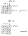
- FIGS. 12A and 12B illustrate a case in which a coding target block is a 4x4 block of a luminance signal and vertical prediction (prediction mode 0) is used.
- the luminance signal will be assumed in the following description.
- a pixel value of X in the upper-left block, pixel values of A, B, C, and D in the upper block, pixel values of E, F, G, and H in the upper-right block, and pixel values of I, J, K, and L in the left block are used in prediction.
- prediction mode 0 is prediction in a vertical direction
- a value (73) of A is copied in four adjacent pixels just thereunder (a pixel value of a reference pixel is copied).
- a value (79) of B, a value (86) of C, and a value (89) of D are each copied in four adjacent pixels just thereunder.
- prediction pixel values of the coding target block are as illustrated in FIG. 12B .
- a value of 128 is assigned or a value of an adjacent pixel is assigned, thereby prediction is possible.
- a block including a top row of the frame it is always impossible to refer to nine pixels from X to H, and thus the value of 128 is used.
- prediction pixels are generated by assigning the value of D to E, F, G, and H.
- Non-Patent Document 1 Sakae Okubo, Shinya Kadono, Yoshihiro Kikuchi, and Teruhiko Suzuki: "H.264/AVC Textbook (Third revised edition),” Impress R&D, pp. 110-116, 2009
- a reference pixel value is a pixel value at a decimal pixel position.
- an interpolation process using a bilinear filter of two taps is used. This filter uses fixed values as a tap length and filter coefficients regardless of coding conditions (quantization step size and the like).
- the reference pixel value is a decoded pixel value positioned in the vicinity of a block of interest, its characteristic is varied in accordance with the coding conditions.
- there is room for improvement in terms of enhancement in coding efficiency because the variation of the characteristic of the reference pixel value in accordance with the coding conditions is not sufficiently considered.
- the present invention has been made in view of the above-described circumstances, and an object thereof is to reduce an intra-prediction error and establish a highly efficient intra-coding method by paying attention to a reference pixel for use in intra-prediction and introducing an adaptive reference pixel generating process in accordance with coding conditions.
- intra-prediction block a region in which coding is performed using intra-prediction
- intra-reference pixel a reference pixel to be used in the intra-prediction
- the reference pixel value of the intra-prediction is generated based on adaptive selection of a filter to thereby reduce an intra-prediction residual.
- an intra-reference pixel region a region in which an intra-reference pixel is present is identified for a coding target intra-prediction block.
- the intra-reference pixel is a pixel in the vicinity of the intra-prediction block and it is determined in accordance with a size of the intra-prediction block and an intra-prediction mode.
- FIGS. 1A to 1C illustrate examples of intra-reference pixels.
- FIG. 1A illustrates an example of intra-reference pixels when the intra-prediction mode is prediction in a vertical direction
- FIG. 1B illustrates an example of intra-reference pixels when the intra-prediction mode is prediction in a horizontal direction.
- a square region corresponds to a pixel.
- P0 represents a pixel within a coding target block
- P1 represents a coded pixel
- P2 and P3 represent intra-reference pixels for pixel groups within the coding target block.
- the reference pixel differs depending on the intra-prediction mode.
- a region in which intra-reference pixels necessary to implement all the prepared intra-prediction modes are present is referred to as an intra-reference pixel region.
- An example of the intra-reference pixel region is illustrated in FIG. 1C .
- intra-reference pixels are generated by performing an interpolation process on pixel values within the intra-reference pixel region.
- a filter to be used in interpolation is adaptively selected based on coding parameters having an influence on characteristics of a decoded picture to thereby reduce an intra-prediction error.
- an interpolation filter of a shorter tap length is selected when a size of the intra-prediction block is larger and an interpolation filter of a longer tap length is selected when a quantization parameter of the intra-prediction block is smaller.
- the size of the intra-prediction block is decreased, it is likely to be within a region having complex texture and the undulation in the nature of intra-reference pixels is likely to be rich, and thus more flexible prediction pixels are likely to be generated by changing a tap length/shape of the filter.
- the distance from the reference pixel to the prediction target pixel becomes small, it is possible to expect the effect of reduction in prediction error energy by correcting the interpolation filter for diagonal intra-prediction.
- a tap length of an interpolation filter necessary for generating a reference pixel of intra-prediction is set based on one or both of a size of a block which is a processing unit of coding, transform, or prediction and a quantization parameter of the block for the reference pixel; a filtering process which generates the reference pixel is performed using the interpolation filter corresponding to the set tap length; an intra-prediction signal corresponding to a designated intra-prediction mode is generated using the generated reference pixel; an intra-prediction residual signal representing a difference between the generated intra-prediction signal and the original signal is generated; and the intra-prediction residual signal is encoded.
- a prediction residual signal also referred to as a prediction error signal
- an intra-prediction residual signal, an intra-prediction mode, and a size of an intra-prediction block in an input encoded stream are decoded; a reference pixel of intra-prediction is identified based on the intra-prediction mode and the size of the intra-prediction block; a tap length of an interpolation filter necessary for generating the reference pixel of the intra-prediction is set based on one or both of a size of a block which is a processing unit of coding, transform, or prediction and a quantization parameter of the block for the reference pixel; a filtering process which generates the reference pixel is performed using the interpolation filter corresponding to the set tap length; an intra-prediction signal corresponding to the decoded intra-prediction mode is generated using the generated reference pixel; and a decoded signal of
- the tap length of the interpolation filter when the tap length of the interpolation filter is set, if the size of the block is less than or equal to a threshold value, the tap length may be set to be longer than when the size of the block is greater than the threshold value.
- the tap length may be set to be longer than when the quantization step size is greater than the threshold value.
- the present invention is technology related to intra-prediction processing units (101 of FIG. 2 and 202 of FIG. 3 ) in a moving-picture encoding apparatus ( FIG. 2 ) and a moving-picture decoding apparatus ( FIG. 3 ). These intra-prediction processing units perform a process common to the encoding apparatus and the decoding apparatus.
- FIG. 2 is a diagram illustrating a configuration example of the moving-picture encoding apparatus to which the present invention is applied.
- the intra-prediction processing unit 101 in a moving-picture encoding apparatus 100 is a portion different from the conventional technology, and the other portions are similar to configurations of the conventional general moving-picture encoding apparatus used as an encoder in H.264/AVC and the like.
- the moving-picture encoding apparatus 100 receives an input of an encoding target video signal, divides a frame of the input video signal into blocks, performs encoding for every block, and outputs its bit stream as an encoded stream.
- a prediction residual signal generating unit 103 calculates a difference between the input video signal and a prediction signal which is an output of the intra-prediction processing unit 101 or an inter-prediction processing unit 102, and outputs it as a prediction residual signal.
- a transform processing unit 104 performs an orthogonal transform such as a discrete cosine transform (DCT) on the prediction residual signal to output transform coefficients.
- a quantization processing unit 105 quantizes the transform coefficients and outputs quantized transform coefficients.
- An entropy encoding processing unit 113 performs entropy encoding on the quantized transform coefficients and outputs a resultant signal as the encoded stream.
- DCT discrete cosine transform
- the quantized transform coefficients are also input to an inverse quantization processing unit 106 in which the quantized transform coefficients are subjected to inverse quantization.
- An inverse transform processing unit 107 performs an inverse orthogonal transform on transform coefficients which are output from the inverse quantization processing unit 106 and outputs a decoded prediction residual signal.
- a decoded signal generating unit 108 generates a decoded signal of an encoded encoding target block by adding the prediction signal which is the output of the intra-prediction processing unit 101 or the inter-prediction processing unit 102 to the decoded prediction residual signal. Because the intra-prediction processing unit 101 or the inter-prediction processing unit 102 uses the decoded signal as a reference picture, the decoded signal is stored in a frame memory 109.
- an in-loop filtering processing unit 110 receives an input of a picture stored in the frame memory 109 and performs a filtering process of reducing coding distortion, and a picture subjected to the filtering process is used as the reference picture.
- Information about the prediction mode and the like set in the intra-prediction processing unit 101 is stored in an intra-prediction information storage unit 112, is then entropy-encoded in the entropy encoding processing unit 113, and a resultant signal is output as the encoded stream.
- Information about a motion vector and the like set in the inter-prediction processing unit 102 is stored in an inter-prediction information storage unit 111, is then entropy-encoded in the entropy encoding processing unit 113, and a resultant signal is output as the encoded stream.
- FIG. 3 is a diagram illustrating a configuration example of the moving-picture decoding apparatus to which the present invention is applied.
- the intra-prediction processing unit 202 in a moving-picture decoding apparatus 200 is a portion different from the conventional technology, and the other portions are similar to configurations of the conventional general moving-picture decoding apparatus used as a decoder in H.264/AVC and the like.
- the moving-picture decoding apparatus 200 receives an input of the encoded stream encoded by the moving-picture encoding apparatus 100 illustrated in FIG. 2 , and performs decoding thereon to output a video signal of decoded pictures.
- an entropy decoding processing unit 201 receives the input of the encoded stream, entropy-decodes quantized transform coefficients of a decoding target block, and decodes information about intra-prediction and information about inter-prediction.
- the decoded result of the information about the inter-prediction is stored in an inter-prediction information storage unit 209, and the decoded result of the information about the intra-prediction is stored in an intra-prediction information storage unit 210.
- An inverse quantization processing unit 204 receives an input of the quantized transform coefficients and performs inverse quantization thereon to output decoded transform coefficients.
- An inverse transform processing unit 205 applies an inverse orthogonal transform on the decoded transform coefficients to output a decoded prediction residual signal.
- a decoded signal generating unit 206 generates a decoded signal of the decoding target block by adding a prediction signal which is an output of the intra-prediction processing unit 202 or an inter-prediction processing unit 203 to the decoded prediction residual signal. Because the intra-prediction processing unit 202 or the inter-prediction processing unit 203 uses the decoded signal as a reference picture, the decoded signal is stored in a frame memory 207.
- an in-loop filtering processing unit 208 receives an input of a picture stored in the frame memory 207 and performs a filtering process of reducing coding distortion, and a picture subjected to the filtering process is used as the reference picture. Ultimately, the picture subjected to the filtering process is output as a video signal.
- the present embodiment is technology related to an intra-prediction process in the intra-prediction processing unit 101 of FIG. 2 or the intra-prediction processing unit 202 of FIG. 3 .
- FIG. 4 illustrates a configuration example of the intra-prediction processing units.
- An intra-prediction processing unit illustrated in FIG. 4 performs a common process in the moving-picture encoding apparatus 100 and the moving-picture decoding apparatus 200.
- a block position identifying unit 301 identifies a position of an intra-prediction block within a frame.
- a reference pixel generating unit 302 receives inputs of the intra-prediction mode and the position of the intra-prediction block within the frame, and generates intra-reference pixels for the block.
- An intra-prediction value generating unit 303 receives inputs of the intra-prediction mode and the intra-reference pixels and outputs an intra-prediction value by performing prediction corresponding to the intra-prediction mode.
- FIG. 5 is a flowchart of the intra-prediction process to be executed by the intra-prediction processing unit illustrated in FIG. 4 .
- step S101 a position of an intra-prediction block within a frame is identified.
- step S102 an intra-prediction mode and the position of the intra-prediction block within the frame are input, and intra-reference pixels for the block are generated.
- step S103 the intra-prediction mode and the intra-reference pixels are input, an intra-prediction value is generated by performing prediction corresponding to the intra-prediction mode, and the intra-prediction value is output.
- FIG. 6 illustrates the first configuration example of the reference pixel generating unit 302 in the intra-prediction processing unit illustrated in FIG. 4 .
- the reference pixel generating unit 302 performs an intra-reference pixel generating process using the following configuration.
- a decoded pixel value storage unit 501 stores decoded pixel values necessary to generate a reference pixel.
- a filter for noise reduction such as a low pass filter may be applied to the decoded pixel values as in H.264/AVC
- filtered decoded pixel values may be stored.
- this filter performs a process such as (X+2 ⁇ A+B) >> 2 or (A+2xB+C) >> 2 (where >> represents an operation of shifting bits to the right) rather than directly copying the value of A in FIG. 12A .
- a decoded pixel value reading unit 502 receives an input of the intra-prediction mode and reads decoded pixel values stored in the decoded pixel value storage unit 501 in accordance with the intra-prediction mode.
- a prediction mode determining unit 503 receives inputs of the intra-prediction mode and the decoded pixel values read by the decoded pixel value reading unit 502, determines whether interpolation of a decimal pixel position is necessary to generate a reference pixel for use in the prediction mode, and selects a reference pixel value necessary for intra-prediction from the decoded pixel positions if the interpolation is unnecessary. Otherwise, the process moves to that of an intra-prediction block size reading unit 505.
- an intra-prediction block size storage unit 504, the intra-prediction block size reading unit 505, and an interpolation filter selecting unit 506 represented by a dotted-line frame in FIG. 6 are portions different from the conventional technology.
- the intra-prediction block size storage unit 504 stores a size of an intra-prediction target block (intra-prediction block).
- intra-prediction block there are three types of 4x4, 8x8, and 16x16 as the block size. It is to be noted that the present embodiment is not limited to these sizes; for example, the block size such as 32x32 may be targeted.
- the intra-prediction block size reading unit 505 reads the size of the intra-prediction block stored in the intra-prediction block size storage unit 504.
- the interpolation filter selecting unit 506 receives inputs of the size of the intra-prediction block and the intra-prediction mode, and selects an interpolation filter to be used to generate the intra-reference pixel in accordance with the size of the intra-prediction block and the intra-prediction mode.
- a threshold value assigned in advance is read, an interpolation filter of a shorter tap length is selected if the size of the intra-prediction block is larger and an interpolation filter of a longer tap length is selected if the size of the intra-prediction block is smaller.
- the block size of the threshold value is 8x8 and the block size of the intra-prediction is a size larger than 8x8, an interpolation filter having a tap length of 2 is selected; when the block size is less than or equal to 8x8, an interpolation filter having a tap length of 4 is selected (a tap length greater than or equal to 4, such as 6 or 8 is also possible).
- there may be a plurality of threshold values For example, when two types of threshold values are 8x8 and 16x16, the tap length may be set to 6 for 4x4 and 8x8, the tap length may be set to 4 for 16x16, and the tap length may be set to 2 for a size greater than 16 ⁇ 16.
- the size of the intra-prediction block for use in the prediction process, it is possible to read sizes of blocks of a coding process and a transform process including an in-process block and set a tap length from the sizes using a threshold value assigned in advance.
- the tap length is set by reading a table assigned in advance and reading a tap length corresponding to an input block size in accordance with the block size. It is assumed that block sizes and tap lengths are associated with each other in the above-described table, a shorter tap length is set as the block size becomes larger, and a longer tap length is set as the block size becomes smaller.
- the interpolation can be performed as follows using a filter having coefficients of [-5/64, 55/64, 17/64, -3/64].
- P ⁇ i + 1 / 8 , j P ⁇ i - 1 , j ⁇ - 5 / 64 + P i j ⁇ 55 / 64 + P ⁇ i + 1 , j ⁇ 17 / 64 + P ⁇ i + 2 , j ⁇ - 3 / 64
- the general interpolation filter for use in coding and picture processing can be similarly applied to the present embodiment.
- the reference pixel value generating unit 507 receives inputs of the intra-prediction mode, the decoded pixel values read by the decoded pixel value reading unit 502, and the interpolation filter selected by the interpolation filter selecting unit 506, and performs an interpolation process using the selected interpolation filter to generate a reference pixel value necessary for intra-prediction.
- the conventional technology is different from the present embodiment in that only the intra-prediction mode output by the prediction mode determining unit 503 is input and the interpolation filter to be used to generate the intra-reference pixel is selected in accordance with the intra-prediction mode without performing the reading of the intra-prediction block size and the like.
- FIG. 7 is a flowchart of the intra-reference pixel generating process (example 1).
- the first example of the intra-reference pixel generating process to be executed by the reference pixel generating unit 302 illustrated in FIG. 4 will be described in detail with reference to FIG. 7 .
- step S201 an intra-prediction mode is read.
- step S202 the intra-prediction mode is input and decoded pixel values necessary for generating a reference pixel are read.
- step S203 the intra-prediction mode is input, and it is determined whether interpolation of a decimal pixel position is necessary to generate the reference pixel for use in the prediction mode. If the interpolation is necessary, the process moves to step S205. Otherwise, the process moves to step S204.
- step S204 the intra-prediction mode and the decoded pixel values read in step S202 are input, a reference pixel value necessary for intra-prediction is selected from the decoded pixel values, and the selected reference pixel value is set as an intra-reference pixel.
- step S205 the size of the intra-prediction target block (intra-prediction block) is read.
- intra-prediction block there are three types of 4x4, 8x8, and 16x16 as the block size, but block sizes greater than or equal to those or other block sizes such as mxn (m and n are different positive integer values) may be provided.
- step S206 the size of the intra-prediction block and the intra-prediction mode are input and an interpolation filter to be used to generate the intra-reference pixel is selected in accordance with the size of the intra-prediction block and the intra-prediction mode.
- an interpolation filter of a shorter tap length is selected when the size of the intra-prediction block is larger, and an interpolation filter of a longer tap length is selected when the size of the intra-prediction block is smaller.
- step S207 the intra-prediction mode, the decoded pixel values read in step S202, and the interpolation filter selected in step S206 are input and an interpolation process using the interpolation filter is performed to generate a reference pixel value necessary for intra-prediction.
- a difference of FIG. 7 from the conventional technology is portions of steps S205 and S206 represented by a dotted-line frame.
- the intra-prediction mode is input and the interpolation filter to be used to generate the intra-reference pixel is selected in accordance with only the intra-prediction mode.
- the present embodiment is different from the conventional technology in that the block size of the intra-prediction and the intra-prediction mode are read and the interpolation filter to be used to generate the intra-reference pixel is selected in accordance with the size of the intra-prediction block and the intra-prediction mode.
- the size of the intra-prediction block for use in the prediction process, it is possible to read sizes of blocks of a coding process and a transform process including an in-process block, and similarly set a tap length from the sizes using a threshold value assigned in advance.
- FIG. 8 illustrates the second configuration example of the reference pixel generating unit 302 in the intra-prediction processing unit illustrated in FIG. 4 .
- the reference pixel generating unit 302 can perform the intra-reference pixel generating process using the configuration illustrated in FIG. 8 .
- FIG. 8 processes to be performed by a decoded pixel value storage unit 511, a decoded pixel value reading unit 512, a prediction mode determining unit 513, and a reference pixel value generating unit 517 are similar to those described with reference to FIG. 6 .
- a quantization step size storage unit 514 stores a parameter (referred to as a QP parameter) representing a quantization step size to be used in quantization of an intra-prediction target block (intra-prediction block).
- a QP parameter a parameter representing a quantization step size to be used in quantization of an intra-prediction target block (intra-prediction block).
- a quantization step size reading unit 515 reads the QP parameter stored in the quantization step size storage unit 514.
- An interpolation filter selecting unit 516 receives inputs of the QP parameter and the intra-prediction mode and selects an interpolation filter to be used to generate an intra-reference pixel in accordance with the QP parameter and the intra-prediction mode. In particular, in the selection of the interpolation filter, an interpolation filter of a longer tap length is selected when the QP parameter is smaller in accordance with predetermined correspondence information between QP parameters and tap lengths.
- FIG. 9 is a flowchart of the intra-reference pixel generating process (example 2).
- the second example of the intra-reference pixel generating process to be executed by the reference pixel generating unit 302 illustrated in FIG. 8 will be described with reference to FIG. 9 .
- steps S211 to S214 and S217 illustrated in FIG. 9 are similar to those to be performed in steps S201 to S204 and S207 described with reference to FIG. 7 .
- a parameter (referred to as a QP parameter) representing a quantization step size to be used to quantize an intra-prediction target block (intra-prediction block) is read.
- step S216 the QP parameter and the intra-prediction mode are input and an interpolation filter to be used to generate an intra-reference pixel is selected in accordance with the QP parameter and the intra-prediction mode.
- an interpolation filter of a longer tap length is selected when the QP parameter is smaller compared to when the QP parameter is larger.
- the interpolation filter is selected in accordance with the size of the intra-prediction block and an example in which the interpolation filter is selected in accordance with the quantization parameter have been described above, it is possible to set the tap length of the interpolation filter in consideration of both of them. For example, when the magnitudes of quantization parameters of intra-prediction blocks are the same, an interpolation filter of a shorter tap length is set for an intra-prediction block having a larger size and an interpolation filter of a longer tap length is set for an intra-prediction block having a smaller size.
- an interpolation filter of a longer tap length is set for a smaller quantization parameter and an interpolation filter of a shorter tap length is set for a larger quantization parameter.
- an implementation which adaptively selects an appropriate interpolation filter is also possible by generating, for all the intra-prediction modes, tables which store correspondence information representing which interpolation filter of which tap length is to be used for a combination of a size of each intra-prediction block and a quantization parameter value in advance and selecting the interpolation filter based on the tables.
- the above moving-picture encoding and decoding processes can be implemented by a computer and a software program, and the program can be recorded on a computer-readable recording medium and provided through a network.
- FIG. 10 illustrates a configuration example of hardware in which the moving-picture encoding apparatus is configured by a computer and a software program.
- the present system has a configuration in which a central processing unit (CPU) 700 which executes the program, a memory 701 such as a random access memory (RAM) which stores the program and data accessed by the CPU 700, a video signal input unit 702 (which may be a storage unit which stores a video signal using a disk apparatus or the like) which inputs an encoding target video signal from a camera or the like, a program storage apparatus 703 which stores a moving-picture encoding program 704 which is the software program for causing the CPU 700 to execute the encoding process described in the embodiment of the present invention, and an encoded stream output unit 705 (which may be a storage unit which stores an encoded stream using a disk apparatus or the like) which outputs an encoded stream generated by the CPU 700 executing the moving-picture encoding program 704 loaded to the memory 701, for example, via
- FIG. 11 illustrates a configuration example of hardware in which the moving-picture decoding apparatus is configured by a computer and a software program.
- the present system has a configuration in which a CPU 800 which executes the program, a memory 801 such as a RAM which stores the program and data accessed by the CPU 800, an encoded stream input unit 802 (which may be a storage unit which stores an encoded stream using a disk apparatus or the like) which receives an input of an encoded stream encoded by the moving-picture encoding apparatus in accordance with the present technique, a program storage apparatus 803 which stores a moving-picture decoding program 804 which is the software program for causing the CPU 800 to execute the decoding process described in the embodiment of the present invention, and a decoded video data output unit 805 (which may be a storage unit which stores decoded video data using a disk apparatus or the like) which outputs, to a reproduction apparatus and the like, decoded video obtained by the CPU 800 executing the moving-picture decoding program 804
- the present invention can be applied to encoding and decoding of a picture using intra-prediction.
- it is possible to generate an intra-reference pixel value close to an original signal at a prediction target pixel position and reduce a bit amount through reduction in intra-prediction error energy.
Abstract
Description
- The present invention relates to a highly efficient encoding/decoding method of a picture signal, and more particularly to technology for encoding or decoding a picture using intra-prediction.
- Priority is claimed on Japanese Patent Application No.
2011-243041, filed November 7, 2011 - Algorithms of moving-picture coding are classified roughly into inter-frame coding (inter-coding) and intra-frame coding (intra-coding). Inter-frame coding is an approach which compresses information using correlation in a time-domain within a moving picture. A representative example thereof is inter-frame prediction using motion compensation. In contrast, intra-frame coding is an approach which compresses information using a correlation within a frame. Joint Photographic Experts Group (JPEG) and Moving Picture Experts Group (MPEG)-2 employ an approach using a discrete cosine transform (DCT) and JPEG2000 employs an approach using a discrete wavelet transform.
- In H.264/AVC, prediction in a space-domain is performed in addition to the above-described transform coding (see Non-Patent Document 1). Prediction in a space-domain is intra-frame prediction in which prediction is performed within the same frame in a space dimension. Intra-frame prediction is performed in units of blocks; in H.264/AVC, three types of block sizes (4x4, 8x8, and 16x16) are available for a luminance signal. In addition, it is possible to select a plurality of prediction modes for each block size. In the case of the 4x4 and 8x8 block sizes, nine types of modes are prepared; in the case of the 16x16 block size, four types of modes are prepared. Only the 8×8 block size is available for a chrominance signal and a prediction direction is the same as that of a 16×16 block for a luminance signal. However, the association between mode numbers and the prediction directions is different.
- For any one of these block sizes and modes, pixels generated by intra-frame prediction are obtained by, without exception, copying the same values as values of pixels closest to a coding target block on an adjacent block without changing the values of the closest pixels.
- As a specific example,
FIGS. 12A and 12B illustrate a case in which a coding target block is a 4x4 block of a luminance signal and vertical prediction (prediction mode 0) is used. In addition, unless otherwise noted, the luminance signal will be assumed in the following description. As illustrated inFIG. 12A , with respect to the coding target block, a pixel value of X in the upper-left block, pixel values of A, B, C, and D in the upper block, pixel values of E, F, G, and H in the upper-right block, and pixel values of I, J, K, and L in the left block are used in prediction. Because the prediction mode 0 is prediction in a vertical direction, a value (73) of A is copied in four adjacent pixels just thereunder (a pixel value of a reference pixel is copied). Hereinafter, likewise, a value (79) of B, a value (86) of C, and a value (89) of D are each copied in four adjacent pixels just thereunder. As a result, in the prediction mode 0, prediction pixel values of the coding target block are as illustrated inFIG. 12B . - Depending on a position at which a coding target block is present, there may be no block to be referred to. In this case, a value of 128 is assigned or a value of an adjacent pixel is assigned, thereby prediction is possible. For example, with respect to a block including a top row of the frame, it is always impossible to refer to nine pixels from X to H, and thus the value of 128 is used. In addition, when there is an upper-left block and an upper block but there is no upper-right block, prediction pixels are generated by assigning the value of D to E, F, G, and H.
- As an approach for improving intra-prediction of H.264/AVC, a technique of supporting 33 prediction directions obtained by
sub-dividing 8 prediction directions has been proposed. This technique is aimed at reducing a prediction error (also referred to as a prediction residual) due to the roughness of granularity in a prediction direction. - Non-Patent Document 1: Sakae Okubo, Shinya Kadono, Yoshihiro Kikuchi, and Teruhiko Suzuki: "H.264/AVC Textbook (Third revised edition)," Impress R&D, pp. 110-116, 2009
- In the above-described intra-prediction, the generation of the reference pixel significantly affects prediction performance. In the case of diagonal prediction (prediction other than horizontal prediction, vertical prediction, and DC prediction), a reference pixel value is a pixel value at a decimal pixel position. In the generation of the pixel value, an interpolation process using a bilinear filter of two taps is used. This filter uses fixed values as a tap length and filter coefficients regardless of coding conditions (quantization step size and the like). However, because the reference pixel value is a decoded pixel value positioned in the vicinity of a block of interest, its characteristic is varied in accordance with the coding conditions. Thus, in the conventional intra-prediction, there is room for improvement in terms of enhancement in coding efficiency because the variation of the characteristic of the reference pixel value in accordance with the coding conditions is not sufficiently considered.
- The present invention has been made in view of the above-described circumstances, and an object thereof is to reduce an intra-prediction error and establish a highly efficient intra-coding method by paying attention to a reference pixel for use in intra-prediction and introducing an adaptive reference pixel generating process in accordance with coding conditions.
- First, terms will be defined. Hereinafter, a region in which coding is performed using intra-prediction is referred to as an intra-prediction block, and a reference pixel to be used in the intra-prediction is referred to as an intra-reference pixel.
- In the present invention, for the intra-reference pixel, the reference pixel value of the intra-prediction is generated based on adaptive selection of a filter to thereby reduce an intra-prediction residual.
- First, a region (hereinafter referred to as an intra-reference pixel region) in which an intra-reference pixel is present is identified for a coding target intra-prediction block. The intra-reference pixel is a pixel in the vicinity of the intra-prediction block and it is determined in accordance with a size of the intra-prediction block and an intra-prediction mode.
-
FIGS. 1A to 1C illustrate examples of intra-reference pixels.FIG. 1A illustrates an example of intra-reference pixels when the intra-prediction mode is prediction in a vertical direction, andFIG. 1B illustrates an example of intra-reference pixels when the intra-prediction mode is prediction in a horizontal direction. - In
FIGS. 1A to 1C , a square region corresponds to a pixel. In addition, P0 represents a pixel within a coding target block, P1 represents a coded pixel, and P2 and P3 represent intra-reference pixels for pixel groups within the coding target block. In this manner, the reference pixel differs depending on the intra-prediction mode. A region in which intra-reference pixels necessary to implement all the prepared intra-prediction modes are present is referred to as an intra-reference pixel region. An example of the intra-reference pixel region is illustrated inFIG. 1C . - In the case of diagonal intra-prediction (prediction other than horizontal-direction prediction, vertical-direction prediction, and DC prediction), intra-reference pixels are generated by performing an interpolation process on pixel values within the intra-reference pixel region. In this generation, a filter to be used in interpolation is adaptively selected based on coding parameters having an influence on characteristics of a decoded picture to thereby reduce an intra-prediction error.
- In the selection of the interpolation filter, an interpolation filter of a shorter tap length is selected when a size of the intra-prediction block is larger and an interpolation filter of a longer tap length is selected when a quantization parameter of the intra-prediction block is smaller.
- This is for the following reasons. In general, when the size of the intra-prediction block becomes larger, there is a higher possibility that texture is flat and the nature of the intra-reference pixels can be constant. It is likely that it is not necessary to use a long tap length and it is sufficient to use a short tap length. Furthermore, because a distance from the reference pixel to a prediction target pixel is large (in particular, a distance from the reference pixel to a pixel closer to a lowest and rightmost pixel of the coding target block becomes greater and this tendency is remarkable as a block size increases), it is difficult to expect the effect of reduction in prediction error energy even when an interpolation filter for diagonal intra-prediction is corrected. In contrast, when the size of the intra-prediction block is decreased, it is likely to be within a region having complex texture and the undulation in the nature of intra-reference pixels is likely to be rich, and thus more flexible prediction pixels are likely to be generated by changing a tap length/shape of the filter. In addition, because the distance from the reference pixel to the prediction target pixel becomes small, it is possible to expect the effect of reduction in prediction error energy by correcting the interpolation filter for diagonal intra-prediction.
- In addition, when the quantization parameter of the intra-prediction block is small, a decoded picture often has a complex pattern and an interpolation filter of a long tap length is appropriate to generate reference pixels with high prediction precision. In contrast, because the picture is often flat when the quantization parameter of the intra-prediction block is large, it is possible to maintain prediction precision even with an interpolation filter of a short tap length.
- Specifically, in accordance with the present invention, in picture encoding for generating a prediction signal using spatial inter-pixel prediction and encoding a picture using a prediction residual signal (also referred to as a prediction error signal) which is a difference between the prediction signal and an original signal, a tap length of an interpolation filter necessary for generating a reference pixel of intra-prediction is set based on one or both of a size of a block which is a processing unit of coding, transform, or prediction and a quantization parameter of the block for the reference pixel; a filtering process which generates the reference pixel is performed using the interpolation filter corresponding to the set tap length; an intra-prediction signal corresponding to a designated intra-prediction mode is generated using the generated reference pixel; an intra-prediction residual signal representing a difference between the generated intra-prediction signal and the original signal is generated; and the intra-prediction residual signal is encoded.
- In addition, in accordance with the present invention, in picture decoding for generating a prediction signal using spatial inter-pixel prediction and decoding a picture using a prediction residual signal which is a difference between the prediction signal and an original signal, an intra-prediction residual signal, an intra-prediction mode, and a size of an intra-prediction block in an input encoded stream are decoded; a reference pixel of intra-prediction is identified based on the intra-prediction mode and the size of the intra-prediction block; a tap length of an interpolation filter necessary for generating the reference pixel of the intra-prediction is set based on one or both of a size of a block which is a processing unit of coding, transform, or prediction and a quantization parameter of the block for the reference pixel; a filtering process which generates the reference pixel is performed using the interpolation filter corresponding to the set tap length; an intra-prediction signal corresponding to the decoded intra-prediction mode is generated using the generated reference pixel; and a decoded signal of a decoding target region is generated using the generated intra-prediction signal and the intra-prediction residual signal.
- In addition, in the picture encoding or the picture decoding, when the tap length of the interpolation filter is set, if the size of the block is less than or equal to a threshold value, the tap length may be set to be longer than when the size of the block is greater than the threshold value. Alternatively, if a quantization step size represented by the quantization parameter of the block is less than or equal to a threshold value, the tap length may be set to be longer than when the quantization step size is greater than the threshold value.
- In accordance with the present invention, it is possible to generate an intra-reference pixel value close to an original signal at a prediction target pixel position. As a result, it is possible to reduce a bit amount through reduction in intra-prediction error energy.
-
-
FIG. 1A is a diagram illustrating an example of intra-reference pixels. -
FIG. 1B is a diagram illustrating an example of intra-reference pixels. -
FIG. 1C is a diagram illustrating an example of intra-reference pixels. -
FIG. 2 is a diagram illustrating a configuration example of a moving-picture encoding apparatus to which the present invention is applied. -
FIG. 3 is a diagram illustrating a configuration example of a moving-picture decoding apparatus to which the present invention is applied. -
FIG. 4 is a diagram illustrating a configuration example of an intra-prediction processing unit. -
FIG. 5 is a flowchart of an intra-prediction process. -
FIG. 6 is a diagram illustrating a first configuration example of a reference pixel generating unit. -
FIG. 7 is a flowchart of an intra-reference pixel generating process (example 1). -
FIG. 8 is a diagram illustrating a second configuration example of the reference pixel generating unit. -
FIG. 9 is a flowchart of an intra-reference pixel generating process (example 2). -
FIG. 10 is a diagram illustrating a configuration example of a system when a moving-picture encoding apparatus is implemented using a computer and a software program. -
FIG. 11 is a diagram illustrating a configuration example of a system when a moving-picture decoding apparatus is implemented using a computer and a software program. -
FIG. 12A is a diagram illustrating an example of an intra-prediction pixel generation method in conventional intra-frame prediction. -
FIG. 12B is a diagram illustrating an example of the intra-prediction pixel generation method in the conventional intra-frame prediction. - The present invention is technology related to intra-prediction processing units (101 of
FIG. 2 and 202 ofFIG. 3 ) in a moving-picture encoding apparatus (FIG. 2 ) and a moving-picture decoding apparatus (FIG. 3 ). These intra-prediction processing units perform a process common to the encoding apparatus and the decoding apparatus. - Hereinafter, examples of the moving-picture encoding apparatus and the moving-picture decoding apparatus to which the present invention is applied will first be shown and then a detailed description of the intra-prediction processing units improved by the present invention will be given.
-
FIG. 2 is a diagram illustrating a configuration example of the moving-picture encoding apparatus to which the present invention is applied. In the present embodiment, in particular, theintra-prediction processing unit 101 in a moving-picture encoding apparatus 100 is a portion different from the conventional technology, and the other portions are similar to configurations of the conventional general moving-picture encoding apparatus used as an encoder in H.264/AVC and the like. - The moving-
picture encoding apparatus 100 receives an input of an encoding target video signal, divides a frame of the input video signal into blocks, performs encoding for every block, and outputs its bit stream as an encoded stream. To perform the encoding, a prediction residualsignal generating unit 103 calculates a difference between the input video signal and a prediction signal which is an output of theintra-prediction processing unit 101 or aninter-prediction processing unit 102, and outputs it as a prediction residual signal. Atransform processing unit 104 performs an orthogonal transform such as a discrete cosine transform (DCT) on the prediction residual signal to output transform coefficients. Aquantization processing unit 105 quantizes the transform coefficients and outputs quantized transform coefficients. An entropyencoding processing unit 113 performs entropy encoding on the quantized transform coefficients and outputs a resultant signal as the encoded stream. - On the other hand, the quantized transform coefficients are also input to an inverse
quantization processing unit 106 in which the quantized transform coefficients are subjected to inverse quantization. An inversetransform processing unit 107 performs an inverse orthogonal transform on transform coefficients which are output from the inversequantization processing unit 106 and outputs a decoded prediction residual signal. - A decoded
signal generating unit 108 generates a decoded signal of an encoded encoding target block by adding the prediction signal which is the output of theintra-prediction processing unit 101 or theinter-prediction processing unit 102 to the decoded prediction residual signal. Because theintra-prediction processing unit 101 or theinter-prediction processing unit 102 uses the decoded signal as a reference picture, the decoded signal is stored in aframe memory 109. It is to be noted that when the reference picture is referred to in theinter-prediction processing unit 102, an in-loopfiltering processing unit 110 receives an input of a picture stored in theframe memory 109 and performs a filtering process of reducing coding distortion, and a picture subjected to the filtering process is used as the reference picture. - Information about the prediction mode and the like set in the
intra-prediction processing unit 101 is stored in an intra-predictioninformation storage unit 112, is then entropy-encoded in the entropyencoding processing unit 113, and a resultant signal is output as the encoded stream. Information about a motion vector and the like set in theinter-prediction processing unit 102 is stored in an inter-predictioninformation storage unit 111, is then entropy-encoded in the entropyencoding processing unit 113, and a resultant signal is output as the encoded stream. -
FIG. 3 is a diagram illustrating a configuration example of the moving-picture decoding apparatus to which the present invention is applied. In the present embodiment, in particular, theintra-prediction processing unit 202 in a moving-picture decoding apparatus 200 is a portion different from the conventional technology, and the other portions are similar to configurations of the conventional general moving-picture decoding apparatus used as a decoder in H.264/AVC and the like. - The moving-
picture decoding apparatus 200 receives an input of the encoded stream encoded by the moving-picture encoding apparatus 100 illustrated inFIG. 2 , and performs decoding thereon to output a video signal of decoded pictures. For this decoding, an entropydecoding processing unit 201 receives the input of the encoded stream, entropy-decodes quantized transform coefficients of a decoding target block, and decodes information about intra-prediction and information about inter-prediction. The decoded result of the information about the inter-prediction is stored in an inter-predictioninformation storage unit 209, and the decoded result of the information about the intra-prediction is stored in an intra-predictioninformation storage unit 210. - An inverse
quantization processing unit 204 receives an input of the quantized transform coefficients and performs inverse quantization thereon to output decoded transform coefficients. An inversetransform processing unit 205 applies an inverse orthogonal transform on the decoded transform coefficients to output a decoded prediction residual signal. A decodedsignal generating unit 206 generates a decoded signal of the decoding target block by adding a prediction signal which is an output of theintra-prediction processing unit 202 or aninter-prediction processing unit 203 to the decoded prediction residual signal. Because theintra-prediction processing unit 202 or theinter-prediction processing unit 203 uses the decoded signal as a reference picture, the decoded signal is stored in aframe memory 207. It is to be noted that when theinter-prediction processing unit 203 refers to the reference picture, an in-loopfiltering processing unit 208 receives an input of a picture stored in theframe memory 207 and performs a filtering process of reducing coding distortion, and a picture subjected to the filtering process is used as the reference picture. Ultimately, the picture subjected to the filtering process is output as a video signal. - The present embodiment is technology related to an intra-prediction process in the
intra-prediction processing unit 101 ofFIG. 2 or theintra-prediction processing unit 202 ofFIG. 3 . -
FIG. 4 illustrates a configuration example of the intra-prediction processing units. An intra-prediction processing unit illustrated inFIG. 4 performs a common process in the moving-picture encoding apparatus 100 and the moving-picture decoding apparatus 200. - A block
position identifying unit 301 identifies a position of an intra-prediction block within a frame. A referencepixel generating unit 302 receives inputs of the intra-prediction mode and the position of the intra-prediction block within the frame, and generates intra-reference pixels for the block. An intra-predictionvalue generating unit 303 receives inputs of the intra-prediction mode and the intra-reference pixels and outputs an intra-prediction value by performing prediction corresponding to the intra-prediction mode. -
FIG. 5 is a flowchart of the intra-prediction process to be executed by the intra-prediction processing unit illustrated inFIG. 4 . - First, in step S101, a position of an intra-prediction block within a frame is identified. Next, in step S102, an intra-prediction mode and the position of the intra-prediction block within the frame are input, and intra-reference pixels for the block are generated. Next, in step S103, the intra-prediction mode and the intra-reference pixels are input, an intra-prediction value is generated by performing prediction corresponding to the intra-prediction mode, and the intra-prediction value is output.
-
FIG. 6 illustrates the first configuration example of the referencepixel generating unit 302 in the intra-prediction processing unit illustrated inFIG. 4 . The referencepixel generating unit 302 performs an intra-reference pixel generating process using the following configuration. - A decoded pixel
value storage unit 501 stores decoded pixel values necessary to generate a reference pixel. At this time, for example, after a filter for noise reduction such as a low pass filter may be applied to the decoded pixel values as in H.264/AVC, filtered decoded pixel values may be stored. Specifically, this filter performs a process such as (X+2×A+B) >> 2 or (A+2xB+C) >> 2 (where >> represents an operation of shifting bits to the right) rather than directly copying the value of A inFIG. 12A . A decoded pixelvalue reading unit 502 receives an input of the intra-prediction mode and reads decoded pixel values stored in the decoded pixelvalue storage unit 501 in accordance with the intra-prediction mode. A predictionmode determining unit 503 receives inputs of the intra-prediction mode and the decoded pixel values read by the decoded pixelvalue reading unit 502, determines whether interpolation of a decimal pixel position is necessary to generate a reference pixel for use in the prediction mode, and selects a reference pixel value necessary for intra-prediction from the decoded pixel positions if the interpolation is unnecessary. Otherwise, the process moves to that of an intra-prediction blocksize reading unit 505. - In the present embodiment, an intra-prediction block
size storage unit 504, the intra-prediction blocksize reading unit 505, and an interpolationfilter selecting unit 506 represented by a dotted-line frame inFIG. 6 are portions different from the conventional technology. - The intra-prediction block
size storage unit 504 stores a size of an intra-prediction target block (intra-prediction block). In the case of H.264/AVC, there are three types of 4x4, 8x8, and 16x16 as the block size. It is to be noted that the present embodiment is not limited to these sizes; for example, the block size such as 32x32 may be targeted. A block size of a block other than a square shape, such as mxn (m and n are different positive integer values), may be similarly targeted. - The intra-prediction block
size reading unit 505 reads the size of the intra-prediction block stored in the intra-prediction blocksize storage unit 504. - The interpolation
filter selecting unit 506 receives inputs of the size of the intra-prediction block and the intra-prediction mode, and selects an interpolation filter to be used to generate the intra-reference pixel in accordance with the size of the intra-prediction block and the intra-prediction mode. In particular, in the selection of the interpolation filter, a threshold value assigned in advance is read, an interpolation filter of a shorter tap length is selected if the size of the intra-prediction block is larger and an interpolation filter of a longer tap length is selected if the size of the intra-prediction block is smaller. For example, when the block size of the threshold value is 8x8 and the block size of the intra-prediction is a size larger than 8x8, an interpolation filter having a tap length of 2 is selected; when the block size is less than or equal to 8x8, an interpolation filter having a tap length of 4 is selected (a tap length greater than or equal to 4, such as 6 or 8 is also possible). In addition, there may be a plurality of threshold values. For example, when two types of threshold values are 8x8 and 16x16, the tap length may be set to 6 for 4x4 and 8x8, the tap length may be set to 4 for 16x16, and the tap length may be set to 2 for a size greater than 16×16. Furthermore, instead of the size of the intra-prediction block for use in the prediction process, it is possible to read sizes of blocks of a coding process and a transform process including an in-process block and set a tap length from the sizes using a threshold value assigned in advance. - Instead of assigning the threshold value, it is possible to set the tap length by reading a table assigned in advance and reading a tap length corresponding to an input block size in accordance with the block size. It is assumed that block sizes and tap lengths are associated with each other in the above-described table, a shorter tap length is set as the block size becomes larger, and a longer tap length is set as the block size becomes smaller.
- Filter coefficients to be used when the tap length is determined can be determined, for example, as follows. Two pixels at integer positions are assumed to be P(i, j) and P(i+1,j). Here, i and j are assumed to be spatial coordinates in an x (horizontal) direction and a y (vertical) direction, respectively. Assuming that P(i+1/8, j) obtained by shifting the position of P(i, j) by a 1/8 pixel is to be interpolated and two taps are used, the interpolation can be performed as follows using a filter having coefficients of [7/8, 1/8].

- In addition, when four taps are used, the interpolation can be performed as follows using a filter having coefficients of [-5/64, 55/64, 17/64, -3/64].

- The general interpolation filter for use in coding and picture processing can be similarly applied to the present embodiment.
- The reference pixel
value generating unit 507 receives inputs of the intra-prediction mode, the decoded pixel values read by the decoded pixelvalue reading unit 502, and the interpolation filter selected by the interpolationfilter selecting unit 506, and performs an interpolation process using the selected interpolation filter to generate a reference pixel value necessary for intra-prediction. - It is to be noted that the conventional technology is different from the present embodiment in that only the intra-prediction mode output by the prediction
mode determining unit 503 is input and the interpolation filter to be used to generate the intra-reference pixel is selected in accordance with the intra-prediction mode without performing the reading of the intra-prediction block size and the like. -
FIG. 7 is a flowchart of the intra-reference pixel generating process (example 1). Hereinafter, the first example of the intra-reference pixel generating process to be executed by the referencepixel generating unit 302 illustrated inFIG. 4 will be described in detail with reference toFIG. 7 . - First, in step S201, an intra-prediction mode is read. Next, in step S202, the intra-prediction mode is input and decoded pixel values necessary for generating a reference pixel are read. In step S203, the intra-prediction mode is input, and it is determined whether interpolation of a decimal pixel position is necessary to generate the reference pixel for use in the prediction mode. If the interpolation is necessary, the process moves to step S205. Otherwise, the process moves to step S204.
- In step S204, the intra-prediction mode and the decoded pixel values read in step S202 are input, a reference pixel value necessary for intra-prediction is selected from the decoded pixel values, and the selected reference pixel value is set as an intra-reference pixel.
- In contrast, if the interpolation of the decimal pixel position is necessary, in step S205, the size of the intra-prediction target block (intra-prediction block) is read. In the case of H.264/AVC, there are three types of 4x4, 8x8, and 16x16 as the block size, but block sizes greater than or equal to those or other block sizes such as mxn (m and n are different positive integer values) may be provided.
- In step S206, the size of the intra-prediction block and the intra-prediction mode are input and an interpolation filter to be used to generate the intra-reference pixel is selected in accordance with the size of the intra-prediction block and the intra-prediction mode. In the selection of the interpolation filter, an interpolation filter of a shorter tap length is selected when the size of the intra-prediction block is larger, and an interpolation filter of a longer tap length is selected when the size of the intra-prediction block is smaller. As described above, it is possible to select the interpolation filter of the tap length set in accordance with the block size based on the threshold value or the table assigned in advance.
- In step S207, the intra-prediction mode, the decoded pixel values read in step S202, and the interpolation filter selected in step S206 are input and an interpolation process using the interpolation filter is performed to generate a reference pixel value necessary for intra-prediction.
- A difference of
FIG. 7 from the conventional technology is portions of steps S205 and S206 represented by a dotted-line frame. In the conventional technology, the intra-prediction mode is input and the interpolation filter to be used to generate the intra-reference pixel is selected in accordance with only the intra-prediction mode. The present embodiment is different from the conventional technology in that the block size of the intra-prediction and the intra-prediction mode are read and the interpolation filter to be used to generate the intra-reference pixel is selected in accordance with the size of the intra-prediction block and the intra-prediction mode. It is to be noted that instead of the size of the intra-prediction block for use in the prediction process, it is possible to read sizes of blocks of a coding process and a transform process including an in-process block, and similarly set a tap length from the sizes using a threshold value assigned in advance. -
FIG. 8 illustrates the second configuration example of the referencepixel generating unit 302 in the intra-prediction processing unit illustrated inFIG. 4 . The referencepixel generating unit 302 can perform the intra-reference pixel generating process using the configuration illustrated inFIG. 8 . - In
FIG. 8 , processes to be performed by a decoded pixelvalue storage unit 511, a decoded pixelvalue reading unit 512, a predictionmode determining unit 513, and a reference pixelvalue generating unit 517 are similar to those described with reference toFIG. 6 . - In the present embodiment, a quantization step
size storage unit 514 stores a parameter (referred to as a QP parameter) representing a quantization step size to be used in quantization of an intra-prediction target block (intra-prediction block). - A quantization step
size reading unit 515 reads the QP parameter stored in the quantization stepsize storage unit 514. An interpolationfilter selecting unit 516 receives inputs of the QP parameter and the intra-prediction mode and selects an interpolation filter to be used to generate an intra-reference pixel in accordance with the QP parameter and the intra-prediction mode. In particular, in the selection of the interpolation filter, an interpolation filter of a longer tap length is selected when the QP parameter is smaller in accordance with predetermined correspondence information between QP parameters and tap lengths. -
FIG. 9 is a flowchart of the intra-reference pixel generating process (example 2). Hereinafter, the second example of the intra-reference pixel generating process to be executed by the referencepixel generating unit 302 illustrated inFIG. 8 will be described with reference toFIG. 9 . - The processes to be performed in steps S211 to S214 and S217 illustrated in
FIG. 9 are similar to those to be performed in steps S201 to S204 and S207 described with reference toFIG. 7 . - In the present embodiment, in step S215, a parameter (referred to as a QP parameter) representing a quantization step size to be used to quantize an intra-prediction target block (intra-prediction block) is read.
- Next, in step S216, the QP parameter and the intra-prediction mode are input and an interpolation filter to be used to generate an intra-reference pixel is selected in accordance with the QP parameter and the intra-prediction mode. In the selection of the interpolation filter, an interpolation filter of a longer tap length is selected when the QP parameter is smaller compared to when the QP parameter is larger.
- Although an example in which the interpolation filter is selected in accordance with the size of the intra-prediction block and an example in which the interpolation filter is selected in accordance with the quantization parameter have been described above, it is possible to set the tap length of the interpolation filter in consideration of both of them. For example, when the magnitudes of quantization parameters of intra-prediction blocks are the same, an interpolation filter of a shorter tap length is set for an intra-prediction block having a larger size and an interpolation filter of a longer tap length is set for an intra-prediction block having a smaller size. In addition, when the sizes of intra-prediction blocks are the same, an interpolation filter of a longer tap length is set for a smaller quantization parameter and an interpolation filter of a shorter tap length is set for a larger quantization parameter. For example, an implementation which adaptively selects an appropriate interpolation filter is also possible by generating, for all the intra-prediction modes, tables which store correspondence information representing which interpolation filter of which tap length is to be used for a combination of a size of each intra-prediction block and a quantization parameter value in advance and selecting the interpolation filter based on the tables.
- The above moving-picture encoding and decoding processes can be implemented by a computer and a software program, and the program can be recorded on a computer-readable recording medium and provided through a network.
-
FIG. 10 illustrates a configuration example of hardware in which the moving-picture encoding apparatus is configured by a computer and a software program. The present system has a configuration in which a central processing unit (CPU) 700 which executes the program, amemory 701 such as a random access memory (RAM) which stores the program and data accessed by theCPU 700, a video signal input unit 702 (which may be a storage unit which stores a video signal using a disk apparatus or the like) which inputs an encoding target video signal from a camera or the like, aprogram storage apparatus 703 which stores a moving-picture encoding program 704 which is the software program for causing theCPU 700 to execute the encoding process described in the embodiment of the present invention, and an encoded stream output unit 705 (which may be a storage unit which stores an encoded stream using a disk apparatus or the like) which outputs an encoded stream generated by theCPU 700 executing the moving-picture encoding program 704 loaded to thememory 701, for example, via a network, are connected by a bus. -
FIG. 11 illustrates a configuration example of hardware in which the moving-picture decoding apparatus is configured by a computer and a software program. The present system has a configuration in which aCPU 800 which executes the program, amemory 801 such as a RAM which stores the program and data accessed by theCPU 800, an encoded stream input unit 802 (which may be a storage unit which stores an encoded stream using a disk apparatus or the like) which receives an input of an encoded stream encoded by the moving-picture encoding apparatus in accordance with the present technique, aprogram storage apparatus 803 which stores a moving-picture decoding program 804 which is the software program for causing theCPU 800 to execute the decoding process described in the embodiment of the present invention, and a decoded video data output unit 805 (which may be a storage unit which stores decoded video data using a disk apparatus or the like) which outputs, to a reproduction apparatus and the like, decoded video obtained by theCPU 800 executing the moving-picture decoding program 804 loaded to thememory 801 to perform decoding on the encoded stream are connected by a bus. - While an embodiment of the present invention has been described with reference to the drawings, it is apparent that this embodiment is exemplification of the present invention and the present invention is not limited to the above embodiment. Therefore, additions, omissions, substitutions, and other modifications of structural elements can be made without departing from the spirit or technical scope of the present invention.
- For example, the present invention can be applied to encoding and decoding of a picture using intra-prediction. In accordance with the present invention, it is possible to generate an intra-reference pixel value close to an original signal at a prediction target pixel position and reduce a bit amount through reduction in intra-prediction error energy.
-
- 100 Moving-picture encoding apparatus
- 101, 202 Intra-prediction processing unit
- 200 Moving-picture decoding apparatus
- 302 Reference pixel generating unit
- 501, 511 Decoded pixel value storage unit
- 502, 512 Decoded pixel value reading unit
- 503, 513 Prediction mode determining unit
- 504 Intra-prediction block size storage unit
- 505 Intra-prediction block size reading unit
- 506, 516 Interpolation filter selecting unit
- 507, 517 Reference pixel value generating unit
- 514 Quantization step size storage unit
- 515 Quantization step size reading unit
Claims (18)
- A picture encoding method for generating a prediction signal using spatial inter-pixel prediction and encoding a picture using a prediction residual signal which is a difference between the prediction signal and an original signal, the picture encoding method comprising:a step of setting a tap length of an interpolation filter necessary for generating a reference pixel of intra-prediction based on one or both of a size of a block which is a processing unit of coding, transform, or prediction and a quantization parameter of the block for the reference pixel;a step of performing a filtering process which generates the reference pixel using the interpolation filter corresponding to the set tap length;a step of generating an intra-prediction signal corresponding to a designated intra-prediction mode using the generated reference pixel;a step of generating an intra-prediction residual signal representing a difference between the generated intra-prediction signal and the original signal; anda step of encoding the intra-prediction residual signal.
- The picture encoding method according to claim 1, wherein, in the step of setting the tap length of the interpolation filter, if the size of the block is less than or equal to a threshold value, the tap length is set to be longer than when the size of the block is greater than the threshold value.
- The picture encoding method according to claim 2, wherein a predetermined threshold value is used as the threshold value.
- The picture encoding method according to claim 1, wherein, in the step of setting the tap length of the interpolation filter, if a quantization step size represented by the quantization parameter of the block is less than or equal to a threshold value, the tap length is set to be longer than when the quantization step size is greater than the threshold value.
- The picture encoding method according to claim 4, wherein a predetermined threshold value is used as the threshold value.
- The picture encoding method according to claim 1, wherein, in the step of setting the tap length of the interpolation filter, the tap length corresponding to the size of the block is acquired from a predetermined table including information representing that a shorter tap length is used when the size of the block is larger and a longer tap length is used when the size of the block is smaller, and the acquired tap length is set.
- The picture encoding method according to claim 1, wherein, in the step of setting the tap length of the interpolation filter, the tap length corresponding to the quantization parameter of the block is acquired from a predetermined table including information representing that a shorter tap length is used when the quantization parameter of the block is larger and a longer tap length is used when the quantization parameter of the block is smaller, and the acquired tap length is set.
- A picture decoding method for generating a prediction signal using spatial inter-pixel prediction and decoding a picture using a prediction residual signal which is a difference between the prediction signal and an original signal, the picture decoding method comprising:a step of decoding an intra-prediction residual signal, an intra-prediction mode, and a size of an intra-prediction block in an input encoded stream;a step of identifying a reference pixel of intra-prediction based on the intra-prediction mode and the size of the intra-prediction block;a step of setting a tap length of an interpolation filter necessary for generating the reference pixel of the intra-prediction based on one or both of a size of a block which is a processing unit of coding, transform, or prediction and a quantization parameter of the block for the reference pixel;a step of performing a filtering process which generates the reference pixel using the interpolation filter corresponding to the set tap length;a step of generating an intra-prediction signal corresponding to the decoded intra-prediction mode using the generated reference pixel; anda step of generating a decoded signal of a decoding target region using the generated intra-prediction signal and the intra-prediction residual signal.
- The picture decoding method according to claim 8, wherein, in the step of setting the tap length of the interpolation filter, if the size of the block is less than or equal to a threshold value, the tap length is set to be longer than when the size of the block is greater than the threshold value.
- The picture decoding method according to claim 9, wherein a predetermined threshold value is used as the threshold value.
- The picture decoding method according to claim 8, wherein, in the step of setting the tap length of the interpolation filter, if a quantization step size represented by the quantization parameter of the block is less than or equal to a threshold value, the tap length is set to be longer than when the quantization step size is greater than the threshold value.
- The picture decoding method according to claim 11, wherein a predetermined threshold value is used as the threshold value.
- The picture decoding method according to claim 8, wherein, in the step of setting the tap length of the interpolation filter, the tap length corresponding to the size of the block is acquired from a predetermined table including information representing that a shorter tap length is used when the size of the block is larger and a longer tap length is used when the size of the block is smaller, and the acquired tap length is set.
- The picture decoding method according to claim 8, wherein, in the step of setting the tap length of the interpolation filter, the tap length corresponding to the quantization parameter of the block is acquired from a predetermined table including information representing that a shorter tap length is used when the quantization parameter of the block is larger and a longer tap length is used when the quantization parameter of the block is smaller, and the acquired tap length is set.
- A picture encoding apparatus which generates a prediction signal using spatial inter-pixel prediction and encodes a picture using a prediction residual signal which is a difference between the prediction signal and an original signal, the picture encoding apparatus comprising:a tap length setting unit which sets a tap length of an interpolation filter necessary for generating a reference pixel of intra-prediction based on one or both of a size of a block which is a processing unit of coding, transform, or prediction and a quantization parameter of the block for the reference pixel;a filtering processing unit which performs a filtering process which generates the reference pixel using the interpolation filter corresponding to the set tap length;a prediction signal generating unit which generates an intra-prediction signal corresponding to a designated intra-prediction mode using the generated reference pixel;a prediction residual signal generating unit which generates an intra-prediction residual signal representing a difference between the generated intra-prediction signal and the original signal; anda prediction residual signal encoding unit which encodes the intra-prediction residual signal.
- A picture decoding apparatus which generates a prediction signal using spatial inter-pixel prediction and decodes a picture using a prediction residual signal which is a difference between the prediction signal and an original signal, the picture decoding apparatus comprising:a decoding unit which decodes an intra-prediction residual signal, an intra-prediction mode, and a size of an intra-prediction block in an input encoded stream;an identifying unit which identifies a reference pixel of intra-prediction based on the intra-prediction mode and the size of the intra-prediction block;a tap length setting unit which sets a tap length of an interpolation filter necessary for generating the reference pixel of the intra-prediction based on one or both of a size of a block which is a processing unit of coding, transform, or prediction and a quantization parameter of the block for the reference pixel;a filtering processing unit which performs a filtering process which generates the reference pixel using the interpolation filter corresponding to the set tap length;a prediction signal generating unit which generate an intra-prediction signal corresponding to the decoded intra-prediction mode using the generated reference pixel; anda decoded signal generating unit which generates a decoded signal of a decoding target region using the generated intra-prediction signal and the intra-prediction residual signal.
- A picture encoding program for causing a computer to execute the picture encoding method according to claim 1, 2, 3, 4, 5, 6, or 7.
- A picture decoding program for causing a computer to execute the picture decoding method according to claim 8, 9, 10, 11, 12, 13, or 14.
Priority Applications (1)
| Application Number | Priority Date | Filing Date | Title |
|---|---|---|---|
| PL12847873T PL2755388T3 (en) | 2011-11-07 | 2012-11-01 | Method, device, and program for encoding and decoding image |
Applications Claiming Priority (2)
| Application Number | Priority Date | Filing Date | Title |
|---|---|---|---|
| JP2011243041A JP5711098B2 (en) | 2011-11-07 | 2011-11-07 | Image encoding method, image decoding method, image encoding device, image decoding device, and programs thereof |
| PCT/JP2012/078306 WO2013069530A1 (en) | 2011-11-07 | 2012-11-01 | Method, device, and program for encoding and decoding image |
Publications (3)
| Publication Number | Publication Date |
|---|---|
| EP2755388A1 true EP2755388A1 (en) | 2014-07-16 |
| EP2755388A4 EP2755388A4 (en) | 2015-04-29 |
| EP2755388B1 EP2755388B1 (en) | 2019-10-16 |
Family
ID=48289907
Family Applications (1)
| Application Number | Title | Priority Date | Filing Date |
|---|---|---|---|
| EP12847873.2A Active EP2755388B1 (en) | 2011-11-07 | 2012-11-01 | Method, device, and program for encoding and decoding image |
Country Status (12)
| Country | Link |
|---|---|
| US (1) | US20140233646A1 (en) |
| EP (1) | EP2755388B1 (en) |
| JP (1) | JP5711098B2 (en) |
| KR (1) | KR20140064972A (en) |
| CN (1) | CN103891278A (en) |
| BR (1) | BR112014009853A2 (en) |
| CA (1) | CA2851600A1 (en) |
| IN (1) | IN2014CN02813A (en) |
| PL (1) | PL2755388T3 (en) |
| RU (1) | RU2014116557A (en) |
| TW (1) | TWI527438B (en) |
| WO (1) | WO2013069530A1 (en) |
Cited By (4)
| Publication number | Priority date | Publication date | Assignee | Title |
|---|---|---|---|---|
| WO2019076206A1 (en) * | 2017-10-16 | 2019-04-25 | Huawei Technologies Co., Ltd. | Encoding method and apparatus |
| WO2021214395A1 (en) * | 2020-04-22 | 2021-10-28 | Orange | Methods and devices for coding and decoding a multi-view video sequence |
| US11252426B2 (en) | 2018-05-31 | 2022-02-15 | Huawei Technologies Co., Ltd. | Spatially varying transform with adaptive transform type |
| US11388402B2 (en) | 2018-02-23 | 2022-07-12 | Huawei Technologies Co., Ltd. | Position dependent spatial varying transform for video coding |
Families Citing this family (14)
| Publication number | Priority date | Publication date | Assignee | Title |
|---|---|---|---|---|
| JP6130267B2 (en) * | 2013-08-13 | 2017-05-17 | 日本電信電話株式会社 | Image encoding method, image decoding method, image encoding device, image decoding device, image encoding program, and image decoding program |
| US10313682B2 (en) | 2013-08-26 | 2019-06-04 | Qualcomm Incorporated | Determining regions when performing intra block copying |
| US20150071357A1 (en) * | 2013-09-12 | 2015-03-12 | Qualcomm Incorporated | Partial intra block copying for video coding |
| CN105472389B (en) * | 2015-12-01 | 2018-11-16 | 上海交通大学 | Compression method is cached outside a kind of piece for ultra high-definition processing system for video |
| KR102465914B1 (en) * | 2016-03-04 | 2022-11-14 | 한국전자통신연구원 | Encoding method of image encoding device |
| KR102346713B1 (en) | 2016-04-12 | 2022-01-03 | 세종대학교산학협력단 | Method and apparatus for processing a video signal based on intra prediction |
| CN114189679A (en) | 2016-04-26 | 2022-03-15 | 英迪股份有限公司 | Image decoding method, image encoding method, and method for transmitting bit stream |
| US10382781B2 (en) * | 2016-09-28 | 2019-08-13 | Qualcomm Incorporated | Interpolation filters for intra prediction in video coding |
| US10841610B2 (en) * | 2017-10-23 | 2020-11-17 | Avago Technologies International Sales Pte. Limited | Block size dependent interpolation filter selection and mapping |
| KR102479494B1 (en) | 2018-06-11 | 2022-12-20 | 삼성전자주식회사 | Encoding method and its device, decoding method and its device |
| JP2020053724A (en) * | 2018-09-21 | 2020-04-02 | Kddi株式会社 | Image decoding device, image encoding device, image processing system, and program |
| SG11202103441TA (en) * | 2018-10-06 | 2021-05-28 | Huawei Tech Co Ltd | Method and apparatus for intra prediction using an interpolation filter |
| WO2020141591A1 (en) | 2018-12-31 | 2020-07-09 | パナソニック インテレクチュアル プロパティ コーポレーション オブ アメリカ | Coding device, decoding device, coding method, and decoding method |
| CN113475078A (en) * | 2019-01-08 | 2021-10-01 | 腾讯美国有限责任公司 | Method and apparatus for memory bandwidth reduction of inter-cell blocks |
Family Cites Families (9)
| Publication number | Priority date | Publication date | Assignee | Title |
|---|---|---|---|---|
| JP4367733B2 (en) * | 1999-08-07 | 2009-11-18 | 有限会社オバラフローラ | Steam turbine equipment |
| JP4120301B2 (en) * | 2002-04-25 | 2008-07-16 | ソニー株式会社 | Image processing apparatus and method |
| US7173971B2 (en) * | 2002-11-20 | 2007-02-06 | Ub Video Inc. | Trailing artifact avoidance system and method |
| EP2081386A1 (en) * | 2008-01-18 | 2009-07-22 | Panasonic Corporation | High precision edge prediction for intracoding |
| US8811484B2 (en) * | 2008-07-07 | 2014-08-19 | Qualcomm Incorporated | Video encoding by filter selection |
| KR101538704B1 (en) * | 2009-01-28 | 2015-07-28 | 삼성전자주식회사 | Method and apparatus for coding and decoding using adaptive interpolation filters |
| KR20120038401A (en) * | 2009-06-09 | 2012-04-23 | 소니 주식회사 | Image processing device and method |
| JP2011050001A (en) * | 2009-08-28 | 2011-03-10 | Sony Corp | Image processing apparatus and method |
| KR101457418B1 (en) * | 2009-10-23 | 2014-11-04 | 삼성전자주식회사 | Method and apparatus for video encoding and decoding dependent on hierarchical structure of coding unit |
-
2011
- 2011-11-07 JP JP2011243041A patent/JP5711098B2/en active Active
-
2012
- 2012-11-01 WO PCT/JP2012/078306 patent/WO2013069530A1/en active Application Filing
- 2012-11-01 CN CN201280052971.XA patent/CN103891278A/en active Pending
- 2012-11-01 IN IN2813CHN2014 patent/IN2014CN02813A/en unknown
- 2012-11-01 US US14/350,518 patent/US20140233646A1/en not_active Abandoned
- 2012-11-01 CA CA 2851600 patent/CA2851600A1/en not_active Abandoned
- 2012-11-01 EP EP12847873.2A patent/EP2755388B1/en active Active
- 2012-11-01 RU RU2014116557/08A patent/RU2014116557A/en not_active Application Discontinuation
- 2012-11-01 BR BR112014009853A patent/BR112014009853A2/en not_active IP Right Cessation
- 2012-11-01 KR KR20147010182A patent/KR20140064972A/en active IP Right Grant
- 2012-11-01 PL PL12847873T patent/PL2755388T3/en unknown
- 2012-11-05 TW TW101140947A patent/TWI527438B/en active
Cited By (10)
| Publication number | Priority date | Publication date | Assignee | Title |
|---|---|---|---|---|
| WO2019076206A1 (en) * | 2017-10-16 | 2019-04-25 | Huawei Technologies Co., Ltd. | Encoding method and apparatus |
| US11006139B2 (en) | 2017-10-16 | 2021-05-11 | Huawei Technologies Co., Ltd. | Encoding method and apparatus |
| US11343523B2 (en) | 2017-10-16 | 2022-05-24 | Huawei Technologies Co., Ltd. | Coding method and apparatus |
| US11523129B2 (en) | 2017-10-16 | 2022-12-06 | Huawei Technologies Co., Ltd. | Encoding method and apparatus |
| US11956455B2 (en) | 2017-10-16 | 2024-04-09 | Huawei Technologies Co., Ltd. | Coding method and apparatus |
| US11388402B2 (en) | 2018-02-23 | 2022-07-12 | Huawei Technologies Co., Ltd. | Position dependent spatial varying transform for video coding |
| US11917152B2 (en) | 2018-02-23 | 2024-02-27 | Huawei Technologies Co., Ltd. | Position dependent spatial varying transform for video coding |
| US11252426B2 (en) | 2018-05-31 | 2022-02-15 | Huawei Technologies Co., Ltd. | Spatially varying transform with adaptive transform type |
| US11601663B2 (en) | 2018-05-31 | 2023-03-07 | Huawei Technologies Co., Ltd. | Spatially varying transform with adaptive transform type |
| WO2021214395A1 (en) * | 2020-04-22 | 2021-10-28 | Orange | Methods and devices for coding and decoding a multi-view video sequence |
Also Published As
| Publication number | Publication date |
|---|---|
| RU2014116557A (en) | 2015-12-20 |
| BR112014009853A2 (en) | 2017-04-18 |
| EP2755388A4 (en) | 2015-04-29 |
| EP2755388B1 (en) | 2019-10-16 |
| TWI527438B (en) | 2016-03-21 |
| JP2013098957A (en) | 2013-05-20 |
| IN2014CN02813A (en) | 2015-07-03 |
| KR20140064972A (en) | 2014-05-28 |
| PL2755388T3 (en) | 2020-04-30 |
| CN103891278A (en) | 2014-06-25 |
| JP5711098B2 (en) | 2015-04-30 |
| TW201332370A (en) | 2013-08-01 |
| CA2851600A1 (en) | 2013-05-16 |
| US20140233646A1 (en) | 2014-08-21 |
| WO2013069530A1 (en) | 2013-05-16 |
Similar Documents
| Publication | Publication Date | Title |
|---|---|---|
| EP2755388A1 (en) | Method, device, and program for encoding and decoding image | |
| JP6660074B2 (en) | Video decoding method and apparatus | |
| JP6047614B2 (en) | Video decoding device | |
| JP5846674B2 (en) | Intra prediction mode decoding method and apparatus | |
| JP5989840B2 (en) | Video decoding device | |
| JP2013090120A (en) | Image coding method, image decoding method, image coder, image decoder, and program thereof | |
| WO2020059341A1 (en) | Image decoding device, image encoding device, image processing system, and program | |
| CN114286096B (en) | Video decoding method, device and equipment | |
| CN114286095B (en) | Video decoding method, device and equipment |
Legal Events
| Date | Code | Title | Description |
|---|---|---|---|
| PUAI | Public reference made under article 153(3) epc to a published international application that has entered the european phase |
Free format text: ORIGINAL CODE: 0009012 |
|
| 17P | Request for examination filed |
Effective date: 20140410 |
|
| AK | Designated contracting states |
Kind code of ref document: A1 Designated state(s): AL AT BE BG CH CY CZ DE DK EE ES FI FR GB GR HR HU IE IS IT LI LT LU LV MC MK MT NL NO PL PT RO RS SE SI SK SM TR |
|
| DAX | Request for extension of the european patent (deleted) | ||
| RA4 | Supplementary search report drawn up and despatched (corrected) |
Effective date: 20150401 |
|
| RIC1 | Information provided on ipc code assigned before grant |
Ipc: H04N 19/105 20140101AFI20150326BHEP Ipc: H04N 19/136 20140101ALI20150326BHEP Ipc: H04N 19/157 20140101ALI20150326BHEP Ipc: H04N 19/176 20140101ALI20150326BHEP Ipc: H04N 19/117 20140101ALI20150326BHEP Ipc: H04N 19/59 20140101ALI20150326BHEP Ipc: H04N 19/593 20140101ALI20150326BHEP |
|
| 17Q | First examination report despatched |
Effective date: 20151221 |
|
| STAA | Information on the status of an ep patent application or granted ep patent |
Free format text: STATUS: EXAMINATION IS IN PROGRESS |
|
| GRAP | Despatch of communication of intention to grant a patent |
Free format text: ORIGINAL CODE: EPIDOSNIGR1 |
|
| STAA | Information on the status of an ep patent application or granted ep patent |
Free format text: STATUS: GRANT OF PATENT IS INTENDED |
|
| INTG | Intention to grant announced |
Effective date: 20190507 |
|
| GRAS | Grant fee paid |
Free format text: ORIGINAL CODE: EPIDOSNIGR3 |
|
| GRAA | (expected) grant |
Free format text: ORIGINAL CODE: 0009210 |
|
| STAA | Information on the status of an ep patent application or granted ep patent |
Free format text: STATUS: THE PATENT HAS BEEN GRANTED |
|
| AK | Designated contracting states |
Kind code of ref document: B1 Designated state(s): AL AT BE BG CH CY CZ DE DK EE ES FI FR GB GR HR HU IE IS IT LI LT LU LV MC MK MT NL NO PL PT RO RS SE SI SK SM TR |
|
| REG | Reference to a national code |
Ref country code: GB Ref legal event code: FG4D |
|
| REG | Reference to a national code |
Ref country code: CH Ref legal event code: EP |
|
| REG | Reference to a national code |
Ref country code: DE Ref legal event code: R096 Ref document number: 602012064956 Country of ref document: DE |
|
| REG | Reference to a national code |
Ref country code: IE Ref legal event code: FG4D |
|
| REG | Reference to a national code |
Ref country code: AT Ref legal event code: REF Ref document number: 1192473 Country of ref document: AT Kind code of ref document: T Effective date: 20191115 |
|
| REG | Reference to a national code |
Ref country code: NL Ref legal event code: FP |
|
| REG | Reference to a national code |
Ref country code: LT Ref legal event code: MG4D |
|
| REG | Reference to a national code |
Ref country code: AT Ref legal event code: MK05 Ref document number: 1192473 Country of ref document: AT Kind code of ref document: T Effective date: 20191016 |
|
| PG25 | Lapsed in a contracting state [announced via postgrant information from national office to epo] |
Ref country code: LT Free format text: LAPSE BECAUSE OF FAILURE TO SUBMIT A TRANSLATION OF THE DESCRIPTION OR TO PAY THE FEE WITHIN THE PRESCRIBED TIME-LIMIT Effective date: 20191016 Ref country code: GR Free format text: LAPSE BECAUSE OF FAILURE TO SUBMIT A TRANSLATION OF THE DESCRIPTION OR TO PAY THE FEE WITHIN THE PRESCRIBED TIME-LIMIT Effective date: 20200117 Ref country code: BG Free format text: LAPSE BECAUSE OF FAILURE TO SUBMIT A TRANSLATION OF THE DESCRIPTION OR TO PAY THE FEE WITHIN THE PRESCRIBED TIME-LIMIT Effective date: 20200116 Ref country code: ES Free format text: LAPSE BECAUSE OF FAILURE TO SUBMIT A TRANSLATION OF THE DESCRIPTION OR TO PAY THE FEE WITHIN THE PRESCRIBED TIME-LIMIT Effective date: 20191016 Ref country code: AT Free format text: LAPSE BECAUSE OF FAILURE TO SUBMIT A TRANSLATION OF THE DESCRIPTION OR TO PAY THE FEE WITHIN THE PRESCRIBED TIME-LIMIT Effective date: 20191016 Ref country code: PT Free format text: LAPSE BECAUSE OF FAILURE TO SUBMIT A TRANSLATION OF THE DESCRIPTION OR TO PAY THE FEE WITHIN THE PRESCRIBED TIME-LIMIT Effective date: 20200217 Ref country code: FI Free format text: LAPSE BECAUSE OF FAILURE TO SUBMIT A TRANSLATION OF THE DESCRIPTION OR TO PAY THE FEE WITHIN THE PRESCRIBED TIME-LIMIT Effective date: 20191016 Ref country code: NO Free format text: LAPSE BECAUSE OF FAILURE TO SUBMIT A TRANSLATION OF THE DESCRIPTION OR TO PAY THE FEE WITHIN THE PRESCRIBED TIME-LIMIT Effective date: 20200116 Ref country code: SE Free format text: LAPSE BECAUSE OF FAILURE TO SUBMIT A TRANSLATION OF THE DESCRIPTION OR TO PAY THE FEE WITHIN THE PRESCRIBED TIME-LIMIT Effective date: 20191016 Ref country code: LV Free format text: LAPSE BECAUSE OF FAILURE TO SUBMIT A TRANSLATION OF THE DESCRIPTION OR TO PAY THE FEE WITHIN THE PRESCRIBED TIME-LIMIT Effective date: 20191016 |
|
| PG25 | Lapsed in a contracting state [announced via postgrant information from national office to epo] |
Ref country code: IS Free format text: LAPSE BECAUSE OF FAILURE TO SUBMIT A TRANSLATION OF THE DESCRIPTION OR TO PAY THE FEE WITHIN THE PRESCRIBED TIME-LIMIT Effective date: 20200224 Ref country code: HR Free format text: LAPSE BECAUSE OF FAILURE TO SUBMIT A TRANSLATION OF THE DESCRIPTION OR TO PAY THE FEE WITHIN THE PRESCRIBED TIME-LIMIT Effective date: 20191016 Ref country code: RS Free format text: LAPSE BECAUSE OF FAILURE TO SUBMIT A TRANSLATION OF THE DESCRIPTION OR TO PAY THE FEE WITHIN THE PRESCRIBED TIME-LIMIT Effective date: 20191016 |
|
| PG25 | Lapsed in a contracting state [announced via postgrant information from national office to epo] |
Ref country code: AL Free format text: LAPSE BECAUSE OF FAILURE TO SUBMIT A TRANSLATION OF THE DESCRIPTION OR TO PAY THE FEE WITHIN THE PRESCRIBED TIME-LIMIT Effective date: 20191016 |
|
| REG | Reference to a national code |
Ref country code: CH Ref legal event code: PL |
|
| REG | Reference to a national code |
Ref country code: DE Ref legal event code: R097 Ref document number: 602012064956 Country of ref document: DE |
|
| PG2D | Information on lapse in contracting state deleted |
Ref country code: IS |
|
| PG25 | Lapsed in a contracting state [announced via postgrant information from national office to epo] |
Ref country code: CH Free format text: LAPSE BECAUSE OF NON-PAYMENT OF DUE FEES Effective date: 20191130 Ref country code: MC Free format text: LAPSE BECAUSE OF FAILURE TO SUBMIT A TRANSLATION OF THE DESCRIPTION OR TO PAY THE FEE WITHIN THE PRESCRIBED TIME-LIMIT Effective date: 20191016 Ref country code: CZ Free format text: LAPSE BECAUSE OF FAILURE TO SUBMIT A TRANSLATION OF THE DESCRIPTION OR TO PAY THE FEE WITHIN THE PRESCRIBED TIME-LIMIT Effective date: 20191016 Ref country code: LI Free format text: LAPSE BECAUSE OF NON-PAYMENT OF DUE FEES Effective date: 20191130 Ref country code: LU Free format text: LAPSE BECAUSE OF NON-PAYMENT OF DUE FEES Effective date: 20191101 Ref country code: RO Free format text: LAPSE BECAUSE OF FAILURE TO SUBMIT A TRANSLATION OF THE DESCRIPTION OR TO PAY THE FEE WITHIN THE PRESCRIBED TIME-LIMIT Effective date: 20191016 Ref country code: DK Free format text: LAPSE BECAUSE OF FAILURE TO SUBMIT A TRANSLATION OF THE DESCRIPTION OR TO PAY THE FEE WITHIN THE PRESCRIBED TIME-LIMIT Effective date: 20191016 Ref country code: EE Free format text: LAPSE BECAUSE OF FAILURE TO SUBMIT A TRANSLATION OF THE DESCRIPTION OR TO PAY THE FEE WITHIN THE PRESCRIBED TIME-LIMIT Effective date: 20191016 Ref country code: IS Free format text: LAPSE BECAUSE OF FAILURE TO SUBMIT A TRANSLATION OF THE DESCRIPTION OR TO PAY THE FEE WITHIN THE PRESCRIBED TIME-LIMIT Effective date: 20200216 |
|
| PLBE | No opposition filed within time limit |
Free format text: ORIGINAL CODE: 0009261 |
|
| REG | Reference to a national code |
Ref country code: BE Ref legal event code: MM Effective date: 20191130 |
|
| STAA | Information on the status of an ep patent application or granted ep patent |
Free format text: STATUS: NO OPPOSITION FILED WITHIN TIME LIMIT |
|
| PG25 | Lapsed in a contracting state [announced via postgrant information from national office to epo] |
Ref country code: SK Free format text: LAPSE BECAUSE OF FAILURE TO SUBMIT A TRANSLATION OF THE DESCRIPTION OR TO PAY THE FEE WITHIN THE PRESCRIBED TIME-LIMIT Effective date: 20191016 Ref country code: IT Free format text: LAPSE BECAUSE OF FAILURE TO SUBMIT A TRANSLATION OF THE DESCRIPTION OR TO PAY THE FEE WITHIN THE PRESCRIBED TIME-LIMIT Effective date: 20191016 Ref country code: SM Free format text: LAPSE BECAUSE OF FAILURE TO SUBMIT A TRANSLATION OF THE DESCRIPTION OR TO PAY THE FEE WITHIN THE PRESCRIBED TIME-LIMIT Effective date: 20191016 |
|
| 26N | No opposition filed |
Effective date: 20200717 |
|
| PG25 | Lapsed in a contracting state [announced via postgrant information from national office to epo] |
Ref country code: IE Free format text: LAPSE BECAUSE OF NON-PAYMENT OF DUE FEES Effective date: 20191101 |
|
| PG25 | Lapsed in a contracting state [announced via postgrant information from national office to epo] |
Ref country code: SI Free format text: LAPSE BECAUSE OF FAILURE TO SUBMIT A TRANSLATION OF THE DESCRIPTION OR TO PAY THE FEE WITHIN THE PRESCRIBED TIME-LIMIT Effective date: 20191016 Ref country code: BE Free format text: LAPSE BECAUSE OF NON-PAYMENT OF DUE FEES Effective date: 20191130 |
|
| PG25 | Lapsed in a contracting state [announced via postgrant information from national office to epo] |
Ref country code: CY Free format text: LAPSE BECAUSE OF FAILURE TO SUBMIT A TRANSLATION OF THE DESCRIPTION OR TO PAY THE FEE WITHIN THE PRESCRIBED TIME-LIMIT Effective date: 20191016 |
|
| PG25 | Lapsed in a contracting state [announced via postgrant information from national office to epo] |
Ref country code: HU Free format text: LAPSE BECAUSE OF FAILURE TO SUBMIT A TRANSLATION OF THE DESCRIPTION OR TO PAY THE FEE WITHIN THE PRESCRIBED TIME-LIMIT; INVALID AB INITIO Effective date: 20121101 Ref country code: MT Free format text: LAPSE BECAUSE OF FAILURE TO SUBMIT A TRANSLATION OF THE DESCRIPTION OR TO PAY THE FEE WITHIN THE PRESCRIBED TIME-LIMIT Effective date: 20191016 |
|
| PG25 | Lapsed in a contracting state [announced via postgrant information from national office to epo] |
Ref country code: TR Free format text: LAPSE BECAUSE OF FAILURE TO SUBMIT A TRANSLATION OF THE DESCRIPTION OR TO PAY THE FEE WITHIN THE PRESCRIBED TIME-LIMIT Effective date: 20191016 |
|
| PG25 | Lapsed in a contracting state [announced via postgrant information from national office to epo] |
Ref country code: MK Free format text: LAPSE BECAUSE OF FAILURE TO SUBMIT A TRANSLATION OF THE DESCRIPTION OR TO PAY THE FEE WITHIN THE PRESCRIBED TIME-LIMIT Effective date: 20191016 |
|
| PGFP | Annual fee paid to national office [announced via postgrant information from national office to epo] |
Ref country code: PL Payment date: 20221021 Year of fee payment: 11 |
|
| P01 | Opt-out of the competence of the unified patent court (upc) registered |
Effective date: 20230522 |
|
| PGFP | Annual fee paid to national office [announced via postgrant information from national office to epo] |
Ref country code: NL Payment date: 20231120 Year of fee payment: 12 |
|
| PGFP | Annual fee paid to national office [announced via postgrant information from national office to epo] |
Ref country code: GB Payment date: 20231123 Year of fee payment: 12 |
|
| PGFP | Annual fee paid to national office [announced via postgrant information from national office to epo] |
Ref country code: FR Payment date: 20231120 Year of fee payment: 12 Ref country code: DE Payment date: 20231121 Year of fee payment: 12 |
|
| PGFP | Annual fee paid to national office [announced via postgrant information from national office to epo] |
Ref country code: PL Payment date: 20231019 Year of fee payment: 12 |