CN113451017A - High-voltage winding structure of dry-type insulation high-voltage transformer - Google Patents
High-voltage winding structure of dry-type insulation high-voltage transformer Download PDFInfo
- Publication number
- CN113451017A CN113451017A CN202110875427.6A CN202110875427A CN113451017A CN 113451017 A CN113451017 A CN 113451017A CN 202110875427 A CN202110875427 A CN 202110875427A CN 113451017 A CN113451017 A CN 113451017A
- Authority
- CN
- China
- Prior art keywords
- layer
- coil
- voltage winding
- insulated
- dry
- Prior art date
- Legal status (The legal status is an assumption and is not a legal conclusion. Google has not performed a legal analysis and makes no representation as to the accuracy of the status listed.)
- Pending
Links
- 238000004804 winding Methods 0.000 title claims abstract description 93
- 238000009413 insulation Methods 0.000 title abstract description 39
- 239000004020 conductor Substances 0.000 claims abstract description 35
- 239000000463 material Substances 0.000 claims abstract description 15
- 238000000465 moulding Methods 0.000 claims abstract description 6
- 230000011218 segmentation Effects 0.000 claims description 11
- 238000010079 rubber tapping Methods 0.000 claims description 10
- 230000007547 defect Effects 0.000 abstract description 14
- 230000005540 biological transmission Effects 0.000 abstract description 2
- 239000003822 epoxy resin Substances 0.000 description 8
- 229920000647 polyepoxide Polymers 0.000 description 8
- 238000012986 modification Methods 0.000 description 6
- 230000004048 modification Effects 0.000 description 6
- RYGMFSIKBFXOCR-UHFFFAOYSA-N Copper Chemical compound [Cu] RYGMFSIKBFXOCR-UHFFFAOYSA-N 0.000 description 5
- 229910052802 copper Inorganic materials 0.000 description 5
- 239000010949 copper Substances 0.000 description 5
- 238000000034 method Methods 0.000 description 5
- 239000004593 Epoxy Substances 0.000 description 4
- 239000000306 component Substances 0.000 description 4
- 238000010586 diagram Methods 0.000 description 4
- 230000017525 heat dissipation Effects 0.000 description 4
- 238000010030 laminating Methods 0.000 description 3
- 230000015556 catabolic process Effects 0.000 description 2
- 230000008602 contraction Effects 0.000 description 2
- 230000000694 effects Effects 0.000 description 2
- 230000005684 electric field Effects 0.000 description 2
- 239000010408 film Substances 0.000 description 2
- 239000011810 insulating material Substances 0.000 description 2
- 230000002035 prolonged effect Effects 0.000 description 2
- 239000010409 thin film Substances 0.000 description 2
- 208000037656 Respiratory Sounds Diseases 0.000 description 1
- 230000009286 beneficial effect Effects 0.000 description 1
- 238000005266 casting Methods 0.000 description 1
- 239000008358 core component Substances 0.000 description 1
- 238000013461 design Methods 0.000 description 1
- 230000006866 deterioration Effects 0.000 description 1
- 238000011161 development Methods 0.000 description 1
- 230000018109 developmental process Effects 0.000 description 1
- 238000005516 engineering process Methods 0.000 description 1
- 230000007613 environmental effect Effects 0.000 description 1
- 230000002349 favourable effect Effects 0.000 description 1
- 238000002955 isolation Methods 0.000 description 1
- 230000007774 longterm Effects 0.000 description 1
- 238000012423 maintenance Methods 0.000 description 1
- 238000005457 optimization Methods 0.000 description 1
- 230000000149 penetrating effect Effects 0.000 description 1
- 230000001737 promoting effect Effects 0.000 description 1
- 238000010125 resin casting Methods 0.000 description 1
Images


Classifications
-
- H—ELECTRICITY
- H01—ELECTRIC ELEMENTS
- H01F—MAGNETS; INDUCTANCES; TRANSFORMERS; SELECTION OF MATERIALS FOR THEIR MAGNETIC PROPERTIES
- H01F27/00—Details of transformers or inductances, in general
- H01F27/28—Coils; Windings; Conductive connections
- H01F27/32—Insulating of coils, windings, or parts thereof
- H01F27/324—Insulation between coil and core, between different winding sections, around the coil; Other insulation structures
-
- H—ELECTRICITY
- H01—ELECTRIC ELEMENTS
- H01F—MAGNETS; INDUCTANCES; TRANSFORMERS; SELECTION OF MATERIALS FOR THEIR MAGNETIC PROPERTIES
- H01F27/00—Details of transformers or inductances, in general
- H01F27/28—Coils; Windings; Conductive connections
-
- H—ELECTRICITY
- H01—ELECTRIC ELEMENTS
- H01F—MAGNETS; INDUCTANCES; TRANSFORMERS; SELECTION OF MATERIALS FOR THEIR MAGNETIC PROPERTIES
- H01F27/00—Details of transformers or inductances, in general
- H01F27/28—Coils; Windings; Conductive connections
- H01F27/2823—Wires
-
- H—ELECTRICITY
- H01—ELECTRIC ELEMENTS
- H01F—MAGNETS; INDUCTANCES; TRANSFORMERS; SELECTION OF MATERIALS FOR THEIR MAGNETIC PROPERTIES
- H01F27/00—Details of transformers or inductances, in general
- H01F27/28—Coils; Windings; Conductive connections
- H01F27/2847—Sheets; Strips
-
- H—ELECTRICITY
- H01—ELECTRIC ELEMENTS
- H01F—MAGNETS; INDUCTANCES; TRANSFORMERS; SELECTION OF MATERIALS FOR THEIR MAGNETIC PROPERTIES
- H01F27/00—Details of transformers or inductances, in general
- H01F27/28—Coils; Windings; Conductive connections
- H01F27/2876—Cooling
-
- H—ELECTRICITY
- H01—ELECTRIC ELEMENTS
- H01F—MAGNETS; INDUCTANCES; TRANSFORMERS; SELECTION OF MATERIALS FOR THEIR MAGNETIC PROPERTIES
- H01F27/00—Details of transformers or inductances, in general
- H01F27/28—Coils; Windings; Conductive connections
- H01F27/30—Fastening or clamping coils, windings, or parts thereof together; Fastening or mounting coils or windings on core, casing, or other support
- H01F27/303—Clamping coils, windings or parts thereof together
-
- H—ELECTRICITY
- H01—ELECTRIC ELEMENTS
- H01F—MAGNETS; INDUCTANCES; TRANSFORMERS; SELECTION OF MATERIALS FOR THEIR MAGNETIC PROPERTIES
- H01F27/00—Details of transformers or inductances, in general
- H01F27/34—Special means for preventing or reducing unwanted electric or magnetic effects, e.g. no-load losses, reactive currents, harmonics, oscillations, leakage fields
Abstract
The invention relates to the technical field of high-voltage power transmission and distribution, in particular to a high-voltage winding structure of a dry-type insulated high-voltage transformer. The high-voltage winding structure of the dry-type insulation high-voltage transformer comprises: an insulating cylinder; the high-voltage winding coil is suitable for surrounding and fixing on the insulating cylinder and comprises an insulated conducting wire, and the insulated conducting wire is formed by integrally molding a conductor layer and a wrapping layer wrapping the outer side of the conductor layer; and the main insulating layer is suitable for wrapping the high-voltage winding coil, and the material of the main insulating layer is the same as the outermost layer of the wrapping layer of the insulated wire. The dry-type insulation high-voltage transformer high-voltage winding structure is formed by integrally forming the conductor layer and the wrapping layer of the insulation wire, and the material of the main insulation layer is the same as the outermost material of the wrapping layer of the insulation wire, so that interface defects and partial discharge under high voltage are effectively avoided, the insulation reliability is improved, and the dry-type insulation high-voltage transformer high-voltage winding structure which is not easy to generate interface defects and low in partial discharge is provided.
Description
Technical Field
The invention relates to the technical field of high-voltage power transmission and distribution, in particular to a high-voltage winding structure of a dry-type insulated high-voltage transformer.
Background
With the development of power technology and the expansion of demand, dry-type insulation transformers are more and more widely applied in the power field, the wind power field and the like due to the small structure volume, simple maintenance and no risk of oil leakage and fire of oil-immersed transformers. At present, a core component high-voltage winding of a dry-type insulated high-voltage transformer generally adopts an epoxy resin casting structure, adopts a copper conductor with an enameled wire, winds insulating paper and a thin film outside the copper conductor, then integrally casts epoxy resin after winding the insulating paper and the thin film into a coil, and is cured and molded. This design has the following problems: the thermal expansion coefficient of the epoxy resin is different from that of the copper conductor, so that the copper conductor is easy to generate interface defects after expansion with heat and contraction with cold, meanwhile, the epoxy resin is difficult to recycle, and the environmental optimization is poor; the copper conductor of the winding coil has poor interface compatibility with epoxy resin, and the wrapping layer of the wire is not smooth, so that the defects of microcracks, air gaps, bubbles and the like are easily generated on the surface of the wire in the epoxy resin pouring and forming process, and the defects can generate partial discharge or microgap breakdown under the high-voltage action in the high-voltage transformer operation process, so that insulation deterioration and even high-voltage winding breakdown are caused. The voltage class of the epoxy cast high-voltage transformer is generally 35kV or below, the epoxy cast high-voltage transformer is difficult to apply to the voltage class of more than 35kV, and the voltage class and the capacity of the high-voltage transformer are limited to be improved.
Disclosure of Invention
Therefore, the technical problem to be solved by the present invention is to overcome the defects that the high voltage winding of the dry-type insulated high voltage transformer in the prior art is easy to generate interface defects and has partial discharge, so as to provide a high voltage winding structure of the dry-type insulated high voltage transformer, which is not easy to generate interface defects and has low partial discharge.
In order to solve the above technical problem, the present invention provides a high voltage winding structure of a dry-type insulated high voltage transformer, comprising:
an insulating cylinder;
the high-voltage winding coil is suitable for surrounding and fixing the high-voltage winding coil on the insulating cylinder and comprises an insulated conducting wire, and the insulated conducting wire is formed by integrally molding a conductor layer and a wrapping layer wrapping the outer side of the conductor layer;
and the main insulating layer is suitable for wrapping the high-voltage winding coil, and the material of the main insulating layer is the same as the outermost layer of the wrapping layer of the insulated wire.
Optionally, the wrapping layer of the insulated wire comprises an insulating layer.
Optionally, the wrapping layer of the insulated conductor comprises a semiconductive shielding layer and an insulating layer.
Optionally, the high-voltage winding coil includes: the basic coil is formed by winding an insulated wire, and the basic coil is arranged into 1 layer or a plurality of layers;
and the air passage is formed by a gap between two adjacent layers of the basic coils.
Optionally, the high-voltage winding structure of the dry-type insulating high-voltage transformer further includes: an insulating tie rod, the insulating tie rod including: the insulating rods are arranged in a long strip shape, threads are arranged at two ends of the insulating rods, the number of the insulating rods is two, and the two insulating rods are respectively arranged in the two adjacent air passages in a penetrating manner along the axial direction of the basic coil; and
the number of the clamping structural components is two, the two clamping structural components are respectively in threaded connection with two ends of the insulating rod, each clamping structural component is simultaneously connected with the two insulating rods, and the two clamping structural components are suitable for exerting pre-tightening force along the axis direction of the basic coil on the basic coil.
Optionally, the base coil includes 1 or more units and each layer of the base coil includes 1 or more turns of the insulated conductive wire, the base coil is configured in a cylindrical shape, and the base coil is formed by one segment unit or is formed by stacking at least two segment units along an axial direction of the base coil.
Optionally, when the base coil is formed of one of the segment units, the base coil includes: and 2 basic terminals are formed by two outlet ends of the segmentation unit respectively and are suitable for electrical connection among different high-voltage windings.
Optionally, when the base coil is formed of at least two of the segment units, the base coil includes:
the number of the basic terminals is 2, and the 2 basic terminals are respectively formed by the wire outlet ends of the starting ends of the segmentation units at the two ends;
the number of the tapping terminals is 2 or more, and the tapping terminals are formed by the wire outlet ends at the tail ends of the segmentation units positioned at the two ends, or the wire outlet ends at the starting end and the wire outlet ends at the tail end of the segmentation unit positioned in the middle.
Optionally, the high-voltage winding structure of the dry-type insulating high-voltage transformer further includes: and the umbrella skirt parts are arranged at two ends of the high-voltage winding along the axis direction, and are constructed into a protruding structure protruding out of the main insulating layer along the radial direction.
Optionally, the main insulating layer is made of rubber;
the insulating layer is made of rubber.
The technical scheme of the invention has the following advantages:
1. according to the high-voltage winding structure of the dry-type insulated high-voltage transformer, the material of the main insulating layer is the same as the outermost layer of the wrapping layer of the insulated conducting wire, so that the main insulating layer of the high-voltage winding coil is fully compatible with the insulated conducting wire, the interface defects such as cracks and bubbles between the main insulating layer and the insulated conducting wire are effectively eliminated, and meanwhile, due to the consistency of thermal expansion and cold contraction of the homogeneous material at high and low temperatures, the layering of a micro interface between the main insulating layer and the insulated conducting wire is effectively avoided, so that the partial discharge at high voltage is effectively avoided, the insulation reliability is improved, and the voltage grade and the capacity of the high-voltage transformer are favorably improved.
2. According to the high-voltage winding structure of the dry-type insulated high-voltage transformer, the conductor layer and the wrapping layer of the insulated conducting wire are integrally formed, the problem of a layered interface between the conductor layer and the wrapping layer is effectively solved, interface defects and partial discharge can be better controlled, and therefore the insulation strength and the electric strength of a high-voltage winding coil are improved, and compared with the traditional insulating paper or film wrapping forming, the high-voltage winding structure of the dry-type insulated high-voltage transformer is more beneficial to improving the voltage grade and the capacity of the high-voltage transformer.
3. According to the high-voltage winding structure of the dry-type insulated high-voltage transformer, the insulating rods provided with the insulating pull rods penetrate through the two adjacent air passages, and the clamping structural members of the insulating pull rods apply pre-tightening force to the base coil along the axial direction of the base coil, so that the fastening effect on the base coil is realized, and the whole structure is neat and compact.
4. According to the high-voltage winding structure of the dry-type insulated high-voltage transformer, 1 or more layers of the basic coils are arranged, and the air channel is arranged between two adjacent layers of the basic coils, so that the heat dissipation of the transformer in the working process is facilitated, the transformer is protected, and the service life is prolonged.
5. According to the high-voltage winding structure of the dry-type insulated high-voltage transformer, the base coil is formed by laminating the sectional units, different voltage requirements can be met by freely selecting the number of the sectional units connected to a line, and the high-voltage winding structure has good flexibility.
6. According to the high-voltage winding structure of the dry-type insulation high-voltage transformer, the umbrella skirt portions are arranged at the two ends of the high-voltage winding, so that the creepage distance along the surface is effectively increased, the insulation strength is improved, and compared with the conventional epoxy cast high-voltage winding which only can increase the creepage distance along the surface by increasing the structure height, the high-voltage winding structure of the dry-type insulation high-voltage transformer provided by the invention has the advantages that the height is smaller and the structure is more compact under the same voltage level.
7. According to the high-voltage winding structure of the dry-type insulated high-voltage transformer, the main insulating layer and the insulating layer of the insulated conducting wire are made of rubber, the rubber has good elasticity, high formability, interface characteristics, heat dissipation characteristics and high insulating strength, and can be recycled repeatedly, so that compared with a traditional transformer made of epoxy resin, the high-voltage winding structure of the dry-type insulated high-voltage transformer has better insulating characteristics and forming characteristics and is more environment-friendly.
Drawings
In order to more clearly illustrate the embodiments of the present invention or the technical solutions in the prior art, the drawings used in the description of the embodiments or the prior art will be briefly described below, and it is obvious that the drawings in the following description are some embodiments of the present invention, and other drawings can be obtained by those skilled in the art without creative efforts.
FIG. 1 is a schematic diagram of an insulated conductor configuration for a high voltage winding according to the present invention;
fig. 2 is a schematic view of an insulated conductor of a high voltage winding according to a second form of the present invention;
fig. 3 is a schematic view of an insulated conductor of a high voltage winding according to a third form of the present invention;
fig. 4 is a schematic view of an insulated conductor of a high voltage winding according to a fourth form of the present invention;
FIG. 5 is a schematic diagram of a high voltage coil wire winding configuration according to the present invention;
FIG. 6 is a schematic diagram of a high voltage winding coil structure according to the present invention;
FIG. 7 is a schematic diagram of a high voltage winding according to the present invention;
fig. 8 is a schematic view of the insulated pull rod structure of the present invention.
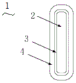
Description of reference numerals:
1. an insulated wire; 2. a conductor layer; 3. a semiconductive shield layer; 4. an insulating layer; 5. a high-voltage coil; 6. a segmentation unit; 9. a high voltage winding coil; 10. a base coil; 11. an airway; 12. a base terminal; 13. a tapping terminal; 14. an insulating pull rod; 15. an insulating rod; 16. clamping the structural member; 17. a high voltage winding; 18. an umbrella skirt; 19. an insulating cylinder; 20. a terminal boss; 21. a main insulating layer.
Detailed Description
The technical solutions of the present invention will be described clearly and completely with reference to the accompanying drawings, and it should be understood that the described embodiments are some, but not all embodiments of the present invention. All other embodiments, which can be derived by a person skilled in the art from the embodiments given herein without making any creative effort, shall fall within the protection scope of the present invention.
In the description of the present invention, it should be noted that the terms "center", "upper", "lower", "left", "right", "vertical", "horizontal", "inner", "outer", and the like indicate orientations or positional relationships based on the orientations or positional relationships shown in the drawings, and are only for convenience of description and simplicity of description, but do not indicate or imply that the device or element being referred to must have a specific orientation, be constructed and operated in a specific orientation, and thus, should not be construed as limiting the present invention. Furthermore, the terms "first," "second," and "third" are used for descriptive purposes only and are not to be construed as indicating or implying relative importance.
In the description of the present invention, it should be noted that, unless otherwise explicitly specified or limited, the terms "mounted," "connected," and "connected" are to be construed broadly, e.g., as meaning either a fixed connection, a removable connection, or an integral connection; can be mechanically or electrically connected; they may be connected directly or indirectly through intervening media, or they may be interconnected between two elements. The specific meanings of the above terms in the present invention can be understood in specific cases to those skilled in the art.
In addition, the technical features involved in the different embodiments of the present invention described below may be combined with each other as long as they do not conflict with each other.
Referring to fig. 1 to 8, the high-voltage winding structure of the dry-type insulated high-voltage transformer provided in this embodiment includes:
an insulating cylinder 19;
the high-voltage winding coil 9 is suitable for surrounding and being fixed on the insulating cylinder 19, the high-voltage winding coil 9 comprises an insulated wire 1, and the insulated wire 1 is formed by integrally forming a conductor layer 2 and a wrapping layer wrapping the outer side of the conductor layer 2;
and the main insulating layer 21 is suitable for wrapping the high-voltage winding coil 9, and the material of the main insulating layer 21 is the same as that of the outermost layer of the wrapping layer of the insulated wire 1.
Preferably, the molding mode of the main insulation layer 21 is casting molding, the main insulation layer 21 entirely wraps and fixes the high-voltage winding coil 9 on the insulation cylinder 19, and the material of the main insulation layer 21 is the same as that of the insulation layer 4 on the outermost layer of the insulated wire 1, so that the main insulation layer 21 and the insulation layer 4 are integrated into a whole, and thus the interface defect is effectively avoided.
The dry-type insulation high-voltage transformer high-voltage winding structure that this embodiment provided, through the material that sets up main insulation layer 21 with the outmost material on insulated wire 1's parcel layer is the same, has realized that the main insulation layer 21 of high-voltage winding coil 9 is fully compatible between with insulated wire 1, has effectively eliminated main insulation layer 21 with interface defects such as crackle, bubble between the insulated wire 1, simultaneously, because the uniformity of homogeneous material expend with heat and contract with cold under high and low temperature, effectively avoided main insulation layer 21 with the layering of micro interface between the insulated wire 1 to effectively avoid the partial discharge under the high pressure, promoted insulation reliability, be favorable to promoting high-voltage transformer's voltage class and capacity.
Specifically, the covering of the insulated wire 1 includes an insulating layer 4.
Specifically, as a modification, the covering of the insulated wire 1 includes a semiconductive shield layer 3 and an insulating layer 4.
As shown in fig. 1, the conductor layer 2 of the insulated wire 1 has a rectangular cross-sectional shape in the radial direction, and the wrapping layer includes a semiconductive shield layer 3 and an insulating layer 4; as shown in fig. 2, the wrapping layer comprises only the insulating layer 4.
The two types of wrapping layers are suitable for transformers with different voltage grades, when the voltage grade is higher, the insulated conducting wire 1 comprising the semi-conductive shielding layer 3 and the insulating layer 4 is used, the base materials of the semi-conductive shielding layer 3 and the insulating layer 4 are the same, but the resistivity of the semi-conductive shielding layer 3 is different from that of the insulating layer 4, the resistivity of the semi-conductive shielding layer 3 is very low, the thickness of the semi-conductive shielding layer is thinner, and the semi-conductive shielding layer 3 is equipotential with the shielded conductor layer 2, the electric field distribution is improved by arranging the semi-conductive shielding layer 3, and partial discharge of the conductor and the insulation caused by the unsmooth surface of the conductor layer 2 or the air gap between the conductor layer 2 and the wrapping layer is avoided; when the voltage level is low and the electric field is not high, partial discharge is not easy to occur, and the insulated wire 1 comprising the insulating layer 4 can be used.
When the wrapping layer only comprises the insulating layer 4, the conductor layer 2 and the insulating layer 4 of the insulated wire 1 are of an integrally formed structure; when the wrapping layer includes during semiconductive shield layer 3 and insulating layer 4, conductor layer 2 with semiconductive shield layer 3, insulating layer 4 are multilayer crowded integrated into one piece structure altogether, integrated into one piece structural style has effectively solved the layering interface problem between traditional dry-type insulation transformer's high-voltage winding wire and the epoxy insulating layer to reduce interface defect and partial discharge better.
As a modification, as shown in fig. 3 and 4, the conductor layer 2 has a circular cross-sectional shape in the radial direction.
The dry-type insulation high-voltage transformer high-voltage winding structure provided by the embodiment effectively eliminates the problem of interface layering between the conductor layer 2 and the wrapping layer by integrating the conductor layer 2 with the wrapping layer, so that the interface defect and the partial discharge can be better reduced, and the insulation strength and the electric strength of the high-voltage winding coil 9 are improved, so that compared with the traditional insulation paper or film wrapping molding, the voltage grade and the capacity of the high-voltage transformer are more favorably improved.
Specifically, the high-voltage winding coil 9 includes: the coil comprises a basic coil 10 and a plurality of coils, wherein the basic coil 10 is formed by winding an insulated conducting wire 1, and the basic coil 10 is provided with 1 layer or a plurality of layers;
and the air passages 11 are formed by gaps between two adjacent layers of the basic coils 10.
Preferably, when the base coil 10 is provided in multiple layers, the air duct 11 is provided between each adjacent two layers, and is adapted to dissipate heat during operation.
As a modification, an air passage is provided after n layers of the base coil 10 are continued, where n is 2 or more.
As a modification, in the case where the capacity and temperature rise are not high, the high-voltage winding coil 9 is not provided with the air passage 11.
The high-voltage winding structure of the dry-type insulation high-voltage transformer provided by the embodiment is characterized in that the basic coils 10 are arranged in 1 layer or multiple layers, and the air passages 11 are arranged between the adjacent two layers of the basic coils 10, so that the heat dissipation of the transformer in the working process is facilitated, the transformer is protected, and the service life is prolonged.
Specifically, the high-voltage winding structure of the dry-type insulated high-voltage transformer further comprises: an insulated pull rod 14, the insulated pull rod 14 comprising: the insulating rods 15 are long-strip-shaped, threads are arranged at two ends of each insulating rod 15, the number of the insulating rods 15 is two, and the two insulating rods 15 penetrate through the two adjacent air passages 11 along the axial direction of the basic coil 10 respectively; and
the number of the clamping structural members 16 is two, the two clamping structural members 16 are respectively in threaded connection with two ends of the insulating rod 15, each clamping structural member 16 is simultaneously connected with the two insulating rods 15, and the two clamping structural members 16 are suitable for exerting pre-tightening force on the base coil 10 along the axial direction of the base coil 10.
According to the high-voltage winding structure of the dry-type insulated high-voltage transformer, the insulating rods 15 provided with the insulating pull rods 14 penetrate through the two adjacent air passages 11, and the clamping structural members 16 of the insulating pull rods 14 apply pre-tightening force to the base coil 10 along the axial direction of the base coil 10, so that the base coil 10 is fastened, and the whole structure is neat and compact.
Specifically, the base coil 10 includes 1 or more units, each layer of the base coil 10 includes 1 or more turns of the insulated conductive wire 1, the base coil 10 is configured in a cylindrical shape, and the base coil 10 is formed of one segment unit 6 or is formed by laminating at least two segment units 6 in an axial direction of the base coil 10.
Specifically, when the base coil 10 is formed of one of the segment units 6, the base coil 10 includes: the number of the basic terminals 12 is 2, and 2 of the basic terminals 12 are respectively formed by two outlet ends of the segmentation unit 6 and are suitable for electrical connection among different high-voltage windings 17.
Specifically, when the base coil 10 is formed of at least two of the segment units 6, the base coil 10 includes:
the number of the basic terminals 12 is 2, and 2 basic terminals 12 are respectively formed by the wire outlet ends of the starting ends of the segmentation units 6 at two ends;
the number of the tapping terminals 13 is 2 or more, and the tapping terminals are formed by the wire outlet ends at the tail ends of the segmenting units 6 at the two ends, or formed by the wire outlet ends at the starting end and the wire outlet ends at the tail end of the segmenting unit 6 at the middle part.
Note that, the two ends refer to two ends of the base coil 10 in the axial direction; the outlet ends refer to two ends of the insulated wire 1 wound around the segmentation unit 6; the starting ends of the segment units 6 at both ends refer to the ends of the insulated conductive wire 1 close to the ends of the base coil 10 in the axial direction, and the ending ends of the segment units 6 at both ends refer to the ends of the insulated conductive wire 1 far from the ends of the base coil 10 in the axial direction; the start and end of the segment unit 6 located at the middle are referred to as both ends of the insulated conductive wire 1 around which the segment unit 6 is wound, respectively.
As shown in fig. 5, the base coil 10 includes a plurality of the segment units 6, each segment unit 6 includes 1 to n layers, each layer includes 1 to n turns of the insulated conductive wire 1, where n is a positive integer. When the segment unit 6 is located at both ends of the basic coil 10, the start end of the segment unit 6, i.e., the outlet terminal near the end of the basic coil 10, is formed as a basic terminal 12, and the outlet terminal at the end of the segment unit 6 is formed as a tapping terminal 13; when the segment unit 6 is located in the middle of the base coil 10, the outlet terminals of the start and end of the segment unit 6 are formed as tap terminals 13.
Preferably, the number of the tapping terminals 13 is multiple, and in the using process, different tapping terminals 13 are selected to be connected into a line, so that the number of turns of a coil in the line is adjusted, and different voltages and capacities are achieved.
The high-voltage winding structure of the dry-type insulated high-voltage transformer provided by the embodiment is formed by laminating the segmentation units 6 by arranging the base coil 10, can meet different voltage requirements by freely selecting the number of the segmentation units 6 connected to a line, and has better flexibility.
Preferably, the high voltage winding 17 further comprises: and a terminal boss 20 disposed to protrude from the main insulating layer 21 in a protruding structure and wrapping portions of the main terminal 12 and the tap terminal 13 close to the main insulating layer 21, and adapted to fix the main terminal 12 and the tap terminal 13, thereby ensuring terminal reliability when electrical connection is performed.
Specifically, the high-voltage winding structure of the dry-type insulated high-voltage transformer further comprises: and umbrella skirts 18 disposed at both ends of the high-voltage winding 17 in the axial direction, wherein the umbrella skirts 18 are configured as protrusions protruding from the main insulation layer 21 in the radial direction.
Preferably, the umbrella skirt 18 is constructed in an umbrella structure, and is disposed outside both ends of the high-voltage winding 17 in the axial direction, so as to increase the creepage distance along the plane.
The creepage distance refers to the shortest path between two conductive parts or between a conductive part and an equipment protection interface measured along an insulating surface, that is, under different use conditions, the insulating material around the conductor is electrically polarized, so that the insulating material is electrified. Due to the fact that the creepage distance along the surface is increased due to the umbrella-shaped structure of the umbrella skirt portion 18 protruding outwards, the insulating effect can be better achieved, the insulating strength of the surface is improved, the requirement of reliable surface insulation isolation of the high-voltage winding 17 on the ground in long-term operation is met, and safety is high.
According to the high-voltage winding structure of the dry-type insulation high-voltage transformer, the umbrella skirt portions 18 are arranged at the two ends of the high-voltage winding 17, so that the creepage distance along the surface is effectively increased, the insulation strength is improved, and the safety is improved.
Specifically, the material of the main insulating layer 21 is rubber;
the insulating layer 4 is made of rubber.
In the high-voltage winding structure of the dry-type insulated high-voltage transformer provided by the embodiment, the main insulating layer 21 and the insulating layer 4 of the insulated wire 1 are made of rubber, and the rubber has good elasticity, high formability, interface characteristics, heat dissipation characteristics and high insulating strength and can be recycled repeatedly, so that compared with a traditional transformer made of epoxy resin, the high-voltage winding structure of the dry-type insulated high-voltage transformer provided by the invention has better insulating characteristics and forming characteristics and is more environment-friendly.
It should be understood that the above examples are only for clarity of illustration and are not intended to limit the embodiments. Other variations and modifications will be apparent to persons skilled in the art in light of the above description. And are neither required nor exhaustive of all embodiments. And obvious variations or modifications therefrom are within the scope of the invention.
Claims (10)
1. A high-voltage winding structure of a dry-type insulated high-voltage transformer, comprising:
an insulating cylinder (19);
the high-voltage winding coil (9) is suitable for being wound around and fixed on the insulating cylinder (19), the high-voltage winding coil (9) comprises an insulated wire (1), and the insulated wire (1) is formed by integrally molding a conductor layer (2) and a wrapping layer wrapping the outer side of the conductor layer (2);
the main insulating layer (21) is suitable for wrapping the high-voltage winding coil (9), and the material of the main insulating layer (21) is the same as that of the outermost layer of the wrapping layer of the insulated wire (1).
2. A high voltage winding structure of a dry-type insulated high voltage transformer according to claim 1, characterized in that the outer covering of the insulated conductor (1) comprises an insulating layer (4).
3. A high voltage winding arrangement of a dry-type insulated high voltage transformer according to claim 1, characterized in that the wrapping of the insulated conductor (1) comprises a semiconducting shield layer (3) and an insulating layer (4).
4. A high-voltage winding structure of a dry-type insulated high-voltage transformer according to claim 1, characterized in that the high-voltage winding coil (9) comprises: the coil comprises a basic coil (10) and a plurality of coils, wherein the basic coil (10) is formed by winding an insulated wire (1), and the basic coil (10) is provided with 1 layer or a plurality of layers;
the air channel (11), the air channel (11) is formed by the gap between two adjacent layers of the basic coil (10).
5. A high-voltage winding structure of a dry-type insulated high-voltage transformer according to claim 4, further comprising: an insulated tie rod (14), the insulated tie rod (14) comprising: the insulating rods (15) are long-strip-shaped, threads are arranged at two ends of each insulating rod, the number of the insulating rods (15) is two, and the two insulating rods (15) penetrate through the two adjacent air passages (11) along the axial direction of the basic coil (10) respectively; and
the number of the clamping structural components (16) is two, the two clamping structural components (16) are respectively in threaded connection with two ends of the insulating rod (15), each clamping structural component (16) is simultaneously connected with the two insulating rods (15), and the two clamping structural components (16) are suitable for exerting pre-tightening force on the basic coil (10) along the axial direction of the basic coil (10).
6. A high voltage winding structure of a dry-type insulated high voltage transformer according to claim 4, wherein the base coil (10) comprises 1 or more units, each layer of the base coil (10) comprises 1 or more turns of the insulated conductive wire (1), the base coil (10) is configured in a cylindrical shape, and the base coil (10) is formed of one segmented unit (6) or is laminated with at least two segmented units (6) along an axial direction of the base coil (10).
7. A dry-type insulated high voltage transformer high voltage winding structure according to claim 6, characterized in that when the base coil (10) is formed of one of the segment units (6), the base coil (10) comprises: the number of the basic terminals (12) is 2, and 2 basic terminals (12) are respectively formed by two outlet ends of the segmenting unit (6) and are suitable for electrical connection among different high-voltage windings (17).
8. A dry-type insulated high voltage transformer high voltage winding structure according to claim 6, characterized in that when the base coil (10) is formed of at least two of said segment units (6), the base coil (10) comprises:
the number of the basic terminals (12) is 2, and the 2 basic terminals (12) are respectively formed by the wire outlet ends of the starting ends of the segmentation units (6) at two ends;
the number of the tapping terminals (13) is 2 or more, and the tapping terminals are formed by the wire outlet ends at the tail ends of the segmenting units (6) positioned at the two ends, or the wire outlet ends at the starting end and the wire outlet ends at the tail ends of the segmenting units (6) positioned in the middle.
9. A high voltage winding structure of a dry-type insulated high voltage transformer according to claim 7, further comprising: and umbrella skirt portions (18) arranged at two ends of the high-voltage winding (17) along the axial direction, wherein the umbrella skirt portions (18) are constructed into a protruding structure protruding from the main insulating layer (21) along the radial direction.
10. A high-voltage winding structure of a dry-type insulated high-voltage transformer according to any one of claims 1-9, characterized in that the material of the primary insulating layer (21) is rubber;
the insulating layer (4) is made of rubber.
Priority Applications (1)
| Application Number | Priority Date | Filing Date | Title |
|---|---|---|---|
| CN202110875427.6A CN113451017A (en) | 2021-07-30 | 2021-07-30 | High-voltage winding structure of dry-type insulation high-voltage transformer |
Applications Claiming Priority (1)
| Application Number | Priority Date | Filing Date | Title |
|---|---|---|---|
| CN202110875427.6A CN113451017A (en) | 2021-07-30 | 2021-07-30 | High-voltage winding structure of dry-type insulation high-voltage transformer |
Publications (1)
| Publication Number | Publication Date |
|---|---|
| CN113451017A true CN113451017A (en) | 2021-09-28 |
Family
ID=77817857
Family Applications (1)
| Application Number | Title | Priority Date | Filing Date |
|---|---|---|---|
| CN202110875427.6A Pending CN113451017A (en) | 2021-07-30 | 2021-07-30 | High-voltage winding structure of dry-type insulation high-voltage transformer |
Country Status (1)
| Country | Link |
|---|---|
| CN (1) | CN113451017A (en) |
Cited By (1)
| Publication number | Priority date | Publication date | Assignee | Title |
|---|---|---|---|---|
| CN114300235A (en) * | 2021-12-29 | 2022-04-08 | 江苏神马电力股份有限公司 | High-voltage winding and dry-type transformer |
-
2021
- 2021-07-30 CN CN202110875427.6A patent/CN113451017A/en active Pending
Cited By (1)
| Publication number | Priority date | Publication date | Assignee | Title |
|---|---|---|---|---|
| CN114300235A (en) * | 2021-12-29 | 2022-04-08 | 江苏神马电力股份有限公司 | High-voltage winding and dry-type transformer |
Similar Documents
| Publication | Publication Date | Title |
|---|---|---|
| CN110323043B (en) | Seriation semi-filling and sealing through type high-voltage high-frequency transformer structure | |
| EP2992538B1 (en) | Hv instrument transformer | |
| JP4794999B2 (en) | Lightning proof type low voltage insulation transformer | |
| JP2000173836A (en) | Electrostatic induction equipment | |
| CN108305764A (en) | A kind of dry type high frequency transformer | |
| CN113451017A (en) | High-voltage winding structure of dry-type insulation high-voltage transformer | |
| CN215496326U (en) | High-voltage winding structure of dry-type insulation high-voltage transformer | |
| CN208256440U (en) | A kind of dry type high frequency transformer | |
| CN201449851U (en) | Tinsel cord mixed-winding coil grounding transformer | |
| CN116313439B (en) | Insulation pouring structure and pouring manufacturing method for high-voltage coil of transformer | |
| JP6255697B2 (en) | Resin molded coil, manufacturing method thereof, and molded transformer | |
| CN215417829U (en) | Dry-type insulation high-voltage transformer | |
| JP7224798B2 (en) | Method for manufacturing mold-type electrical equipment | |
| CN216119863U (en) | High-voltage winding of dry type transformer | |
| CN113488321B (en) | Dry-type transformer and winding method thereof | |
| CN217468167U (en) | Axial segmentation multi-winding dry-type transformer | |
| JP2855862B2 (en) | Resin mold current transformer | |
| CN212230218U (en) | Dry-type transformer | |
| JP5663322B2 (en) | Resin molded coil and molded transformer using the same | |
| CN113451021A (en) | Dry-type insulation high-voltage transformer | |
| US20230154672A1 (en) | Transformer and power equipment | |
| KR102075878B1 (en) | High Voltage Windings and High Voltage Electromagnetic Induction Devices | |
| JP2024506149A (en) | Winding bodies, high voltage windings and dry type transformers | |
| CN115732202A (en) | High-voltage winding based on silicon rubber insulation and transformer | |
| CN113823489A (en) | High-voltage winding of dry type transformer |
Legal Events
| Date | Code | Title | Description |
|---|---|---|---|
| PB01 | Publication | ||
| PB01 | Publication | ||
| SE01 | Entry into force of request for substantive examination | ||
| SE01 | Entry into force of request for substantive examination |