CN113445759A - A assembled platform of unloading safely for construction - Google Patents
A assembled platform of unloading safely for construction Download PDFInfo
- Publication number
- CN113445759A CN113445759A CN202110614227.5A CN202110614227A CN113445759A CN 113445759 A CN113445759 A CN 113445759A CN 202110614227 A CN202110614227 A CN 202110614227A CN 113445759 A CN113445759 A CN 113445759A
- Authority
- CN
- China
- Prior art keywords
- plate
- platform
- installation
- sliding
- positioning
- Prior art date
- Legal status (The legal status is an assumption and is not a legal conclusion. Google has not performed a legal analysis and makes no representation as to the accuracy of the status listed.)
- Withdrawn
Links
Images


Classifications
-
- E—FIXED CONSTRUCTIONS
- E04—BUILDING
- E04G—SCAFFOLDING; FORMS; SHUTTERING; BUILDING IMPLEMENTS OR AIDS, OR THEIR USE; HANDLING BUILDING MATERIALS ON THE SITE; REPAIRING, BREAKING-UP OR OTHER WORK ON EXISTING BUILDINGS
- E04G21/00—Preparing, conveying, or working-up building materials or building elements in situ; Other devices or measures for constructional work
- E04G21/14—Conveying or assembling building elements
- E04G21/16—Tools or apparatus
- E04G21/166—Landings, receiving platforms
Abstract
The invention discloses an assembled safe unloading platform for building construction, which comprises a platform bracket, wherein the platform bracket is used for positioning and installing an integral platform; the discharging platform device is used for stacking and transferring building materials; the discharging platform device comprises a connecting base, a material loading sliding plate is slidably mounted on the upper surface of the connecting base, reinforcing connecting plates are arranged on two sides of the material loading sliding plate, one side of each reinforcing connecting plate is fixedly connected with a protection connecting plate, and one end of the upper surface of the connecting base is provided with a protection connecting table. The invention has the beneficial effects that: the invention utilizes the positioning connecting plate to strengthen the connection between the two supporting connecting beams, improves the stability of the supporting connecting beams, improves the installation stability of the platform bracket through the installation connecting arm, improves the connection stability between the platform bracket and the building pillar, and reduces the installation difficulty of the bracket.
Description
Technical Field
The invention relates to an assembled safe discharging platform, in particular to an assembled safe discharging platform for building construction, and belongs to the technical field of building construction.
Background
The unloading platform is a framework type platform which is usually used for bearing materials in a certain construction period and carrying out various operations therein and is called as an operation platform. The operation platform is divided into a mobile operation platform, a floor type operation platform and an overhanging type operation platform, and can also be called as a material transferring platform.
In the using process of the existing operating platform, various materials are often required to be unloaded and then transferred, so that a protection facility is required to be installed at the side of the unloading platform for protection, but the existing protection facility is too simple and is generally directly installed on the unloading platform, the connection mode is simple, the rigidity is not enough, and the damage is easy to occur; the existing discharging platform is generally a whole, is directly fixedly connected with a building wall body, is not only inconvenient to install, but also is inconvenient to transfer materials when in use.
Disclosure of Invention
The invention aims to solve the problems and provide a fabricated safe discharging platform for building construction.
The invention achieves the above-mentioned purpose through the following technical scheme, the assembled safe unloading platform for building construction comprises:
the platform bracket is used for positioning and mounting the integral platform;
the discharging platform device is used for stacking and transferring building materials;
the discharging platform device comprises a connecting base, a material-carrying sliding plate is slidably mounted on the upper surface of the connecting base, reinforcing connecting plates are arranged on two sides of the material-carrying sliding plate, a protective connecting plate is fixedly connected to one side of each reinforcing connecting plate, a protective connecting table is arranged at one end of the upper surface of the connecting base, a connecting table fixing rod is clamped at the bottom end of each protective connecting table, and two sliding connecting seats are fixedly mounted at the bottom end of the connecting base;
the upper surface of the connecting base is provided with two limiting installation grooves, one side groove wall of each limiting installation groove is provided with three connecting installation grooves, limiting reinforcing bodies are fixedly installed inside the connecting installation grooves, and the upper surface of the connecting base is provided with a lower fixing rod installation groove;
three first positioning threaded holes are formed in one side face of the protection connecting plate at equal intervals, three groups of second mounting threaded holes are formed in the bottom of the protection connecting plate at equal intervals, and three connector slots are formed in the bottom of the protection connecting plate at equal intervals;
the protection connecting platform comprises a supporting connecting seat, wherein the two sides of the supporting connecting seat are fixedly connected with connecting side plates, three second positioning threaded holes are formed in the same side of each connecting side plate in an equal distance mode, a rotating protection plate is installed on one side of each connecting side plate in a rotating mode, and an upper fixing rod mounting groove is formed in the bottom end of the supporting connecting seat.
Preferably, the platform support includes that two support tie-beams, two fixed mounting has the connection crossbeam between the support tie-beam, support tie-beam bottom integrated into one piece has the spacing connector, spacing connector one side fixedly connected with supports the down tube, the one end fixedly connected with location connecting plate of supporting the down tube, the one side fixedly connected with installation linking arm of support tie-beam, support the tie-beam top and seted up the sliding installation groove, location connecting plate top fixedly connected with two fixed connection scutches.
Preferably, two sets of connecting threaded holes are formed in the upper surface of the connecting base, each set of connecting threaded holes comprises three connecting threaded holes which are formed at equal intervals, three sets of fixing threaded holes are formed in the two side equal intervals of the upper surface of the connecting base, and each set of fixing threaded holes comprises two fixing threaded holes.
Preferably, the limiting reinforcing body comprises a horizontal fixing plate and a vertical inserting plate, two threaded holes are formed in the top end of the horizontal fixing plate, and the vertical inserting plate is inserted into the connecting and mounting groove.
Preferably, the upper surface of the connecting base is integrally formed with two triangular slide rails, the upper surface of the connecting base is provided with triangular slide grooves, the lower surface of the material loading sliding plate is provided with two corresponding slide grooves, and the lower surface of the material loading sliding plate is integrally formed with corresponding slide rails.
Preferably, three bolt positioning grooves are formed in the top of one side of the reinforcing connecting plate at equal intervals, and two first installation threaded holes are formed in the bolt positioning grooves.
Preferably, the bottom end of the protective connecting plate is integrally formed with a limiting installation body, and the limiting installation body is slidably installed inside the sliding installation groove.
Preferably, the connecting table fixing rod comprises a positioning connecting rod, one end of the positioning connecting rod is fixedly provided with a limiting connector, and the other end of the positioning connecting rod is integrally formed with a fixed connector.
Preferably, the sliding connection seat comprises a sliding installation shell, an installation positioning threaded hole is formed in one end of the upper surface of the sliding installation shell, five limiting threaded holes are formed in the upper surface of the sliding installation shell at equal intervals, and the bottom end of the sliding installation shell is rotatably provided with a rotating roller.
Preferably, the top of the connecting table fixing rod is clamped in the upper fixing rod mounting groove, and the bottom of the connecting table fixing rod is clamped in the lower fixing rod mounting groove.
The invention has the beneficial effects that:
the positioning connecting plate is used for reinforcing connection between the two supporting connecting beams, the stability of the supporting connecting beams is improved, meanwhile, the installation stability of the platform support is improved through the installation connecting arm, the connection stability between the platform support and a building pillar is improved, the installation difficulty of the support is reduced, the positioning connecting plate is attached to a building crossbeam, the supporting of the supporting connecting beams on the discharging platform device is further enhanced through the supporting oblique rods, and the carrying quality of the whole discharging platform device is improved.
The connecting platform fixing rod is used for simplifying the connection between the protective connecting platform and the connecting base, the protective connecting platform is connected with the protective connecting plate through the bolt, the mounting stability of the protective connecting plate is enhanced, the mounting stability between the protective connecting plate and the connecting base is improved through the limiting reinforcing body, the mounting steps are simplified, the stability of the protective connecting plate is improved, and meanwhile the protective capacity of the protective connecting plate is improved through the reinforcing connecting plate.
Thirdly, the material loading sliding plate is used for unloading and transferring materials, so that the materials can be transferred conveniently, the material transferring efficiency is directly improved, the rotating difficulty of the whole materials is reduced, the use of the whole device is facilitated, the assembling difficulty of the whole device is reduced, and the whole using difficulty is also reduced.
Drawings
FIG. 1 is a schematic view of the overall structure of the present invention;
FIG. 2 is a schematic view of a platform support structure according to the present invention;
FIG. 3 is a schematic structural view of a discharge platform apparatus according to the present invention;
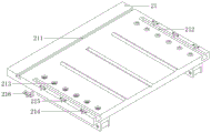
FIG. 4 is a schematic view of the connecting base structure of the present invention;
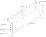
FIG. 5 is a schematic view of the construction of the reinforcing connecting plate and the protective connecting plate according to the present invention;
FIG. 6 is a schematic view of a protective docking station according to the present invention;
FIG. 7 is a schematic view of a fixing rod structure of the connecting platform of the present invention;
fig. 8 is a schematic view of the sliding connection seat of the present invention.
In the figure: 1. a platform support; 11. supporting the connecting beam; 12. connecting the cross beam; 13. a limiting connector; 14. supporting the diagonal rods; 15. positioning the connecting plate; 16. mounting a connecting arm; 17. a sliding mounting groove; 18. fixedly connecting angle plates; 2. a discharge platform device; 21. connecting a base; 211. a lower fixing rod mounting groove; 212. a limiting mounting groove; 213. connecting the threaded hole; 214. connecting the mounting groove; 215. fixing the threaded hole; 216. a limiting reinforcing body; 22. a material-carrying sliding plate; 23. reinforcing the connecting plate; 231. positioning a bolt groove; 232. a first mounting threaded hole; 24. a protective connecting plate; 241. a first positioning threaded hole; 242. a second mounting threaded hole; 243. a connector slot; 244. a limiting installation body; 25. a protective connecting table; 251. supporting the connecting seat; 252. connecting the side plates; 253. a second positioning threaded hole; 254. an upper fixing rod mounting groove; 255. rotating the protection plate; 26. a connecting table fixing rod; 261. positioning the connecting rod; 262. a limiting connector; 27. a sliding connection seat; 271. a sliding mounting housing; 272. installing a positioning threaded hole; 273. a limiting threaded hole; 274. the roller is rotated.
Detailed Description
The technical solutions in the embodiments of the present invention will be clearly and completely described below with reference to the drawings in the embodiments of the present invention, and it is obvious that the described embodiments are only a part of the embodiments of the present invention, and not all of the embodiments. All other embodiments, which can be derived by a person skilled in the art from the embodiments given herein without making any creative effort, shall fall within the protection scope of the present invention.
Referring to fig. 1 to 8, an assembled safety discharging platform for building construction includes:
the platform support 1 is used for positioning and mounting the integral platform;
as a technical optimization scheme of the invention, the platform bracket 1 comprises two supporting connecting beams 11, a connecting beam 12 is fixedly arranged between the two supporting connecting beams 11, two ends of the connecting beam 12 are respectively clamped inside clamping grooves formed in the two supporting connecting beams 11, the supporting connecting beams 11 are fixedly connected with the connecting beam 12 through two bolts, a limiting connecting body 13 is integrally formed at the bottom end of each supporting connecting beam 11, a supporting inclined rod 14 is fixedly connected to one side of each limiting connecting body 13, one end of each supporting inclined rod 14 is clamped inside the corresponding limiting connecting body 13 through a clamping block, a bolt is arranged on one side of each limiting connecting body 13 in a threaded manner, the limiting connecting body 13 is fixedly connected with the supporting inclined rod 14 through a bolt, one end of each supporting inclined rod 14 is fixedly connected with a positioning connecting plate 15, two clamping blocks are integrally formed at the other end of each supporting inclined rod 14, and the supporting inclined rod 14 is fixedly connected with the positioning connecting plates 15 through bolts, positioning connection board 15 sets up in two 11 bottoms of support tie-beam, one side fixedly connected with erection joint arm 16 of support tie-beam 11, erection joint arm 16 with support tie-beam 11 casting shaping as an organic whole, three screw hole has been seted up to 16 top equidistance of erection joint arm, sliding mounting groove 17 has been seted up on support tie-beam 11 top, sliding connection seat 27 slidable mounting is inside sliding mounting groove 17, two fixed connection scute 18 of positioning connection board 15 top fixedly connected with, fixed connection scute 18 sets up to the board of buckling at right angle, bolt and 15 fixed connection of positioning connection board are passed through to one end, the other end passes through the bolt and supports 11 fixed connection of tie-beam.
The discharging platform device 2 is used for stacking and transferring building materials;
as a technical optimization scheme of the invention, the discharging platform device 2 comprises a connecting base 21, a material loading sliding plate 22 is slidably mounted on the upper surface of the connecting base 21, reinforcing connecting plates 23 are arranged on two sides of the material loading sliding plate 22, a protective connecting plate 24 is fixedly connected to one side of each reinforcing connecting plate 23, a protective connecting table 25 is arranged at one end of the upper surface of the connecting base 21, a connecting table fixing rod 26 is clamped at the bottom end of each protective connecting table 25, and two sliding connecting seats 27 are fixedly mounted at the bottom end of the connecting base 21;
as a technical optimization scheme of the present invention, two limit installation grooves 212 are formed on the upper surface of the connection base 21, the limit installation grooves 212 are formed on both sides of the upper surface of the connection base 21, three connection installation grooves 214 are formed on one side wall of the limit installation groove 212, the three connection installation grooves 214 are equidistantly formed, a limit reinforcement body 216 is fixedly installed inside the connection installation groove 214, and a lower fixing rod installation groove 211 is formed on the upper surface of the connection base 21; the upper surface of the connecting base 21 is provided with two groups of connecting threaded holes 213, each group of connecting threaded holes 213 comprises three connecting threaded holes 213 which are arranged at equal intervals, two sides of the upper surface of the connecting base 21 are provided with three groups of fixing threaded holes 215 at equal intervals, each group of fixing threaded holes 215 comprises two fixing threaded holes 215, and the two fixing threaded holes 215 are arranged at two sides of one connecting installation groove 214; the limiting reinforcing body 216 comprises a horizontal fixing plate and a vertical inserting plate, the horizontal fixing plate and the vertical inserting plate are integrally cast and formed, the vertical inserting plate is inserted into the connector slot 243, two threaded holes are formed in the top end of the horizontal fixing plate, and the vertical inserting plate is inserted into the connector mounting groove 214.
As a technical optimization scheme of the invention, two triangular slide rails are integrally formed on the upper surface of the connecting base 21, triangular slide grooves are formed on the upper surface of the connecting base 21, two corresponding slide grooves are formed on the lower surface of the material-carrying slide plate 22, corresponding slide rails are integrally formed on the lower surface of the material-carrying slide plate 22, the two corresponding slide grooves are slidably clamped at the top ends of the two triangular slide rails, and the corresponding slide rails are slidably mounted in the triangular slide grooves.
As a technical optimization scheme of the invention, three bolt positioning grooves 231 are equidistantly formed in the top of one side of the reinforcing connecting plate 23, two first mounting threaded holes 232 are formed in the bolt positioning grooves 231, the first mounting threaded holes 232 penetrate through the reinforcing connecting plate 23, a vertical thirty-degree inclined surface is formed in the top of one side of the reinforcing connecting plate 23, and the bolt positioning grooves 231 are formed in the inclined surface.
As a technical optimization scheme of the invention, three first positioning threaded holes 241 are equidistantly formed in one side surface of the protective connecting plate 24, three groups of second mounting threaded holes 242 are equidistantly formed in the bottom of the protective connecting plate 24, each group of second mounting threaded holes 242 comprises two second mounting threaded holes 242, the six second mounting threaded holes 242 correspond to the six first mounting threaded holes 232, the reinforcing connecting plate 23 is fixedly connected with the protective connecting plate 24 through bolts, and three connecting body slots 243 are equidistantly formed in the bottom of the protective connecting plate 24; the bottom end of the protective connecting plate 24 is integrally formed with a limiting installation body 244, and the limiting installation body 244 is slidably installed inside the sliding installation groove 17.
As a technical optimization scheme of the invention, the protective connecting table 25 comprises a supporting connecting seat 251, the top of one side of the supporting connecting seat 251 is provided with a forty-five degree inclined surface, the bottom of the inclined surface of the supporting connecting seat 251 is in mutual contact with the material loading sliding plate 22, two sides of the supporting connecting seat 251 are both fixedly connected with connecting side plates 252, the connecting side plates 252 and the supporting connecting seat 251 are integrally cast and formed, one side of each connecting side plate 252 is equidistantly provided with three second positioning threaded holes 253, the second positioning threaded holes 253 correspond to the first positioning threaded holes 241, one side of each connecting side plate 252 is rotatably provided with a rotating protection plate 255, each connecting side plate 252 is rotatably connected with the corresponding rotating protection plate 255 through a rotating shaft sleeve, the two rotating protection plates 255 are mutually clamped through fixing bolts, one end of the top end of the corresponding rotating protection plate 255, far away from the connecting side plate 252, is provided with an inserting pin hole, the rotating protection plate 255 is arranged at the top end of the supporting connecting seat 251, an upper fixing rod mounting groove 254 is formed at the bottom end of the supporting connection seat 251, and two ends of the upper fixing rod mounting groove 254 are connected with the side plate 252 in a penetrating manner.
As a technical optimization scheme of the invention, the connecting table fixing rod 26 comprises a positioning connecting rod 261, one end of the positioning connecting rod 261 is fixedly provided with a limit connector 262, the other end of the positioning connecting rod 261 is integrally formed with a fixed connector, one end of the positioning connecting rod 261 is provided with an insertion groove, one side of the limit connector 262 is integrally formed with an insertion block, the insertion block is inserted into the insertion groove, the limit connector 262 is fixedly connected with the positioning connecting rod 261 through a bolt, and the limit connector 262 and the fixed connector are arranged in an i shape with the same size; the top of the connecting table fixing rod 26 is clamped inside the upper fixing rod mounting groove 254, and the bottom of the connecting table fixing rod 26 is clamped inside the lower fixing rod mounting groove 211.
As a technical optimization scheme of the invention, the sliding connection seat 27 comprises a sliding installation shell 271, one end of the upper surface of the sliding installation shell 271 is provided with an installation positioning threaded hole 272, the installation positioning threaded hole 272 corresponds to one connection threaded hole 213, the upper surface of the sliding installation shell 271 is equidistantly provided with five limit threaded holes 273, the five limit threaded holes 273 correspond to the five connection threaded holes 213, the bottom end of the sliding installation shell 271 is rotatably provided with a rotating roller 274, the bottom end of the sliding installation shell 271 is provided with a roller installation groove, and the rotating roller 274 is rotatably installed in the roller installation groove.
When the invention is used;
please refer to fig. 1 to 8;
assembling operation I;
firstly, assembling a platform bracket 1;
the connecting beam 12 is arranged between the two supporting and connecting beams 11, the positioning connecting plate 15 is fixedly connected with the supporting and connecting beams 11 through the fixed connecting angle plate 18, and then the two ends of the supporting diagonal rod 14 are respectively assembled with the limiting connecting body 13 and the positioning connecting plate 15 through bolts;
then, the assembled platform support 1 is placed to a designated position, the two mounting connecting arms 16 are clamped with the floor supporting columns, then the mounting is carried out through bolts, and meanwhile, the positioning connecting plate 15 is attached to the outer wall of the floor connecting plate, so that the mounting stability of the platform support 1 is improved;
assembling operation II;
then assembling the discharging platform device 2;
firstly, fixedly installing two sliding connection seats 27 at the bottom end of the connection base 21 through bolts, and then slidably installing the sliding connection seats 27 in the sliding installation groove 17;
then, the assembled protective connecting table 25 is placed on the upper surface of the connecting base 21, so that the upper fixing rod mounting groove 254 corresponds to the lower fixing rod mounting groove 211, then the positioning connecting rod 261 is inserted into the upper fixing rod mounting groove 254 and the lower fixing rod mounting groove 211 through the fixed connector, so that the fixed connector is clamped with the protective connecting table 25 and the connecting base 21, then the limit connector 262 is clamped into the upper fixing rod mounting groove 254 and the lower fixing rod mounting groove 211, and the limit connector 262 is fixedly connected with the positioning connecting rod 261 through a bolt;
then, the two protection connecting plates 24 are slidably mounted inside the two limiting mounting grooves 212 through the limiting mounting bodies 244, then the limiting reinforcing bodies 216 are inserted inside the connecting mounting grooves 214, so that the vertical inserting plates of the limiting reinforcing bodies 216 are inserted inside the connecting body slots 243, then the horizontal fixing plate is fixedly mounted at the top end of the connecting base 21 through bolts, and meanwhile, the protection connecting plates 24 are fixedly connected with the connecting side plates 252 through the bolts, the first positioning threaded holes 241 and the second positioning threaded holes 253;
then, the reinforcing connecting plate 23 is fixedly connected with the protective connecting plate 24, the reinforcing connecting plate 23 is fixed with the protective connecting plate 24 through the bolts, the first mounting threaded holes 232 and the second mounting threaded holes 242, and the bottom end of the reinforcing connecting plate 23 is fixedly connected with the connecting base 21;
finally, the material loading sliding plate 22 is slidably arranged at the top end of the connecting base 21;
carrying out operation;
as shown in fig. 1, in an initial state of the device, the two rotating protection plates 255 are firstly opened outwards, then the material is moved to the top end of the material loading sliding plate 22 through a tower crane, and then the rotating protection plates 255 are closed;
the discharging platform device 2 is then moved to the top end of the platform support 1 through the sliding connection base 27, so that the discharging platform device 2 is moved to the top end of the indoor part of the platform support 1, and then the material loading sliding plate 22 and the material on the top end thereof are rotated together and transferred to the indoor part for discharging the material.
To those skilled in the art;
firstly, the invention utilizes the positioning connecting plate 15 to strengthen the connection between the two supporting connecting beams 11, improves the stability of the supporting connecting beams 11, simultaneously improves the installation stability of the platform support 1 through the installation connecting arm 16, improves the connection stability between the platform support 1 and the building pillar, reduces the installation difficulty of the support, fits between the positioning connecting plate 15 and the building beam, further strengthens the support of the supporting connecting beams 11 to the discharging platform device 2 through the supporting diagonal rods 14, and improves the carrying quality of the whole discharging platform device 2.
Secondly, the connection between the protective connecting platform 25 and the connecting base 21 is simplified by the connecting platform fixing rod 26, the protective connecting platform 25 and the protective connecting plate 24 are connected through bolts, the mounting stability of the protective connecting plate 24 is enhanced, the mounting stability between the protective connecting plate 24 and the connecting base 21 is improved through the limiting reinforcing body 216, the mounting steps are simplified, the stability of the protective connecting plate 24 is improved, and meanwhile the protection capability of the protective connecting plate 24 is improved through the reinforcing connecting plate 23.
Thirdly, the material loading sliding plate 22 is used for unloading and transferring materials, so that the materials can be transferred conveniently, the material transferring efficiency is directly improved, the rotating difficulty of the whole materials is reduced, the use of the whole device is facilitated, the assembling difficulty of the whole device is reduced, and the whole using difficulty is also reduced.
Furthermore, it should be understood that although the present description refers to embodiments, not every embodiment may contain only a single embodiment, and such description is for clarity only, and those skilled in the art should integrate the description, and the embodiments may be combined as appropriate to form other embodiments understood by those skilled in the art.
Claims (10)
1. A assembled safe platform of unloading for construction, its characterized in that includes:
the platform support (1), the said platform support (1) is used for positioning and installing the integral platform;
the discharging platform device (2), the discharging platform device (2) is used for stacking and transferring building materials;
the discharging platform device (2) comprises a connecting base (21), a material loading sliding plate (22) is slidably mounted on the upper surface of the connecting base (21), reinforcing connecting plates (23) are arranged on two sides of the material loading sliding plate (22), a protective connecting plate (24) is fixedly connected to one side of each reinforcing connecting plate (23), a protective connecting table (25) is arranged at one end of the upper surface of the connecting base (21), a connecting table fixing rod (26) is clamped at the bottom end of each protective connecting table (25), and two sliding connecting seats (27) are fixedly mounted at the bottom end of the connecting base (21);
the upper surface of the connecting base (21) is provided with two limiting installation grooves (212), the groove wall of one side of each limiting installation groove (212) is provided with three connecting installation grooves (214), a limiting reinforcing body (216) is fixedly installed inside each connecting installation groove (214), and the upper surface of the connecting base (21) is provided with a lower fixing rod installation groove (211);
three first positioning threaded holes (241) are formed in one side face of the protection connecting plate (24) at equal intervals, three groups of second mounting threaded holes (242) are formed in the bottom of the protection connecting plate (24) at equal intervals, and three connector slots (243) are formed in the bottom of the protection connecting plate (24) at equal intervals;
the protection connecting table (25) comprises a supporting connecting seat (251), wherein two sides of the supporting connecting seat (251) are fixedly connected with connecting side plates (252), three second positioning threaded holes (253) are formed in one side of each connecting side plate (252) in an equal distance mode, a rotating protection plate (255) is installed on one side of each connecting side plate (252) in a rotating mode, and an upper fixing rod installing groove (254) is formed in the bottom end of the supporting connecting seat (251).
2. The fabricated safe discharge platform for building construction according to claim 1, wherein: platform support (1) includes two support tie-beam (11), two support fixed mounting has between tie-beam (11) to connect crossbeam (12), support tie-beam (11) bottom integrated into one piece spacing connector (13), spacing connector (13) one side fixedly connected with supports down tube (14), support one end fixedly connected with positioning connection board (15) of down tube (14), support one side fixedly connected with installation linking arm (16) of tie-beam (11), support tie-beam (11) top and seted up sliding mounting groove (17), two fixed connection scute (18) of positioning connection board (15) top fixedly connected with.
3. The fabricated safe discharge platform for building construction according to claim 1, wherein: two sets of connecting screw hole (213) have been seted up to connecting base (21) upper surface, every group connecting screw hole (213) include connecting screw hole (213) that three equidistance was seted up, three fixed screw hole of group (215) have been seted up to the both sides equidistance of connecting base (21) upper surface, and every fixed screw hole of group (215) includes two fixed screw hole (215).
4. The fabricated safe discharge platform for building construction according to claim 1, wherein: the limiting reinforcing body (216) comprises a horizontal fixing plate and a vertical inserting plate, two threaded holes are formed in the top end of the horizontal fixing plate, and the vertical inserting plate is inserted into the connecting and mounting groove (214).
5. The fabricated safe discharge platform for building construction according to claim 1, wherein: the material loading device is characterized in that two triangular sliding rails are integrally formed on the upper surface of the connecting base (21), triangular sliding grooves are formed in the upper surface of the connecting base (21), two corresponding sliding grooves are formed in the lower surface of the material loading sliding plate (22), and corresponding sliding rails are integrally formed on the lower surface of the material loading sliding plate (22).
6. The fabricated safe discharge platform for building construction according to claim 1, wherein: three bolt positioning grooves (231) are formed in the top of one side of the reinforcing connecting plate (23) in an equidistant mode, and two first installation threaded holes (232) are formed in the bolt positioning grooves (231).
7. The fabricated safe discharge platform for building construction according to claim 1, wherein: the protection connecting plate (24) bottom integrated into one piece has spacing installation body (244), spacing installation body (244) slidable mounting is inside slide mounting groove (17).
8. The fabricated safe discharge platform for building construction according to claim 1, wherein: connect platform dead lever (26) including location connecting rod (261), location connecting rod (261) one end fixed mounting has spacing connector (262), location connecting rod (261) other end integrated into one piece has fixed connector.
9. The fabricated safe discharge platform for building construction according to claim 1, wherein: the sliding connection seat (27) comprises a sliding installation shell (271), an installation positioning threaded hole (272) is formed in one end of the upper surface of the sliding installation shell (271), five limiting threaded holes (273) are formed in the equal distance of the upper surface of the sliding installation shell (271), and a rotating roller (274) is rotatably installed at the bottom end of the sliding installation shell (271).
10. The fabricated safe discharge platform for building construction according to claim 1, wherein: the top of the connecting table fixing rod (26) is clamped in the upper fixing rod mounting groove (254), and the bottom of the connecting table fixing rod (26) is clamped in the lower fixing rod mounting groove (211).
Priority Applications (1)
| Application Number | Priority Date | Filing Date | Title |
|---|---|---|---|
| CN202110614227.5A CN113445759A (en) | 2021-06-02 | 2021-06-02 | A assembled platform of unloading safely for construction |
Applications Claiming Priority (1)
| Application Number | Priority Date | Filing Date | Title |
|---|---|---|---|
| CN202110614227.5A CN113445759A (en) | 2021-06-02 | 2021-06-02 | A assembled platform of unloading safely for construction |
Publications (1)
| Publication Number | Publication Date |
|---|---|
| CN113445759A true CN113445759A (en) | 2021-09-28 |
Family
ID=77810716
Family Applications (1)
| Application Number | Title | Priority Date | Filing Date |
|---|---|---|---|
| CN202110614227.5A Withdrawn CN113445759A (en) | 2021-06-02 | 2021-06-02 | A assembled platform of unloading safely for construction |
Country Status (1)
| Country | Link |
|---|---|
| CN (1) | CN113445759A (en) |
Cited By (1)
| Publication number | Priority date | Publication date | Assignee | Title |
|---|---|---|---|---|
| CN113898189A (en) * | 2021-11-19 | 2022-01-07 | 宋华金 | Assembled safe platform of unloading of construction |
Citations (14)
| Publication number | Priority date | Publication date | Assignee | Title |
|---|---|---|---|---|
| US20100119336A1 (en) * | 2007-05-29 | 2010-05-13 | Navarra Intelligent Concrete System S L | Automatic system for construction of buildings |
| JP2012167468A (en) * | 2011-02-14 | 2012-09-06 | Seiji Takechi | Unloading device |
| JP2014152467A (en) * | 2013-02-06 | 2014-08-25 | Shinwa Kk | Material carrier lift |
| US20150107186A1 (en) * | 2012-06-11 | 2015-04-23 | Thyssenkrupp Elevator Ag | Method and mounting system for mounting lift components |
| CN209637243U (en) * | 2019-01-18 | 2019-11-15 | 中建七局(上海)有限公司 | One kind being used for construction assembled discharging platform |
| CN111005578A (en) * | 2019-12-25 | 2020-04-14 | 朱蓓 | Construction is with platform of unloading |
| CN210483088U (en) * | 2019-04-28 | 2020-05-08 | 临沂市政集团有限公司 | High-altitude unloading platform for building construction |
| CN210659327U (en) * | 2019-06-28 | 2020-06-02 | 嘉兴德基机械设计有限公司 | Be applied to building engineering's platform of unloading |
| CN111622514A (en) * | 2020-06-09 | 2020-09-04 | 马鞍山市安顺劳务有限公司 | Working method of unloading platform for building construction |
| CN111691686A (en) * | 2020-06-12 | 2020-09-22 | 界首市天瓴建筑工程有限公司 | Safe platform of unloading of construction |
| CN212053701U (en) * | 2019-11-22 | 2020-12-01 | 山东朗冠建筑工程有限公司 | Over-and-under type steel platform device of unloading suitable for inserted scaffold frame |
| CN212689616U (en) * | 2020-06-24 | 2021-03-12 | 内蒙古建筑职业技术学院 | Construction is with platform of unloading |
| AU2021100541A4 (en) * | 2021-01-28 | 2021-04-15 | Mark Batten | Crane loading platform |
| CN213294039U (en) * | 2020-09-01 | 2021-05-28 | 花小明 | Discharge apparatus that building engineering used |
-
2021
- 2021-06-02 CN CN202110614227.5A patent/CN113445759A/en not_active Withdrawn
Patent Citations (14)
| Publication number | Priority date | Publication date | Assignee | Title |
|---|---|---|---|---|
| US20100119336A1 (en) * | 2007-05-29 | 2010-05-13 | Navarra Intelligent Concrete System S L | Automatic system for construction of buildings |
| JP2012167468A (en) * | 2011-02-14 | 2012-09-06 | Seiji Takechi | Unloading device |
| US20150107186A1 (en) * | 2012-06-11 | 2015-04-23 | Thyssenkrupp Elevator Ag | Method and mounting system for mounting lift components |
| JP2014152467A (en) * | 2013-02-06 | 2014-08-25 | Shinwa Kk | Material carrier lift |
| CN209637243U (en) * | 2019-01-18 | 2019-11-15 | 中建七局(上海)有限公司 | One kind being used for construction assembled discharging platform |
| CN210483088U (en) * | 2019-04-28 | 2020-05-08 | 临沂市政集团有限公司 | High-altitude unloading platform for building construction |
| CN210659327U (en) * | 2019-06-28 | 2020-06-02 | 嘉兴德基机械设计有限公司 | Be applied to building engineering's platform of unloading |
| CN212053701U (en) * | 2019-11-22 | 2020-12-01 | 山东朗冠建筑工程有限公司 | Over-and-under type steel platform device of unloading suitable for inserted scaffold frame |
| CN111005578A (en) * | 2019-12-25 | 2020-04-14 | 朱蓓 | Construction is with platform of unloading |
| CN111622514A (en) * | 2020-06-09 | 2020-09-04 | 马鞍山市安顺劳务有限公司 | Working method of unloading platform for building construction |
| CN111691686A (en) * | 2020-06-12 | 2020-09-22 | 界首市天瓴建筑工程有限公司 | Safe platform of unloading of construction |
| CN212689616U (en) * | 2020-06-24 | 2021-03-12 | 内蒙古建筑职业技术学院 | Construction is with platform of unloading |
| CN213294039U (en) * | 2020-09-01 | 2021-05-28 | 花小明 | Discharge apparatus that building engineering used |
| AU2021100541A4 (en) * | 2021-01-28 | 2021-04-15 | Mark Batten | Crane loading platform |
Cited By (1)
| Publication number | Priority date | Publication date | Assignee | Title |
|---|---|---|---|---|
| CN113898189A (en) * | 2021-11-19 | 2022-01-07 | 宋华金 | Assembled safe platform of unloading of construction |
Similar Documents
| Publication | Publication Date | Title |
|---|---|---|
| CN111719892A (en) | Jack unloading support device and use method thereof | |
| CN113445759A (en) | A assembled platform of unloading safely for construction | |
| CN114704096A (en) | Climbing formula quick detach concrete spreader in pit shaft | |
| CN210857774U (en) | Roof light framework plate installation device | |
| CN217501668U (en) | Make things convenient for assembled tunnel portal design of dismouting to use template | |
| CN110748178A (en) | Auxiliary mounting platform for shock insulation support and using method of auxiliary mounting platform | |
| CN212169535U (en) | Column insert assembling equipment for side beam assembly | |
| CN215166585U (en) | Quick connecting device without beam arch | |
| CN207858196U (en) | Tower assembly platform and wind-driven generator assembly tooling | |
| CN212317146U (en) | Assembly structure of prefabricated frame roof beam and prefabricated frame post | |
| CN111663646A (en) | Crossbeam and stand connecting device for assembly type structure | |
| CN220100799U (en) | Support frame uninstallation device of large-span steel construction vestibule | |
| CN216587667U (en) | Aluminum alloy template for building of convenient connection | |
| CN219450740U (en) | Scaffold construction structure erected by foundation pit support | |
| CN216276861U (en) | Building installation template easy to disassemble | |
| CN115354688B (en) | Combined device for installing prefabricated platform structure and construction method | |
| CN112177323B (en) | Cell body structure assembled support system | |
| CN216341070U (en) | Auxiliary positioning device for installation of steel structure net rack | |
| CN215299417U (en) | Modular frame for lead-acid battery equipment | |
| CN218990802U (en) | Novel backboard of wall plastering machine | |
| CN217648591U (en) | A assembled system roof beam pedestal for prefabricating high-speed railway case roof beam | |
| CN214402860U (en) | Steel structure supporting system for repairing concrete beam | |
| CN217325059U (en) | Three-dimensional beam falling device convenient to move | |
| CN111891966B (en) | Rotary construction passage device between platform-crossing track lines | |
| CN216613870U (en) | Rail mounted lift platform is used in curtain engineering construction |
Legal Events
| Date | Code | Title | Description |
|---|---|---|---|
| PB01 | Publication | ||
| PB01 | Publication | ||
| SE01 | Entry into force of request for substantive examination | ||
| SE01 | Entry into force of request for substantive examination | ||
| WW01 | Invention patent application withdrawn after publication | ||
| WW01 | Invention patent application withdrawn after publication |
Application publication date: 20210928 |