CN113443508A - Tensioning equipment and control system for wire and cable production - Google Patents
Tensioning equipment and control system for wire and cable production Download PDFInfo
- Publication number
- CN113443508A CN113443508A CN202110310670.3A CN202110310670A CN113443508A CN 113443508 A CN113443508 A CN 113443508A CN 202110310670 A CN202110310670 A CN 202110310670A CN 113443508 A CN113443508 A CN 113443508A
- Authority
- CN
- China
- Prior art keywords
- wall
- clamping
- rod
- cable
- fixedly connected
- Prior art date
- Legal status (The legal status is an assumption and is not a legal conclusion. Google has not performed a legal analysis and makes no representation as to the accuracy of the status listed.)
- Granted
Links
Images


Classifications
-
- B—PERFORMING OPERATIONS; TRANSPORTING
- B65—CONVEYING; PACKING; STORING; HANDLING THIN OR FILAMENTARY MATERIAL
- B65H—HANDLING THIN OR FILAMENTARY MATERIAL, e.g. SHEETS, WEBS, CABLES
- B65H51/00—Forwarding filamentary material
- B65H51/18—Gripping devices with linear motion
-
- B—PERFORMING OPERATIONS; TRANSPORTING
- B65—CONVEYING; PACKING; STORING; HANDLING THIN OR FILAMENTARY MATERIAL
- B65H—HANDLING THIN OR FILAMENTARY MATERIAL, e.g. SHEETS, WEBS, CABLES
- B65H59/00—Adjusting or controlling tension in filamentary material, e.g. for preventing snarling; Applications of tension indicators
- B65H59/38—Adjusting or controlling tension in filamentary material, e.g. for preventing snarling; Applications of tension indicators by regulating speed of driving mechanism of unwinding, paying-out, forwarding, winding, or depositing devices, e.g. automatically in response to variations in tension
- B65H59/384—Adjusting or controlling tension in filamentary material, e.g. for preventing snarling; Applications of tension indicators by regulating speed of driving mechanism of unwinding, paying-out, forwarding, winding, or depositing devices, e.g. automatically in response to variations in tension using electronic means
- B65H59/388—Regulating forwarding speed
-
- H—ELECTRICITY
- H01—ELECTRIC ELEMENTS
- H01B—CABLES; CONDUCTORS; INSULATORS; SELECTION OF MATERIALS FOR THEIR CONDUCTIVE, INSULATING OR DIELECTRIC PROPERTIES
- H01B13/00—Apparatus or processes specially adapted for manufacturing conductors or cables
-
- B—PERFORMING OPERATIONS; TRANSPORTING
- B65—CONVEYING; PACKING; STORING; HANDLING THIN OR FILAMENTARY MATERIAL
- B65H—HANDLING THIN OR FILAMENTARY MATERIAL, e.g. SHEETS, WEBS, CABLES
- B65H2701/00—Handled material; Storage means
- B65H2701/30—Handled filamentary material
- B65H2701/34—Handled filamentary material electric cords or electric power cables
- B65H2701/341—Handled filamentary material electric cords or electric power cables in a manufacturing process
Landscapes
- Engineering & Computer Science (AREA)
- Manufacturing & Machinery (AREA)
- Tension Adjustment In Filamentary Materials (AREA)
Abstract
The invention belongs to the technical field of wire and cable production, and particularly relates to a tensioning device and a control system for wire and cable production, aiming at the problems of simple design structure, single function and inconvenience in use of the tensioning traction device for wire and cable production, the tensioning device comprises a mounting plate, wherein the mounting plate is U-shaped, the outer wall of one side of the mounting plate is fixedly connected with a motor, one end of an output shaft of the motor is fixedly connected with a shaft rod, the outer wall of the shaft rod is fixedly connected with a rotating wheel, the outer wall of the rotating wheel is provided with a plurality of rod holes distributed at equal intervals, the inner wall of each rod hole is inserted with a connecting rod, two ends of each connecting rod are fixedly connected with a sliding rod, and one end of each sliding rod is provided with a limiting plate. The cable tensioning and traction device has the advantages that the cable is tensioned and pulled, the device has the anti-falling function, the clamping sleeve and the clamping ring can form a round hole, the cable penetrates through the round hole, and the clamping rod and the anti-sliding protrusion can fix the cable and prevent the cable from falling off.
Description
Technical Field
The invention relates to the technical field of wire and cable production, in particular to tensioning equipment and a control system for wire and cable production.
Background
The cable is an electric energy or signal transmission device, and generally comprises several or several groups of conducting wires, and the cable comprises a power cable, a control cable, a compensation cable, a shielding cable, a high-temperature cable, a computer cable, a signal cable, a coaxial cable, a fire-resistant cable, a marine cable, a mining cable, an aluminum alloy cable and the like. They are composed of single or multi-strand wires and insulating layers, and are used for connecting circuits, electric appliances and the like. In the production process of the electric wire and the electric cable, equipment is needed to pull the electric wire and the electric cable so as to smoothly complete the steps of coating, winding and the like.
In the prior art, a tractor or a traction wheel is often used for generating traction force, and an anti-falling mechanism is additionally arranged to prevent the cable from losing tension when the equipment is failed accidentally. In addition, when utilizing traction wheel traction cable, need two traction wheel cooperations to use, need artifical the regulation during use, it is inconvenient to operate, for raise the efficiency and solve above-mentioned problem, we need find a method urgently
Disclosure of Invention
Based on the technical problems of simple design structure, single function and inconvenient use of tensioning traction equipment for wire and cable production, the invention provides tensioning equipment for wire and cable production and a control system.
The invention provides a tensioning device and a control system for wire and cable production, which comprises a mounting plate, wherein the mounting plate is arranged in a U shape, the outer wall of one side of the mounting plate is fixedly connected with a motor, one end of an output shaft of the motor is fixedly connected with a shaft rod, the outer wall of the shaft rod is fixedly connected with a rotating wheel, the outer wall of the rotating wheel is provided with a plurality of rod holes which are distributed equidistantly, the inner wall of each rod hole is inserted with a connecting rod, two ends of each connecting rod are fixedly connected with a sliding rod, one end of each sliding rod is provided with a limit plate, the outer wall of each sliding rod is connected with an adjusting block in a sliding manner, the outer wall of the top of each adjusting block is fixedly connected with a corner limiting block, each adjusting block is rotatably connected with a rotating rod, one end of each rotating rod is fixedly connected with a wheel carrier, the inner wall of each wheel carrier is rotatably connected with a wheel rod, the outer wall of each wheel rod is rotatably connected with a clamping wheel, and the outer wall of one side of each wheel carrier is fixedly connected with a connecting block, and the one end of connecting block has been inserted and has been pressed from both sides the line cover, sliding connection between pressing from both sides line cover and the connecting block, and the outer wall of pressing from both sides the line cover opens and to have the round hole, and the inner wall of round hole has been inserted and has been led the power pole, weld between the one end of lead power pole and the outer wall of wheel carrier, the other end fixedly connected with wire clamping ring of lead power pole, and wire clamping ring set up to the semicircular in shape, one side outer wall of wire clamping ring is provided with a plurality of anti-skidding archs, a plurality of wire clamping covers, wire clamping ring at runner both sides bisymmetry, one side outer wall fixedly connected with clamping bar of wire clamping cover, the clamping bar passes the wire clamping ring, sliding connection between clamping bar and the wire clamping ring, the one end of clamping bar is provided with the clamp splice, and one side outer wall of clamp splice is provided with the inclined plane, one side outer wall of wire clamping cover is provided with anti-skidding line.
Preferably, the outer wall of the sliding rod is sleeved with a spring, and the spring is located between the adjusting block and the connecting rod.
Preferably, the outer wall of the wheel rod is fixedly connected with limiting blocks at two sides of the clamping wheel.
Preferably, the outer wall of mounting panel is opened there is the operation mouth, one side outer wall fixedly connected with support frame of mounting panel, and rotates on the outer wall of support frame and is connected with adjustable support threaded rod, and the one end of adjustable support threaded rod is provided with changes the handle.
Preferably, one side outer wall fixed connection elastic rod of mounting panel, and the outer wall fixed connection of elastic rod has annular elastic strip, and adjustable support threaded rod passes the operation mouth, and the one end of adjustable support threaded rod supports on the outer wall of annular elastic strip.
Preferably, a guide angle plate is fixedly connected between the adjacent outer walls of the mounting plates.
Preferably, the bottom outer wall fixedly connected with bracing piece of mounting panel, and the bottom outer wall fixedly connected with carriage of bracing piece, and the both sides of carriage are provided with the guide pulley.
Preferably, carriage sliding connection has tensile regulation rail, and is provided with the race on the tensile regulation rail, the bottom inner wall fixedly connected with rack of tensile regulation rail, one side outer wall fixedly connected with connecting plate of tensile regulation rail, the carriage inner wall rotates and is connected with limit gear, and limit gear meshes with the rack mutually, is provided with control motor on the limit gear, and control motor has the controller through electric connection.
Preferably, the inner wall of the operation opening is rotatably connected with a friction reducing wheel, and the friction reducing wheel replaces an annular elastic strip.
The invention provides a use method of a tensioning device for producing wires and cables, which comprises the following steps:
t1: the cable clamping device comprises a rotating wheel, a motor, a clamping sleeve, a clamping ring and the like, wherein the rotating wheel is driven by the motor to rotate, the clamping sleeve, the clamping ring and the like positioned on two sides of the rotating wheel are in an open state in a normal state, the clamping sleeve and the clamping ring are firstly contacted with a guide angle plate along with the rotation of the rotating wheel, the clamping sleeve and the like in the open state are close to the inner side under the action of the guide angle plate, when the clamping sleeve is close to the top end of the rotating wheel, a cable enters from an open opening of the clamping sleeve, and the cable is locked along with the closing of the clamping sleeve and the clamping ring.
T2: then when the clamping sleeve moves to the top end along with the rotating wheel, the symmetrical clamping sleeve and the clamping ring are closed under the extrusion force of the annular elastic strip to clamp the cable, and after the clamping sleeve leaves the extrusion range of the annular elastic strip, the power is released; at the moment, the next group of clamping sleeves are just extruded by the annular elastic strip to clamp the cable, continuous traction force is generated on the cable through force transmission of each group of clamping rings and the clamping sleeves, and the adjustable supporting threaded rod abuts against the annular elastic strip and is used for adjusting the tightness of clamping.
T3: and finally, when the rotating wheel rotates and the cable is pulled, the controller receives an electric signal and transmits the electric signal to the control motor according to an operation instruction, the control motor drives the limiting gear to rotate, and the limiting gear and the gear strip complete the movement of the sliding frame in the stretching adjusting rail so as to adjust the stretching force when the cable is pulled.
The beneficial effects of the invention are as follows:
1. the cable tensioning device is provided with the components such as the wire clamping ring, the wire clamping sleeve, the force guide rod, the clamping wheel, the rotating rod, the corner limiting block and the rotating wheel, the cable is tensioned and pulled through the linkage and the matching of the components, the device has an anti-drop function, the clamping sleeve and the clamping ring can form a round hole, the cable penetrates through the round hole, the clamping rod and the anti-slip bulge can fix the cable and prevent the cable from dropping, the clamping sleeve and the clamping ring are normally in an open state when rotating along with the rotating wheel, only when passing through the annular elastic strip, the clamping sleeve and the clamping ring can be closed and clamp the cable, and the closed state and the open state of each clamping sleeve and the clamping ring are matched with each other along with the rotation of the rotating wheel, so that the effect of tensioning the cable can be achieved.
2. The cable tension adjusting device is provided with components such as a tension adjusting component, a gear rack, a limiting gear, a control motor, a controller and a sliding frame, the effect of adjusting the tension of a cable can be achieved through linkage matching of the components, when the controller senses that equipment is in an abnormal state, the cable tension adjusting device can be matched with the clamping ring and the clamping block to fix the position of the cable, and the tension can be adjusted through movement.
3. According to the invention, the friction reducing wheel is arranged, and the annular elastic strip is replaced by the friction reducing wheel, so that the friction force of the clamping wheel is reduced on the basis of not influencing the original function, the clamping wheel can rotate more smoothly, and the convenience in operation of the device is improved to a certain extent.
Drawings
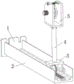
FIG. 1 is a schematic view of the overall structure of a tension apparatus and a control system for manufacturing electric wires and cables according to the present invention;
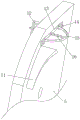
FIG. 2 is a schematic view of a tension adjusting rail structure of a tension apparatus and a control system for manufacturing electric wires and cables according to the present invention;
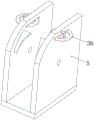
FIG. 3 is a schematic view of a part of the tension apparatus and control system for manufacturing electric wires and cables according to the present invention;
FIG. 4 is a schematic view of a mounting plate structure of a tension device and a control system for manufacturing electric wires and cables according to the present invention;
FIG. 5 is a schematic view of a structure of a tension device and a control system for manufacturing electric wires and cables according to the present invention;
FIG. 6 is a schematic view of a partial structure of a pulley of a tension apparatus and a control system for manufacturing electric wires and cables according to the present invention;
FIG. 7 is a schematic view of a clamping sleeve structure of a tensioning device and a control system for manufacturing electric wires and cables according to the present invention;
FIG. 8 is a schematic view of a clamp ring structure of a tension apparatus and a control system for manufacturing electric wires and cables according to the present invention;
fig. 9 is a schematic structural view of a friction reducing wheel of a tension device and a control system for producing wires and cables according to the present invention.
In the figure: the device comprises a connecting plate 1, a stretching adjusting rail 2, a sliding frame 3, a supporting rod 4, a mounting plate 5, a wheel groove 6, a gear bar 7, a guide wheel 8, a limit gear 9, a motor 10, a guide angle plate 11, a supporting frame 12, an operation opening 13, an elastic rod 14, an annular elastic strip 15, an adjustable supporting threaded rod 16, a rotating wheel 17, a rod hole 18, a connecting rod 19, an adjusting block 20, a rotating rod 21, a spring 22, a sliding rod 23, a corner limit block 24, a wheel frame 25, a clamping wheel 26, a limit block 27, a connecting block 28, a force guide rod 29, a wire clamping sleeve 30, an anti-skid thread 31, a clamping rod 32, a clamping block 33, a wire clamping ring 34, an anti-skid protrusion 35 and a friction reducing wheel 36.
Detailed Description
The technical solutions in the embodiments of the present invention will be clearly and completely described below with reference to the drawings in the embodiments of the present invention, and it is obvious that the described embodiments are only a part of the embodiments of the present invention, and not all of the embodiments.
Example 1:
referring to fig. 1-7, a tensioning device and a control system for wire and cable production, comprising a mounting plate 5, wherein the mounting plate 5 is U-shaped, the outer wall of one side of the mounting plate 5 is connected with a motor 10 through a bolt, one end of the output shaft of the motor 10 is connected with a shaft rod through a bolt, the outer wall of the shaft rod is connected with a rotating wheel 17 through a bolt, the outer wall of the rotating wheel 17 is provided with a plurality of rod holes 18 distributed equidistantly, the inner wall of the rod hole 18 is inserted with a connecting rod 19, both ends of the connecting rod 19 are welded with a sliding rod 23, one end of the sliding rod 23 is provided with a limiting plate, the outer wall of the sliding rod 23 is slidably connected with an adjusting block 20, the outer wall of the top of the adjusting block 20 is welded with a corner limiting block 24, the adjusting block 20 is rotatably connected with a rotating rod 21, one end of the rotating rod 21 is welded with a wheel carrier 25, the inner wall of the wheel carrier 25 is rotatably connected with a wheel rod, and the outer wall of the wheel rod is rotatably connected with a clamping wheel 26 through a bearing, the outer wall of one side of the wheel frame 25 is connected with a connecting block 28 through a bolt, a wire clamping sleeve 30 is inserted into one end of the connecting block 28, the wire clamping sleeve 30 is connected with the connecting block 28 in a sliding mode, a round hole is formed in the outer wall of the wire clamping sleeve 30, a force guide rod 29 is inserted into the inner wall of the round hole, one end of the force guide rod 29 is welded with the outer wall of the wheel frame 25, a wire clamping ring 34 is welded to the other end of the force guide rod 29, the wire clamping ring 34 is semi-annular, a plurality of anti-skidding protrusions 35 are arranged on the outer wall of one side of the wire clamping ring 34, the wire clamping sleeves 30 and the wire clamping ring 34 are symmetric in pairs on two sides of the rotating wheel 17, a clamping rod 32 is welded to the outer wall of one side of the wire clamping sleeve 30, the clamping rod 32 penetrates through the wire clamping ring 34, the clamping rod 32 is connected with the wire clamping ring 34 in a sliding mode, a clamping block 33 is arranged at one end of the clamping rod 32, an inclined plane is arranged on the outer wall of one side of the clamping block 33, and anti-skidding patterns 31 are arranged on the outer wall of one side of the wire clamping sleeve 30.
In the invention, the outer wall of the sliding rod 23 is sleeved with the spring 22, and the spring 22 is positioned between the adjusting block 20 and the connecting rod 19.
The outer wall of the wheel rod of the invention is positioned at two sides of the clamping wheel 26 and is connected with a limiting block 27 through a bolt.
The outer wall of the mounting plate 5 is provided with an operation opening 13, the outer wall of one side of the mounting plate 5 is connected with a support frame 12 through a bolt, the outer wall of the support frame 12 is rotatably connected with an adjustable support threaded rod 16, and one end of the adjustable support threaded rod 16 is provided with a rotating handle.
According to the invention, the outer wall of one side of the mounting plate 5 is connected with an elastic rod 14 through a bolt, an annular elastic strip 15 is welded on the outer wall of the elastic rod 14, an adjustable supporting threaded rod 16 penetrates through the operation opening 13, and one end of the adjustable supporting threaded rod 16 abuts against the outer wall of the annular elastic strip 15.
In the invention, the adjacent outer walls of the mounting plates 5 are connected with guide angle plates 11 through bolts.
According to the invention, the outer wall of the bottom of the mounting plate 5 is connected with a support rod 4 through a bolt, the outer wall of the bottom of the support rod 4 is connected with a sliding frame 3 through a bolt, and guide wheels 8 are arranged on two sides of the sliding frame 3.
According to the invention, a sliding frame 3 is connected with a stretching adjusting rail 2 in a sliding manner, a wheel groove 6 is arranged on the stretching adjusting rail 2, the inner wall of the bottom of the stretching adjusting rail 2 is connected with a gear rack 7 through a bolt, the outer wall of one side of the stretching adjusting rail 2 is connected with a connecting plate 1 through a bolt, the inner wall of the sliding frame 3 is connected with a limiting gear 9 in a rotating manner, the limiting gear 9 is meshed with the gear rack 7, a control motor is arranged on the limiting gear 9, and the control motor is electrically connected with a controller.
In the invention, the inner wall of the operation opening 13 is rotatably connected with a friction reducing wheel 36, and the friction reducing wheel 36 replaces the annular elastic strip 15.
The invention provides a use method of a tensioning device for producing wires and cables, which comprises the following steps:
t1: firstly, the motor 10 drives the rotating wheel 17 to rotate, the rotating wheel 17 is provided with a plurality of clamping wheels 26, clamping sleeves 30, clamping rings 34 and other components, in a normal state, the clamping sleeves 30 and the clamping rings 34 positioned on two sides of the rotating wheel 17 are in an open state, along with the rotation of the rotating wheel 17, the clamping wheels 26 firstly contact the guide angle plate 11, under the action of the guide angle plate 11, the components in the open state, such as the clamping sleeves 30 and the like, are close to the top end of the rotating wheel 17, cables enter from the open openings of the clamping sleeves 30, and the cables are locked along with the closing of the clamping sleeves 30 and the clamping rings 34.
T2: then when the clamping sleeve 30 moves to the topmost end along with the rotating wheel 17, the symmetrical clamping sleeve 30 and the clamping ring 34 are closed under the extrusion force of the annular elastic strip 15 to clamp the cable, and after the clamping sleeve leaves the extrusion range of the annular elastic strip 15, the power is released; at the moment, the next group of clamping sleeves 30 is just extruded by the annular elastic strip 15 to clamp the cable, and continuous traction force is generated on the cable through the force transmission of each group of clamping rings 34 and the clamping sleeves 30, so that the supporting threaded rod 16 can be adjusted to abut against the annular elastic strip 16 for adjusting the tightness of clamping.
T3: finally, when the rotating wheel 17 rotates to pull the cable, the controller receives an electric signal and transmits the electric signal to the control motor according to an operation instruction, the control motor drives the limit gear 9 to rotate, the limit gear 9 and the gear strip 7 complete the movement of the sliding frame 3 in the stretching adjusting rail 2, and the stretching force when the cable is pulled is adjusted.
Example 2:
referring to fig. 8, a tension apparatus and a control system for manufacturing electric wires and cables, this embodiment further includes a friction reducing wheel 36 rotatably connected to an inner wall of the operation opening 13, in which the friction reducing wheel 36 replaces the annular elastic strip 15
The above description is only for the preferred embodiment of the present invention, but the scope of the present invention is not limited thereto, and any person skilled in the art should be considered to be within the technical scope of the present invention, and the technical solutions and the inventive concepts thereof according to the present invention should be equivalent or changed within the scope of the present invention.
Claims (10)
1. The tensioning equipment and the control system for the production of the wires and the cables comprise a mounting plate (5) and are characterized in that the mounting plate (5) is arranged in a U shape, a motor (10) is fixedly connected to the outer wall of one side of the mounting plate (5), a shaft rod is fixedly connected to one end of an output shaft of the motor (10), a rotating wheel (17) is fixedly connected to the outer wall of the shaft rod, a plurality of rod holes (18) are formed in the outer wall of the rotating wheel (17) and distributed equidistantly, a connecting rod (19) is inserted into the inner wall of each rod hole (18), sliding rods (23) are fixedly connected to the two ends of each connecting rod (19), a limiting plate is arranged at one end of each sliding rod (23), an adjusting block (20) is slidably connected to the outer wall of each sliding rod (23), a corner limiting block (24) is fixedly connected to the outer wall of the top of each adjusting block (20), and a rotating rod (21) is rotatably connected to each adjusting block (20), and one end of the rotating rod (21) is fixedly connected with a wheel frame (25), the inner wall of the wheel frame (25) is rotatably connected with a wheel rod, the outer wall of the wheel rod is rotatably connected with a clamping wheel (26), the outer wall of one side of the wheel frame (25) is fixedly connected with a connecting block (28), one end of the connecting block (28) is inserted with a wire clamping sleeve (30), the wire clamping sleeve (30) is slidably connected with the connecting block (28), the outer wall of the wire clamping sleeve (30) is provided with a round hole, the inner wall of the round hole is inserted with a force guide rod (29), one end of the force guide rod (29) is welded with the outer wall of the wheel frame (25), the other end of the force guide rod (29) is fixedly connected with a wire clamping ring (34), the wire clamping ring (34) is arranged in a semi-ring shape, the outer wall of one side of the wire clamping ring (34) is provided with a plurality of anti-skid protrusions (35), the wire clamping sleeves (30) and the wire clamping ring (34) are symmetrical to each other at two sides of the rotating wheel (17), the anti-skid thread clamping device is characterized in that a clamping rod (32) is fixedly connected to the outer wall of one side of the thread clamping sleeve (30), the clamping rod (32) penetrates through the thread clamping ring (34), the clamping rod (32) is connected with the thread clamping ring (34) in a sliding mode, a clamping block (33) is arranged at one end of the clamping rod (32), an inclined surface is arranged on the outer wall of one side of the clamping block (33), and anti-skid threads (31) are arranged on the outer wall of one side of the thread clamping sleeve (30).
2. The tensioning equipment and the control system for the wire and cable production as claimed in claim 1, wherein the outer wall of the sliding rod (23) is sleeved with a spring (22), and the spring (22) is located between the adjusting block (20) and the connecting rod (19).
3. The tensioning device and the control system for wire and cable production as claimed in claim 1, wherein the outer wall of the wheel lever is fixedly connected with limiting blocks (27) at two sides of the clamping wheel (26).
4. The tensioning equipment and the control system for the wire and cable production as claimed in claim 1, wherein the outer wall of the mounting plate (5) is provided with an operation opening (13), the outer wall of one side of the mounting plate (5) is fixedly connected with a support frame (12), the outer wall of the support frame (12) is rotatably connected with an adjustable support threaded rod (16), and one end of the adjustable support threaded rod (16) is provided with a rotating handle.
5. The tensioning device and the control system for wire and cable production as claimed in claim 4, wherein the outer wall of one side of the mounting plate (5) is fixedly connected with an elastic rod (14), the outer wall of the elastic rod (14) is fixedly connected with an annular elastic strip (15), the adjustable supporting threaded rod (16) passes through the operation opening (13), and one end of the adjustable supporting threaded rod (16) abuts against the outer wall of the annular elastic strip (15).
6. The tensioning device and control system for the production of electric wires and cables as claimed in claim 1, wherein a guide angle plate (11) is fixedly connected between the adjacent outer walls of the mounting plate (5).
7. The tensioning device and the control system for wire and cable production as claimed in claim 1, wherein the bottom outer wall of the mounting plate (5) is fixedly connected with the support rod (4), the bottom outer wall of the support rod (4) is fixedly connected with the sliding frame (3), and guide wheels (8) are arranged on two sides of the sliding frame (3).
8. The tensioning device and the control system for wire and cable production according to claim 7, wherein the sliding frame (3) is slidably connected with the stretching adjusting rail (2), the stretching adjusting rail (2) is provided with a wheel groove (6), the bottom inner wall of the stretching adjusting rail (2) is fixedly connected with a rack (7), the outer wall of one side of the stretching adjusting rail (2) is fixedly connected with the connecting plate (1), the inner wall of the sliding frame (3) is rotatably connected with a limit gear (9), the limit gear (9) is meshed with the rack (7), the limit gear (9) is provided with a control motor, and the control motor is electrically connected with a controller.
9. The tensioning device and the control system for the wire and cable production as claimed in claim 5, wherein the inner wall of the operation opening (13) is rotatably connected with a friction reducing wheel (36), and the friction reducing wheel (36) replaces the annular elastic strip (15).
10. The use method of the self-cleaning internal cyclone membrane separation device for purifying the wastewater is characterized by comprising the following steps of:
t1: firstly, a motor (10) drives a rotating wheel (17) to rotate, a plurality of clamping wheels (26), clamping sleeves (30), clamping rings (34) and other components are arranged on the rotating wheel (17), in a normal state, the clamping sleeves (30) and the clamping rings (34) which are positioned on two sides of the rotating wheel (17) are in an open state, along with the rotation of the rotating wheel (17), the clamping wheels (26) firstly contact a guide angle plate (11), and under the action of the guide angle plate (11), the components in the open state, such as the clamping sleeves (30) and the like, are close to the inner side, when the clamping sleeves (30) are close to the top end of the rotating wheel (17), a cable enters from an open gap of the clamping sleeves (30), and along with the closing of the clamping sleeves (30) and the clamping rings (34), the cable is locked.
T2: then when the clamping sleeve (30) moves to the top end along with the rotating wheel (17), the symmetrical clamping sleeve (30) and the clamping ring (34) are closed under the extrusion force of the annular elastic strip (15) to clamp the cable, and after the clamping sleeve leaves the extrusion range of the annular elastic strip (15), the power is released; at the moment, the next group of clamping sleeves (30) is just extruded by the annular elastic strip (15) to clamp the cable, continuous traction force is generated on the cable through force transmission of each group of clamping rings (34) and the clamping sleeves (30), and the adjustable supporting threaded rod (16) abuts against the annular elastic strip (16) and is used for adjusting the tightness of clamping.
T3: and finally, when the rotating wheel (17) rotates and pulls the cable, the controller receives an electric signal and transmits the electric signal to the control motor according to an operation instruction, the control motor drives the limit gear (9) to rotate, the limit gear (9) and the gear rack (7) complete the movement of the sliding frame (3) in the stretching adjusting rail (2), and the stretching force when the cable is pulled is adjusted.
Priority Applications (1)
| Application Number | Priority Date | Filing Date | Title |
|---|---|---|---|
| CN202110310670.3A CN113443508B (en) | 2021-03-23 | 2021-03-23 | Tensioning equipment and control system for wire and cable production |
Applications Claiming Priority (1)
| Application Number | Priority Date | Filing Date | Title |
|---|---|---|---|
| CN202110310670.3A CN113443508B (en) | 2021-03-23 | 2021-03-23 | Tensioning equipment and control system for wire and cable production |
Publications (2)
| Publication Number | Publication Date |
|---|---|
| CN113443508A true CN113443508A (en) | 2021-09-28 |
| CN113443508B CN113443508B (en) | 2023-01-17 |
Family
ID=77809237
Family Applications (1)
| Application Number | Title | Priority Date | Filing Date |
|---|---|---|---|
| CN202110310670.3A Active CN113443508B (en) | 2021-03-23 | 2021-03-23 | Tensioning equipment and control system for wire and cable production |
Country Status (1)
| Country | Link |
|---|---|
| CN (1) | CN113443508B (en) |
Citations (10)
| Publication number | Priority date | Publication date | Assignee | Title |
|---|---|---|---|---|
| JPS5798466A (en) * | 1980-12-08 | 1982-06-18 | Nippon Telegr & Teleph Corp <Ntt> | Cable traction machine |
| FR2663795A1 (en) * | 1990-06-22 | 1991-12-27 | France Telecom | METHOD FOR PLACING A CABLE INSIDE A HIGH LENGTH CONDUIT AND DEVICE FOR IMPLEMENTING SAID METHOD |
| CN1238739A (en) * | 1996-11-28 | 1999-12-15 | 奈克斯特罗姆·霍尔丁公司 | Capstan arrangement for cable treatment plant |
| CN109775435A (en) * | 2019-01-31 | 2019-05-21 | 广东拓斯达科技股份有限公司 | A kind of copper wire clamp driving mechanism and the copper wire stack equipment for having the mechanism |
| CN111498586A (en) * | 2020-04-21 | 2020-08-07 | 江苏千瑞纺织科技有限公司 | Spinning thread conveying device for jacquard weaving machine |
| CN111573412A (en) * | 2020-05-31 | 2020-08-25 | 胡晓霖 | Wire harness traction equipment |
| CN111717723A (en) * | 2020-05-27 | 2020-09-29 | 杭州优朴信息技术有限公司 | Cable conveyer of roller type |
| CN111847100A (en) * | 2020-07-27 | 2020-10-30 | 南京蔚特尔智能科技有限公司 | Continuous supply equipment and method for laying communication cable |
| CN112010120A (en) * | 2020-08-27 | 2020-12-01 | 安徽华海特种电缆集团有限公司 | Mobile marine cable for traveling crane |
| CN212304489U (en) * | 2020-07-01 | 2021-01-05 | 贾兴林 | Cable pulling device for power distribution network |
-
2021
- 2021-03-23 CN CN202110310670.3A patent/CN113443508B/en active Active
Patent Citations (10)
| Publication number | Priority date | Publication date | Assignee | Title |
|---|---|---|---|---|
| JPS5798466A (en) * | 1980-12-08 | 1982-06-18 | Nippon Telegr & Teleph Corp <Ntt> | Cable traction machine |
| FR2663795A1 (en) * | 1990-06-22 | 1991-12-27 | France Telecom | METHOD FOR PLACING A CABLE INSIDE A HIGH LENGTH CONDUIT AND DEVICE FOR IMPLEMENTING SAID METHOD |
| CN1238739A (en) * | 1996-11-28 | 1999-12-15 | 奈克斯特罗姆·霍尔丁公司 | Capstan arrangement for cable treatment plant |
| CN109775435A (en) * | 2019-01-31 | 2019-05-21 | 广东拓斯达科技股份有限公司 | A kind of copper wire clamp driving mechanism and the copper wire stack equipment for having the mechanism |
| CN111498586A (en) * | 2020-04-21 | 2020-08-07 | 江苏千瑞纺织科技有限公司 | Spinning thread conveying device for jacquard weaving machine |
| CN111717723A (en) * | 2020-05-27 | 2020-09-29 | 杭州优朴信息技术有限公司 | Cable conveyer of roller type |
| CN111573412A (en) * | 2020-05-31 | 2020-08-25 | 胡晓霖 | Wire harness traction equipment |
| CN212304489U (en) * | 2020-07-01 | 2021-01-05 | 贾兴林 | Cable pulling device for power distribution network |
| CN111847100A (en) * | 2020-07-27 | 2020-10-30 | 南京蔚特尔智能科技有限公司 | Continuous supply equipment and method for laying communication cable |
| CN112010120A (en) * | 2020-08-27 | 2020-12-01 | 安徽华海特种电缆集团有限公司 | Mobile marine cable for traveling crane |
Non-Patent Citations (1)
| Title |
|---|
| 陈宇晓: "电缆输送机的设计与制造", 《光纤与电缆及其应用技术》 * |
Also Published As
| Publication number | Publication date |
|---|---|
| CN113443508B (en) | 2023-01-17 |
Similar Documents
| Publication | Publication Date | Title |
|---|---|---|
| CN112978482A (en) | Take-up reel for preventing cable from winding during winding for power electrical engineering and use method | |
| CN113241676B (en) | Electric power construction tensioner bullwheel | |
| CN115360641A (en) | Auxiliary laying device and method for underground cable in power engineering | |
| CN113443508A (en) | Tensioning equipment and control system for wire and cable production | |
| CN117410884B (en) | Cable erection device for electromechanical installation | |
| CN115296212B (en) | Cable trunk line laying device for building construction site | |
| CN115410777B (en) | Bare conductor adhesive tape winding device | |
| CN215557915U (en) | Short-disc steel wire recovery device | |
| CN109384159B (en) | Traction device of vertical lifting system | |
| CN211830454U (en) | Wiring device for rotating motor in large motor driving equipment | |
| CN110596843B (en) | Cable bundling device | |
| KR102163990B1 (en) | Wire drive device for stage equipment | |
| CN221543621U (en) | Take-up device for network engineering | |
| CN219247348U (en) | Threading construction device for building electrical engineering | |
| CN214879248U (en) | Network engineering wiring construction device | |
| CN221680442U (en) | Cable laying machine with guiding function | |
| CN214896936U (en) | Traffic safety supervisory equipment convenient to installation | |
| CN221116414U (en) | Automatic combination formula cable paying out machine | |
| CN117595141B (en) | Power grid operation robot and working method thereof | |
| CN220392986U (en) | Cable wire harness device | |
| CN217577601U (en) | Papermaking paper leading rope traction device | |
| CN212769101U (en) | Doubling winder guiding mechanism | |
| CN118249251B (en) | Wire erecting device for power engineering construction | |
| CN219642605U (en) | A quick braiding equipment for cable processing | |
| CN219497430U (en) | Pipe winch for cable production |
Legal Events
| Date | Code | Title | Description |
|---|---|---|---|
| PB01 | Publication | ||
| PB01 | Publication | ||
| SE01 | Entry into force of request for substantive examination | ||
| SE01 | Entry into force of request for substantive examination | ||
| GR01 | Patent grant | ||
| GR01 | Patent grant |