CN1134360C - Steering column crash system - Google Patents
Steering column crash system Download PDFInfo
- Publication number
- CN1134360C CN1134360C CNB998061859A CN99806185A CN1134360C CN 1134360 C CN1134360 C CN 1134360C CN B998061859 A CNB998061859 A CN B998061859A CN 99806185 A CN99806185 A CN 99806185A CN 1134360 C CN1134360 C CN 1134360C
- Authority
- CN
- China
- Prior art keywords
- carriage
- steering hardware
- chassis
- clamping element
- fracture
- Prior art date
- Legal status (The legal status is an assumption and is not a legal conclusion. Google has not performed a legal analysis and makes no representation as to the accuracy of the status listed.)
- Expired - Fee Related
Links
Images


Classifications
-
- B—PERFORMING OPERATIONS; TRANSPORTING
- B62—LAND VEHICLES FOR TRAVELLING OTHERWISE THAN ON RAILS
- B62D—MOTOR VEHICLES; TRAILERS
- B62D1/00—Steering controls, i.e. means for initiating a change of direction of the vehicle
- B62D1/02—Steering controls, i.e. means for initiating a change of direction of the vehicle vehicle-mounted
- B62D1/16—Steering columns
- B62D1/18—Steering columns yieldable or adjustable, e.g. tiltable
- B62D1/19—Steering columns yieldable or adjustable, e.g. tiltable incorporating energy-absorbing arrangements, e.g. by being yieldable or collapsible
- B62D1/195—Yieldable supports for the steering column
Landscapes
- Engineering & Computer Science (AREA)
- Chemical & Material Sciences (AREA)
- Combustion & Propulsion (AREA)
- Transportation (AREA)
- Mechanical Engineering (AREA)
- Steering Controls (AREA)
Abstract
The invention relates to a steering device for motor vehicles, comprising a steering shaft that is guided by a guide box (3) which is connected to a retaining console and, for example, clamped. The console has at least one sliding surface (8) along the axis of the shaft (1) which allows for a displacement path (20) with respect to the chassis (18) in the case of a collision. Clamping means (17) are provided for axial retention of the console (6) in an initial position of said displacement path (20). Preferably, the clamping device is made from a screwed connection (17) or, advantageously, from only two screwed connections without a separate console guide. This simplifies the construction of the steering device to a considerable extent, enabling it to be assembled in a quick and economical manner.
Description
The present invention relates to a kind of steering hardware that is used for self-propelled vehicle with steering shaft.
The steering hardware that is used for self-propelled vehicle is often made two parts can doing mutual displacement, thereby avoids steering hardware to jeopardize chaufeur in positive car accident, and this moment, steering hardware deformed when health and bearing circle collision, and with impact energy absorption.In known mechanism, the steering shaft sleeve pipe that normally will hold the steering shaft of bearing circle side is arranged in the housing, and this housing is fixed on the desired location by the relative car chassis of bolt.The structure of described bolt can guarantee that when bump the axle head of bearing circle side and institute's bonded assembly housing carriage move certain stroke vertically under clamped condition.Impact energy correspondingly is absorbed by clamping mechanism.In order in impact events, to obtain uniform energy absorbing, also between shaft part that vertically moves and car chassis, be provided with energy absorbing element.A kind of energy absorbing element is to adopt the lath that can rupture to constitute, for example referring to british patent specification GB1390889.
The shortcoming of known steering-column crash system is that the one side disruptive force can not be independent of energy absorbing power basically and determine in very wide scope.On the other hand absorption characteristic can not be accurately again terrain pre-determine.
Task of the present invention is, a kind of crash system that is used for Steering gear mechanism is provided, and it can avoid the shortcoming of prior art.This task is particularly in realizing a kind of steering-column crash system, and it can realize the disruptive force determined, but and realizes the energy absorbing determined with reproducing characteristic.This mechanism installs simple and can make economically in addition.
The present invention is this steering hardware that is used for self-propelled vehicle to the solution body of above task, has a steering shaft by guiding case guiding, described guiding case adopts clamping mode to be connected with a carriage, carriage wherein has at least one sliding surface along axis arranged, the relative chassis of described carriage allows a shift motion, and the both sides at axis are provided with clamping element, be used for carriage is axially fixed in the initial position of shift motion, and it is a fracture hoop is fixing with described clamping element, make the relative chassis of sliding surface of holder flange clamped, particularly need not to adopt independently cradle guide, feature of the present invention is, described carriage, guiding case and fracture hoop constitute as plate, and the fracture hoop has a fracture bar between the otch slideway on the axis direction, one end of wherein said fracture bar has fixed plate, its bar that will rupture is fixed on the carriage, and fix to clamp both sides at axis like this by the described clamping element hoop that will rupture, be about to rupture case and described fracture bar and fixed plate are arranged on the centre of described clamping element.
In device of the present invention, its structure realizes that so promptly disruptive force can make the steering shaft displacement and separate with energy absorbing power in impact events.
So clamping part separates in impact events immediately, wherein so-called broken pieces is had an effect, thereby makes Impact energy pass to energy absorbing element basically after the clamping mechanism fracture.This structure can realize the shift motion of energy absorbing through determining, can not be subjected to the influence of uncertain gripping power basically, and sorption can be determined targetedly in advance by the structure of absorber element.
An embodiment of described broken pieces realizes in the scope of clamp fixer, wherein most of gripping power acts between shell carriage and the fixing chassis portion, described clamp fixer by the planar section that compresses mutually clamping and with respect to direction of slip a little inclination is arranged, that is to say, constitute a specific angle of wedge, thereby reduce initial gripping power at once when very short shift motion occurring, its mode is that two chamfered portions are made slide relative according to amounts of angular deflection.In this way, can be when bump takes place, produced 1/tens millimeters displacement after, promptly cause the clamping mechanism fracture, and displacement subsequently can be by uncertain gripping power decision.The described housing carriage that is fixed on the steering shaft sleeve pipe links to each other with the chassis by a fracture hoop.The structure of this fracture hoop has mainly been determined the degree and the process of energy absorption characteristics.Corresponding size by this split pieces is selected, can be according to the best mode design energy absorption characteristic of protection chaufeur.
Another kind of preferred construction is, in the sliding surface scope that compresses mutually, both sides on the plane are provided with protuberance, and this protuberance supports on a very short stroke mutually, make sliding surface mainly be made of the short range contact zone of protuberance, and when being subjected to displacement, promptly under the situation of fracture, a protuberance after very short stroke, several millimeters stroke for example, promptly go up landing, thereby in impact events, produce desirable fracture from another protuberance.In another simple especially preferred embodiment, the constituted mode of broken pieces is, makes the stepped clamping surface that is oppositely arranged at least in the part of the planar section that is clamped, and makes gripping power disappear behind the shift motion of a weak point.
The scheme of the Steering gear mechanism of the crash system that a kind of cost is low especially and compact conformation, have energy absorption characteristics is, steering shaft is arranged in the guiding case, this guiding case is captiveed joint with a carriage, wherein the bracket side mask has the sliding surface of flange shape, and this sliding surface for example is clamped on the car chassis by bolt.Described clamping mechanism can be under impact events, and it is mobile that Steering gear is deformed together with carriage, for example moves some centimetres.Described energy absorbing element is captiveed joint with the chassis on the one hand, links to each other with steering shaft through carriage in the place that energy absorbing takes place on the other hand.Described absorber element preferably adopts the plate with split pieces to constitute, and described split pieces for example constitutes hoop shape as the fracture hoop, is installed between holder flange and the chassis.This embodiment has very big advantage, and the fixed sturcture on the chassis only has two connecting elements, preferably two bolts.This scheme simplifies the structure greatly, and allows to assemble fast, thereby overall cost is produced favorable influence.The screw-down torque of bolt is preferably between the 15-35Nm.This very simple organization plan particularly entire mechanism is only fixed with two bolt of rear end plates, does not have other carrier structure, can be used in the disposable application scenario, need not to adopt foregoing special-purpose broken pieces.In this case, the definite division between disruptive force and the energy absorbing is very not clear and definite, but this mechanism can realize with very low cost.
The present invention is further illustrated for contrast accompanying drawing illustrated embodiment below.
Fig. 1 represents that Steering gear of the present invention clamps the lateral plan of mechanism,
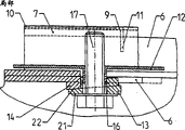
Fig. 2 represents the cutaway view of clamping mechanism shown in Figure 1,
Fig. 2 a represents the part sectional view of clamp fitting part,
Fig. 3 a represents the local longitudinal sectional view of a clamping surface structure, and its clamping surface is a bevelled,
The partial top view of clamping mechanism shown in Fig. 3 b presentation graphs 3a,
What Fig. 4 represented is that impact is measured diagram of curves, demonstrates the characteristic curve of prior art,
What Fig. 5 represented is that impact is measured diagram of curves, demonstrates characteristic curve of the present invention,
Fig. 6 represents the local longitudinal sectional view of another clamping surface structure, is provided with the protuberance as separator between its sliding surface,
Fig. 7 represents the local longitudinal sectional view of another clamping surface structure, and it clamps the position is stepped,
Steering shaft with steering shaft axis 1 links to each other with bearing circle 2, and is installed in the guiding case 3, and this guiding case is captiveed joint with an analog bracket 6 as shown in Figure 1, for example adopts clamping mode.This guiding case 3 can also be made height adjustment and/or length adjustment.Described analog bracket 6 is fixed on the car chassis 18.Make retraction displacement when axle 1 structure can be implemented in bump, and described carriage 6 is in impact events, greatly in being no more than 50 millimeters scope relatively chassis 18 make longitudinal travel.Described carriage 6 is preferably made U-shaped, and at least in part the guiding case of being fixed 3 is surrounded.Supporting a guide 4 for example is fixed between the bracket portion 6 by connecting element 5.For example there is the sliding surface 8 that is arranged on both sides the side of carriage 6, and a long and narrow seam 20 is arranged on this sliding surface.This long and narrow seam constitutes sliding joint, and its effect is to hold connecting element 13,16,17, as screw or fastening bolt 17 (preferably).Carriage 6 is preferably made plate, and when it adopts stamped, and when constituting as bool, its manufacturing cost is minimum.The advantage on cost, its another advantage is that its bending stiffness is for example higher than welded.
Carriage 6 can be fixed on the chassis 18 by fastening bolt 17, its mode is in impact events, and steering shaft can produce displacement together with guiding case 3 in the length range of sliding joint.Even if in order to make clamping mechanism fracture immediately in very little shift motion, in the end of sliding joint 20, be provided with a clamping surface 22 that is positioned at bracket side on initial clamped position, its advantage is to be in tilted layout with an angle of wedge 15 relative voussoirs 14.The bolt side is another lozenges 22, and it is as the skidding 13 same inclined-planes with angle of wedge 15 that adopt.Described skidding 13 is preferably in the mobile situation and can slides in sliding joint 20.Because clamping surface is not in 90 ° position with respect to clamping direction, so even if in very short shift motion, can make gripping power cause fracture immediately yet.The suitable angle of wedge is 2 ° to 15 °, preferred 3 ° to 8 °.
Carriage 6 for example can directly be fixed on the chassis 18 with bolt 17, and wherein skidding 13 is preferably in the first side of bolt a pad 21 is set.In Fig. 2, express the cutaway view of this structure, wherein demonstrate the optimal way that interfixes on the both sides and the chassis 18 of axis 1.Described voussoir 14 can directly process in carriage 6 together with its wedge surface.But this voussoir also can adopt simpler and more accurate method manufacturing, is about to it as the independently part manufacturing of gasket shape, and is fixed on the carriage 6.
In order to obtain determining the energy absorption characteristics of definition, also be provided with an energy absorbing element 9, this element preferably constitutes as the plate with fracture bar and fixed plate 9.The described plate 7 preferred clips 7 that adopt constitute, and it is centered around the upper position of U-shaped carriage 6, and is fixed on the chassis 18 with the clamping mechanism of carriage 6, and remains on the initial position.Split pieces 9 is preferably disposed on the plate of upper plane U-shaped of fracture hoop 7.Wherein split pieces 9 is pressed on the carriage 6 as a part of bending of fracture hoop 7, and split pieces 9 can be fixed by relative carriage, and is for example clamped or fixing by being welded to connect 11.Fracture bar with fixed plate 9 is between the otch slideway, and the material thickness by fracture hoop sheet material, by strength of material and by having the rolling width of corresponding theoretical running radius of tire, adjusts.For example also can change the rolling width in case of necessity, thereby to the diagram of curves change of absorption power.
The structure of above-described whole clamping mechanism is, the sliding surface 12 of fracture hoop 7 is clamped between holder flange 6,8 and the chassis 18, and its special advantage is, need not to unite to use special broken pieces 13,14,22,26,27,29.This structure can realize the assembling of plain mode, and it has low cost structure, and good operation characteristic and higher structural stability, particularly this structure optimization adopt two bolts 17 to be fixed on the chassis 18.Device of the present invention need not to use independently that cradle guide can realize, thereby simplifies the structure greatly.A kind of simple especially structure of this device only clamps with two bolts 17, and need not to use independently cradle guide as mentioned above.
The structure of described skidding 13 shown in Fig. 3 a is that when carriage 6 moved with respect to skidding 13, the part of skidding in sliding joint 20 can be slided but can not be reversed.Described wedge surface 22 can move between voussoir 14 and skidding 13, and this moment, it played the effect of broken pieces, is separated from each other and causes the clamping mechanism fracture, and gripping power wherein or energy absorbing are by the decision of fracture bar.
Described fracture hoop 7 in fixed range preferably both sides have the plate tongue structure, it is fixed on the chassis 18 between the slip flange surface 8 of chassis 18 and carriage 6 and by bolt 17.In impact events, carriage 6 equals sliding joint length 20 together with the maximum amount of movement of voussoir 14, and described voussoir breaks away from from fixing skidding 13, and fracture hoop 7 keeps motionless simultaneously, and the split pieces 9 that is fixed on the bracket portion 6 then ruptures.In order to set up seamless connectivity between skidding 13 and fracture hoop 7, the Kongzui on fracture hoop 7 has flange 16 well, makes skidding 13 link to each other with flange 16, sees shown in Fig. 2 a.Fig. 3 b expresses the birds-eye view of this structure, wherein can see sliding joint 20.
The another kind of scheme of improving the duplicability of fracture characteristics is described clamping surface 22, i.e. bevelled skidding surface 13 and the specific surface treatment of voussoir surface 14 processes.Described surface treatment can be on purpose plucking and/or plated film and/or lubricated.
The screw-down torque of fastening bolt preferably is set in 15 to 35Nm the scope with the moment determinator.Express the broken curve figure of measured disruptive force characteristic in Fig. 4, its stroke is 45mm, and bolt wherein is fastening with the screw-down torque of 25Nm.Can find out also that in the drawings disruptive force surpasses 9000N, and about 5mm than long travel after just descend, but have the remaining gripping power of a higher relatively about 6000N to keep uncertain effect always, up to the stroke end of 45mm.Under same test condition, the diagram of curves that Fig. 5 expresses is the characteristic of structure shown in Figure 1.Described bolt is set on the moment of 25Nm equally.Disruptive force reaches 6000N, and falls suddenly immediately after definite stroke of about 1mm, thereby makes the disruptive force of the broken pieces with inclined surface, evenly keeps below the reduced levels of 2000N on the whole stroke of 45mm.In device of the present invention, after of short duration fracture process, absorb energy and can pass through absorber element, preferably adopt split pieces to set with definite, mode reproducible and that can be scheduled to, for example predesignate energy absorbing power and be 1200 to 5500N.
The scheme of the realization broken pieces that another kind is suitable is seen shown in Figure 6, wherein for example is provided with protuberance 26,27 between sliding surface 8,12, thereby sliding surface is kept on initial position from 1/tens millimeters to about 3 millimeters slight distance.Described protuberance 26,27 substantial symmetry are arranged in the both sides of sliding surface, its position can make described protuberance be clamped together relatively, thereby produce very short sliding surface 12, this sliding surface is under situation about moving, that is to say the mutual landing of meeting in impact events, the gripping power effect will be disappeared, make energy absorbing finish in the mode of determining by absorber element 7,9,11.This protuberance for example can be made the boss shape, and is fixed on axis both sides longitudinally with bolt part 17.But according to requirement, several also can be set side by side or tactic boss shape protuberance, and constitute stepped or be arranged on the bevelled surface gripping power friction force and shift motion and whole device size.In this example, skidding 13 for example is to adopt simple pad to realize.But also this boss structure can be arranged in the scope of skidding 13.
In Fig. 7, represented another very favourable and simple broken pieces embodiment.In this embodiment, the surface that is close together mutually and clamps of skidding 13 and initial voussoir 14 is not a wedge shape, but step-like.The step structure definable of this classification stroke that goes out to rupture.This structure can adopt very simple and cheaply mode realize.The above various types of broken pieces can adopt the mode of combining mutually.
Claims (18)
1, the steering hardware that is used for self-propelled vehicle, has a steering shaft by guiding case (3) guiding, described guiding case adopts clamping mode to be connected with a carriage (6), carriage wherein has at least one sliding surface (8) of arranging along axis (1), the relative chassis of described carriage (18) allows a shift motion (20), and the both sides at axis (1) are provided with clamping element (13,16,17), be used for carriage (6) is axially fixed in the initial position of shift motion (20), and with described clamping element (13,16,17) a fracture hoop (7) is fixing, make holder flange (6,8) chassis (18) is clamped relatively for sliding surface (12), particularly need not to adopt independently cradle guide, feature of the present invention is, described carriage (6), guiding case (3) and fracture hoop (7) constitute as plate, and fracture hoop (7) has a fracture bar that is positioned between the otch slideway (10) on the axis direction (1), one end of wherein said fracture bar has fixed plate (9), its bar that will rupture is fixed on the carriage (6), and by described clamping element (13,16,17) hoop (7) that will rupture fixes to clamp both sides in axis (1) like this, be about to the centre that fracture hoop (7) and described fracture bar and fixed plate (9) are arranged on described clamping element (13,16,17).
2, steering hardware as claimed in claim 1 is characterized in that, described clamping element (7,17,18,21) has the screw element (17) on the both sides of axis (1), and its screw-down torque is 20 to 30Nm.
3, steering hardware as claimed in claim 1 is characterized in that, described clamping element (13,16,17) at least one subrange at initial position contains a broken pieces (13,14 with clamping surface (22), 29,30), thus when carriage is mobile along axis direction (19), reduce gripping power.
4, steering hardware as claimed in claim 3 is characterized in that, described broken pieces (13,14,29,30) has step-like clamping surface (29,22).
5, steering hardware as claimed in claim 3 is characterized in that, described broken pieces (13,14,29,30) between sliding surface (8) and chassis (18), have on initial position, with the paired protuberance (26 arranged of mode up and down, 26 ', 27,27 '), make the protuberance (26 of carriage one side, 27) under situation about moving, the protuberance of one side from the chassis (26 ', 27 ') upward landing.
6, steering hardware as claimed in claim 5 is characterized in that, two pairs of described protuberances (26,26 ', 27,27 ') is set at least, and has clamping element (17) therebetween on axis direction (1).
7, steering hardware as claimed in claim 1 is characterized in that, described carriage (6) links to each other with the energy-absorbing element (9,10) that a relative chassis (18) is fixed.
8, steering hardware as claimed in claim 1 is characterized in that, described carriage (6) case (3) that will lead clamps, and have sliding surface (8) and the device (13 that is used for (18) last clamp fitting on both sides on the chassis, 16,17), wherein said clamp fitting adopts engage thread.
9, steering hardware as claimed in claim 1 is characterized in that, described split pieces has a sliding surface (7,12), and this sliding surface is positioned between chassis (18) and the carriage sliding surface (6,8).
10, steering hardware as claimed in claim 1 is characterized in that, described clamping surface (22) constitutes as annular gasket, and wherein upper gasket (14) is fixed on the carriage (6), and lower gasket (13) is fixed on the chassis (18) with clamping element as skidding (13).
11, steering hardware as claimed in claim 1 is characterized in that, described sliding surface (8) has a sliding joint (20) in carriage (6), is used for the guide-localization of clamping element (16,17,13).
12, steering hardware as claimed in claim 1 is characterized in that, at least one clamping surface (22) is carried out surface treatment.
13, steering hardware as claimed in claim 1 is characterized in that, described carriage (6) constitutes as plate.
14, steering hardware as claimed in claim 7 is characterized in that, described energy-absorbing element (9,10) constitutes as fracture hoop (7), and directly is fixed on chassis (18) by clamping element (17) and goes up also leak-tight joint.
15, steering hardware as claimed in claim 1 is characterized in that, other devices (26,27) are set in the scope of described clamping element (13,16,17), makes carriage (6) clamped with elastic type with respect to clamping element and chassis (18).
16, steering hardware as claimed in claim 15, it is characterized in that, on axis direction for separating screw element (17), at carriage (8) be positioned between the surface (7,18) on opposite and be provided with a separator (26,27), under tight condition, at described clamping element (7,17,18,21) produce the clamping of elastic type between.
17, steering hardware as claimed in claim 16 is characterized in that, described separator (26,27) is arranged on the both sides of screw element (17) on axis direction (1).
18, steering hardware as claimed in claim 17 is characterized in that, described separator constitutes as protuberance or boss (26,27).
Applications Claiming Priority (2)
| Application Number | Priority Date | Filing Date | Title |
|---|---|---|---|
| CH1129/1998 | 1998-05-22 | ||
| CH112998 | 1998-05-22 |
Publications (2)
| Publication Number | Publication Date |
|---|---|
| CN1301225A CN1301225A (en) | 2001-06-27 |
| CN1134360C true CN1134360C (en) | 2004-01-14 |
Family
ID=4203177
Family Applications (1)
| Application Number | Title | Priority Date | Filing Date |
|---|---|---|---|
| CNB998061859A Expired - Fee Related CN1134360C (en) | 1998-05-22 | 1999-05-17 | Steering column crash system |
Country Status (7)
| Country | Link |
|---|---|
| US (1) | US6474690B1 (en) |
| EP (1) | EP1077862B1 (en) |
| JP (1) | JP2002516218A (en) |
| CN (1) | CN1134360C (en) |
| DE (1) | DE59904631D1 (en) |
| ES (1) | ES2191427T3 (en) |
| WO (1) | WO1999061298A1 (en) |
Families Citing this family (6)
| Publication number | Priority date | Publication date | Assignee | Title |
|---|---|---|---|---|
| GB2393157B (en) * | 2000-11-08 | 2004-05-12 | Nsk Steering Sys Europ Ltd | Collapsible steering column assembly for a vehicle |
| JP4952875B2 (en) * | 2004-06-04 | 2012-06-13 | 日本精工株式会社 | Steering column device |
| KR100836909B1 (en) * | 2006-07-12 | 2008-06-11 | 현대자동차주식회사 | Impact absorbing system of steering column for vehicle |
| US8430428B2 (en) * | 2009-01-05 | 2013-04-30 | Steering Solutions Ip Holding Corporation | Steering column assembly comprising a mounting capsule |
| DE102009021579A1 (en) * | 2009-05-15 | 2010-11-18 | Thyssenkrupp Presta Ag | Steering column for a motor vehicle |
| DE102010021957A1 (en) * | 2009-05-29 | 2011-01-13 | GM Global Technology Operations, Inc., Detroit | Collapsible steering column construction |
Family Cites Families (20)
| Publication number | Priority date | Publication date | Assignee | Title |
|---|---|---|---|---|
| EP0295378B1 (en) * | 1987-06-19 | 1992-07-22 | Dr.Ing.h.c. F. Porsche Aktiengesellschaft | Mounting comprising a deformation element for a motor vehicle steering column |
| JPH02128679U (en) * | 1989-03-31 | 1990-10-23 | ||
| US5152551A (en) * | 1990-06-28 | 1992-10-06 | Toyoda Gosei Co., Ltd. | Steering wheel having impact absorbing member |
| GB9122962D0 (en) * | 1991-10-30 | 1991-12-18 | Torrington Co | Locking mechanism for a vehicle steering column |
| DE4241391C2 (en) * | 1991-12-20 | 2002-09-12 | Volkswagen Ag | Motor vehicle steering with a telescopic steering spindle, a telescopic protective tube and means for retracting the steering wheel in the event of a crash |
| US5390955A (en) * | 1993-12-23 | 1995-02-21 | Chrysler Corporation | Steering column release capsules |
| JPH08150943A (en) * | 1994-11-30 | 1996-06-11 | Fuji Kiko Co Ltd | Tilt steering column |
| JPH08225079A (en) * | 1995-02-20 | 1996-09-03 | Nippon Seiko Kk | Impact absorbing type steering column |
| FR2737175B1 (en) * | 1995-07-26 | 1997-10-10 | Nacam | ENERGY ABSORPTION AND GUIDANCE DEVICE FOR AUTOMOTIVE VEHICLE STEERING COLUMN |
| JPH0976923A (en) * | 1995-09-13 | 1997-03-25 | Aisin Seiki Co Ltd | Steering device for vehicle |
| EP0769445B1 (en) * | 1995-10-17 | 1999-01-20 | General Motors Corporation | Energy absorbing steering column for motor vehicle |
| FR2748251B1 (en) * | 1996-05-03 | 1998-06-26 | Lemforder Nacam Sa | ACTIVE RETRACTION DEVICE, ON IMPACT, OF A STEERING COLUMN OF A MOTOR VEHICLE |
| US5820163A (en) * | 1996-07-08 | 1998-10-13 | Ford Global Technologies, Inc. | Tilting, telescoping and energy absorbing steering column |
| US5692778A (en) * | 1996-11-14 | 1997-12-02 | General Motors Corporation | Motor vehicle steering column |
| US5787759A (en) * | 1997-02-11 | 1998-08-04 | General Motors Corporation | Position control apparatus for steering column |
| JP3612971B2 (en) * | 1997-12-03 | 2005-01-26 | 日本精工株式会社 | Shock absorbing steering column device |
| US5954363A (en) * | 1997-12-18 | 1999-09-21 | General Motors Corporation | Energy-absorbing steering column for motor vehicle |
| US5984355A (en) * | 1998-03-10 | 1999-11-16 | Chysler Corporation | Steering column angle |
| US5960673A (en) * | 1998-04-02 | 1999-10-05 | Chrysler Corporation | Isolator pad for a steering column |
| US6019391A (en) * | 1998-05-04 | 2000-02-01 | General Motors Corporation | Steering column for motor vehicle |
-
1999
- 1999-05-17 CN CNB998061859A patent/CN1134360C/en not_active Expired - Fee Related
- 1999-05-17 EP EP99917734A patent/EP1077862B1/en not_active Expired - Lifetime
- 1999-05-17 JP JP2000550722A patent/JP2002516218A/en active Pending
- 1999-05-17 WO PCT/CH1999/000209 patent/WO1999061298A1/en active IP Right Grant
- 1999-05-17 ES ES99917734T patent/ES2191427T3/en not_active Expired - Lifetime
- 1999-05-17 US US09/700,368 patent/US6474690B1/en not_active Expired - Fee Related
- 1999-05-17 DE DE59904631T patent/DE59904631D1/en not_active Expired - Lifetime
Also Published As
| Publication number | Publication date |
|---|---|
| JP2002516218A (en) | 2002-06-04 |
| EP1077862A1 (en) | 2001-02-28 |
| EP1077862B1 (en) | 2003-03-19 |
| WO1999061298A1 (en) | 1999-12-02 |
| CN1301225A (en) | 2001-06-27 |
| DE59904631D1 (en) | 2003-04-24 |
| US6474690B1 (en) | 2002-11-05 |
| ES2191427T3 (en) | 2003-09-01 |
Similar Documents
| Publication | Publication Date | Title |
|---|---|---|
| CN1106967C (en) | Steering-column crash system | |
| US9688339B2 (en) | Vehicle provided with leaning-capable vehicle-body frame and two front wheels | |
| CN1107608C (en) | Steering column crash system | |
| US8997602B2 (en) | Position adjustable steering device | |
| JP3727004B2 (en) | Shock absorbing steering device and mounting member used therefor | |
| US5738377A (en) | Shock absorbing plate for a vehicle steering wheel | |
| JP5688029B2 (en) | Car axle | |
| JP4840128B2 (en) | A car equipped with a knee bolster and a knee bolster as well as a passenger limb protection method | |
| EP2540534A1 (en) | Suspension structure, bush structure and suspension characteristic adjusting method | |
| EP1223096A1 (en) | Steering column assembly for a vehicle | |
| CN107667051B (en) | Steering column and energy absorption device for a motor vehicle | |
| CN1134360C (en) | Steering column crash system | |
| KR20060021997A (en) | Shock absorbing device for steering column | |
| US6394473B1 (en) | Weight reduced front steer beams | |
| US7434841B2 (en) | Steering assembly | |
| US5515936A (en) | Track tensioning system for endless track propelled vehicle | |
| JPH0643161B2 (en) | Frame type flexible structure axle suspension device | |
| JP4889844B2 (en) | Continuous energy absorption system | |
| CN1256257C (en) | Steering column collision absorbing structure | |
| JP3945495B2 (en) | Deformable metal capsule type device for energy absorption system of steering column of automobile vehicle | |
| KR100820007B1 (en) | an Impact Absorption Structure of a Steering Column for a Vehicle | |
| US5515935A (en) | Track tensioning system for endless track-propelled vehicle | |
| KR102540877B1 (en) | Step difference absorbing bolt structure | |
| KR200324492Y1 (en) | Tubeless column ASS'Y of steering gear for car | |
| JPH0620165U (en) | Shock absorption steering device |
Legal Events
| Date | Code | Title | Description |
|---|---|---|---|
| C06 | Publication | ||
| PB01 | Publication | ||
| C10 | Entry into substantive examination | ||
| SE01 | Entry into force of request for substantive examination | ||
| C14 | Grant of patent or utility model | ||
| GR01 | Patent grant | ||
| C56 | Change in the name or address of the patentee |
Owner name: TYSON KRUPP PTISTA STOCK CO., LTD. Free format text: FORMER NAME OR ADDRESS: KRUPP PRESTA AG |
|
| CP03 | Change of name, title or address |
Address after: Liechtenstein Patentee after: Thyssenkrupp Presta AG Address before: Liechtenstein Esk money Patentee before: Krupp Presta AG |
|
| C17 | Cessation of patent right | ||
| CF01 | Termination of patent right due to non-payment of annual fee |
Granted publication date: 20040114 Termination date: 20120517 |