CN113429015B - A effluent treatment plant for construction - Google Patents
A effluent treatment plant for construction Download PDFInfo
- Publication number
- CN113429015B CN113429015B CN202110655399.7A CN202110655399A CN113429015B CN 113429015 B CN113429015 B CN 113429015B CN 202110655399 A CN202110655399 A CN 202110655399A CN 113429015 B CN113429015 B CN 113429015B
- Authority
- CN
- China
- Prior art keywords
- stirring
- plate
- shaft
- gear
- fan blade
- Prior art date
- Legal status (The legal status is an assumption and is not a legal conclusion. Google has not performed a legal analysis and makes no representation as to the accuracy of the status listed.)
- Active
Links
Images


Classifications
-
- C—CHEMISTRY; METALLURGY
- C02—TREATMENT OF WATER, WASTE WATER, SEWAGE, OR SLUDGE
- C02F—TREATMENT OF WATER, WASTE WATER, SEWAGE, OR SLUDGE
- C02F1/00—Treatment of water, waste water, or sewage
- C02F1/001—Processes for the treatment of water whereby the filtration technique is of importance
-
- C—CHEMISTRY; METALLURGY
- C02—TREATMENT OF WATER, WASTE WATER, SEWAGE, OR SLUDGE
- C02F—TREATMENT OF WATER, WASTE WATER, SEWAGE, OR SLUDGE
- C02F1/00—Treatment of water, waste water, or sewage
- C02F1/52—Treatment of water, waste water, or sewage by flocculation or precipitation of suspended impurities
-
- C—CHEMISTRY; METALLURGY
- C02—TREATMENT OF WATER, WASTE WATER, SEWAGE, OR SLUDGE
- C02F—TREATMENT OF WATER, WASTE WATER, SEWAGE, OR SLUDGE
- C02F2303/00—Specific treatment goals
- C02F2303/14—Maintenance of water treatment installations
Abstract
The invention discloses a wastewater treatment device for building construction, which comprises a silt treatment mechanism, a water flow channel, a water pump, a flocculation stirring mechanism, a pollution discharge purification mechanism, a communicating pipeline and a valve II, and is characterized in that the water flow channel is arranged on one side of the silt treatment mechanism, the water pump is arranged on one side of the water flow channel, the flocculation stirring mechanism is arranged on the other side of the water flow channel, the pollution discharge purification mechanism is arranged on one side of the flocculation stirring mechanism, the communicating pipeline is arranged between the flocculation stirring mechanism and the pollution discharge purification mechanism, and the valve II is arranged on one side of the communicating pipeline; the invention can fully block and filter the sand and stone and prevent blockage in the filtering process, prevent insufficient stirring caused by vortex in the stirring process and ensure the stability and safety of the equipment.
Description
Technical Field
The invention belongs to the technical field of wastewater treatment, and particularly relates to a wastewater treatment device for building construction.
Background
The prior building construction wastewater treatment device has the following defects: 1) The sand and stone in the wastewater are separated from the water body through the filter screen in the first port, so that the sand and stone still enter the stirring cavity in the process of preventing the sand and stone from entering the stirring cavity, equipment can be damaged in the stirring process, and meanwhile, the sand and stone can also cause the blockage of the filter screen, so that the wastewater treatment efficiency is relatively low; 2) At the in-process of stirring flocculation, rivers can form the vortex of same direction, and the inside flocculating agent of vortex can be in relative static state with aquatic impurity, can reduce the efficiency of flocculation, and along with the constantly change of vortex speed, can arouse rocking of equipment simultaneously, is unfavorable for safety in production.
Disclosure of Invention
The invention aims to overcome the defects in the prior art and provide a wastewater treatment device for building construction, which can fully block and filter sand and stone, prevent blockage in the filtering process, prevent insufficient stirring caused by vortex in the stirring process and ensure the stability and safety of equipment.
In order to achieve the purpose, the invention adopts the technical scheme that:
a waste water treatment device for building construction comprises a sediment treatment mechanism, a water flow channel, a water pump, a flocculation stirring mechanism, a pollution discharge purification mechanism, a communicating pipeline and a valve II, wherein the water flow channel is arranged on one side of the sediment treatment mechanism, the water pump is arranged on one side of the water flow channel, the flocculation stirring mechanism is arranged on the other side of the water flow channel, the pollution discharge purification mechanism is arranged on one side of the flocculation stirring mechanism, the communicating pipeline is arranged between the flocculation stirring mechanism and the pollution discharge purification mechanism, and the valve II is arranged on one side of the communicating pipeline;
in to construction waste water treatment process, clear up the silt that the aquatic contains through silt processing mechanism, let in flocculation rabbling mechanism through rivers passageway with waste water through the water pump again, make aquatic impurity fully combine with the flocculating agent through the stirring after adding the flocculating agent in flocculation rabbling mechanism, open and get into blowdown purification mechanism through the intercommunication pipeline behind II and handle.
The silt treatment mechanism comprises a shell box, an anti-splash guard, a water inlet pipeline, a blocking and cleaning mechanism, a filter plate I, a flow-blocking partition plate, a guide plate, an oil cylinder I and a filtering mechanism, wherein the anti-splash guard is arranged on one side of the shell box, the water inlet pipeline is arranged on one side of the anti-splash guard, the blocking and cleaning mechanism is arranged on one side of the water inlet pipeline, the filter plate I is arranged on one side of the blocking and cleaning mechanism, the guide plate is arranged on one side of the filter plate I, the flow-blocking partition plate is arranged on one side of the guide plate, the oil cylinder I is arranged on one side of the flow-blocking partition plate, the filtering mechanism is arranged on the other side of the filter plate I, the anti-splash guard is fixedly connected with the shell box, the water inlet pipeline is fixed in the anti-splash guard, the flow-blocking partition plate, the filter plate I and the filtering mechanism are all fixed in the shell box, and the shell box is provided with an inspection hole at the positions of the guide plate and the filtering mechanism;
when using, let in construction waste water in the outer case through the inlet line, block the clearance through blocking the impurity that clearance mechanism contains in to waste water earlier, flow through filter I, filter I has certain inclination, make rivers pass through filter I fast, can prevent that filter I from being blockked up, silt constantly gathers to the access hole play on filter I, reach a certain amount after, provide power through hydro-cylinder I, drive the upward movement of choked flow baffle, make silt flow out fast under the effect of guide plate, waste water is advancing further filtration purification through filter I through filter mechanism;
the flocculation stirring mechanism comprises a dosing port, a stirring box, a motor II, a transmission shaft, a bevel gear I, a bevel gear II, a rotating shaft, a stirring fan blade I, a material passing hole, a stirring fan blade II and a rotating base, wherein the dosing port is formed in one side of the stirring box, the motor II is arranged at the top of the stirring box, the transmission shaft is arranged on one side of the motor II, the bevel gear I is arranged on one side of the transmission shaft, the bevel gear II is arranged on one side of the bevel gear I, the rotating shaft is arranged on one side of the bevel gear II, the stirring fan blade I is arranged on one side of the rotating shaft, a plurality of material passing holes are formed in the stirring fan blade I, the stirring fan blade II is arranged on the other side of the stirring fan blade I, and the rotating base is arranged on one side of the stirring fan blade II;
motor II passes through the shaft coupling with the transmission shaft and is connected, bevel gear I passes through the key-type connection on the transmission shaft, bevel gear I and bevel gear II intermeshing, bevel gear II passes through the key-type connection on the rotation axis, stirring fan blade I, stirring fan blade II, rotating base fixes respectively on the rotation axis, in, the lower part, add the agitator tank with the flocculating agent in through adding the medicine mouth, motor II provides power, it rotates to drive the transmission shaft, through bevel gear I and bevel gear II transmission power, it makes stirring fan blade I to drive the rotation axis, stirring fan blade II, rotating base rotates, and then make flocculating agent and aquatic impurity fully contact fuse.
Preferably, the blocking and cleaning mechanism comprises a spoiler and an oil cylinder II, wherein the oil cylinder II is arranged on one side of the spoiler, the oil cylinder II is connected to the outer side wall of the outer shell box, the spoiler comprises a convex cone, a diversion groove and a rotating connecting shaft, the convex cone is arranged on the surface of the spoiler, the diversion groove is arranged inside the spoiler, and the rotating connecting shaft is arranged between the spoiler and the outer shell box;
preferably, filtering mechanism includes guide rail, filter II, braced frame, rack, through-hole, gear I, motor I, I one side of motor is equipped with gear I, and I one side of gear is equipped with braced frame, and the inside filter II that is equipped with of braced frame the braced frame surface is equipped with a plurality of through-holes, the rack sets up in the braced frame both ends, the braced frame opposite side is equipped with the guide rail, and the guide rail is fixed on the shell incasement wall to with the braced frame contact, the rack is fixed on the braced frame lateral wall, and with I intermeshing of gear, rivers flow into in filter II through the last through-hole of braced frame, filter through filter II, when II needs to be changed of filter, provide power through I motor, drive gear I and rotate, gear I makes braced frame derive along the guide rail through driving the rack, can directly accomplish the change to II filter inside the braced frame.
Preferably, stirring fan blade II includes spoiler, ball, connection base, it sets up in II outer tip of stirring fan blade to connect the base, connect the inside ball that is equipped with of base, ball one side is equipped with the spoiler, connects the base and fixes on stirring fan blade II, and the ball is placed inside connecting the base, and the spoiler is connected with the ball, and when stirring fan blade II rotated, the spoiler was strikeed by rivers and is rotated, and the water current direction of rotation that disturbs prevents that rivers from constantly rotating to same direction, and rivers are inside to take place relatively static, make the stirring abundant inadequately, keep equipment's stability simultaneously.
Preferably, rotating base is including stirring board, internal tooth chassis, auxiliary support shaft, connecting grooves, gear II, II one sides of gear are equipped with the internal tooth chassis, the inside connecting grooves that is equipped with in internal tooth chassis, the inside auxiliary support shaft that is equipped with of connecting grooves, the stirring board sets up on the internal tooth chassis, gear II and rotation axis fixed connection, gear II and internal tooth chassis intermeshing, auxiliary support shaft one end is fixed in the agitator tank bottom, and the auxiliary support shaft other end is connected inside connecting grooves, and the stirring board is fixed on the internal tooth chassis, and the rotation axis drives II rotations of gear, and gear II drives the internal tooth chassis and rotates under auxiliary support shaft's effect, and the internal tooth chassis drives the stirring board and stirs.
Preferably, blowdown purification mechanism includes buffer tank, spiral guide shaft, settlement plate, hydro-cylinder III, support frame, clamp plate, buffer board, drainage connecting pipe, valve I, motor III, buffer tank one side is equipped with motor III, and motor III one side is equipped with spiral guide shaft, and spiral guide shaft one side is equipped with the settlement plate, and settlement plate one side is equipped with the clamp plate, and clamp plate one side is equipped with hydro-cylinder III, and hydro-cylinder III one side is equipped with the support frame, the settlement plate opposite side is equipped with the buffer board, the drainage connecting pipe sets up in buffer tank lateral wall, and drainage connecting pipe one side is equipped with valve I, and rivers are ejecting in the buffer tank through intercommunication pipeline, and it is constantly downstream to drive the clamp plate through hydro-cylinder III, makes rivers flow through clamp plate flow through settlement plate upper portion, gets into buffer tank's opposite side under buffer board's effect, when the flocculation is extruded, drives spiral guide shaft through motor III and exports flocculation.
Compared with the prior art, the invention has the beneficial effects that:
1) When using, let in construction waste water in the shell case through the inlet line, earlier through blockking that the clearance mechanism blocks the clearance to the impurity that contains in the waste water, carry out the choked flow through the foreign matter that contains in the protruding awl with waste water, rivers flow to filter I through the water conservancy diversion groove, filter I has certain inclination, make rivers pass through filter I fast, can prevent that filter I from blockking up, silt constantly gathers to the access hole play on filter I, reach a certain amount after, provide power through hydro-cylinder I, drive the upward movement of choked flow baffle, make silt flow out fast under the effect of guide plate, waste water advances further filtration purification through filter I through filter mechanism, when filter II need be changed, provide power through motor I, it rotates to drive gear I, gear I makes braced frame derive along the guide rail through driving the rack, can directly accomplish the change to II filters inside the braced frame, and then can make the grit in the waste water can be abundant block the isolation, prevent that the agitated vessel from causing the damage, can not cause the filtration jam yet, can improve waste water treatment efficiency greatly.
2) Add the agitator tank with the flocculating agent in through adding the medicine mouth, motor II provides power, it rotates to drive the transmission shaft, through bevel gear I and bevel gear II transmission power, it makes stirring fan blade I to drive the rotation axis, stirring fan blade II, rotating base rotates, and then make flocculating agent and aquatic impurity fully contact fuse, when stirring fan blade II rotates, the spoiler receives water impact to rotate, disturb disconnected rivers direction of rotation, prevent that rivers from constantly rotating to same direction, rivers inside takes place relatively statically, make the stirring abundant inadequately, keep equipment's stability simultaneously.
Drawings
FIG. 1 is a schematic structural view of a wastewater treatment apparatus for building construction according to the present invention;
FIG. 2 is a sectional view of a wastewater treatment apparatus for construction according to the present invention;
FIG. 3 is another schematic structural view of a wastewater treatment plant for building construction according to the present invention;
FIG. 4 is a schematic view of a baffle structure in a wastewater treatment plant for building construction according to the present invention;
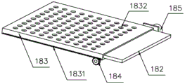
FIG. 5 is a schematic view showing the structure of a filtering mechanism in a wastewater treatment plant for construction according to the present invention;
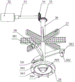
FIG. 6 is a schematic view showing the internal structure of a stirring tank in the wastewater treatment apparatus for construction according to the present invention;
in the figure: 1. a silt treatment mechanism; 10. a housing case; 11. a splash guard; 12. a water inlet pipeline; 13. a barrier cleaning mechanism; 131. a spoiler; 1311. a convex cone; 1312. a diversion trench; 1313. rotating the connecting shaft; 132. an oil cylinder II; 14. a filter plate I; 15. a flow-impeding baffle; 16. a baffle; 17. an oil cylinder I; 18. a filtering mechanism; 181. a guide rail; 182. a filter plate II; 183. a support frame; 1831. a rack; 1832. a through hole; 184. a gear I; 185. a motor I; 2. a water flow channel; 21. a water pump; 3. a flocculation stirring mechanism; 30. a medicine adding port; 31. a stirring box; 32. a motor II; 33. a drive shaft; 34. a bevel gear I; 35. a bevel gear II; 36. a rotating shaft; 37. stirring fan blades I; 371. a feed through hole; 38. stirring fan blades II; 381. a spoiler; 382. a ball bearing; 383. connecting a base; 39. rotating the base; 391. a stirring plate; 392. an internal tooth chassis; 393. an auxiliary support shaft; 394. a connecting groove; 395. a gear II; 4. a pollution discharge purification mechanism; 40. a cache box; 41. a spiral guide shaft; 42. a settling plate; 43. an oil cylinder III; 44. a support frame; 45. pressing a plate; 46. a buffer plate; 47. a drainage connecting pipe; 48. a valve I; 49. a motor III; 5. a communicating pipeline; 51. and a valve II.
Detailed Description
For the convenience of understanding of those skilled in the art, the technical solution of the present invention will be further described in detail with reference to fig. 1 to 6.
A wastewater treatment device for building construction comprises a sediment treatment mechanism 1, a water flow channel 2, a water pump 21, a flocculation stirring mechanism 3, a sewage purification mechanism 4, a communicating pipeline 5 and a valve II 51, wherein the water flow channel 2 is arranged on one side of the sediment treatment mechanism 1, the water pump 21 is arranged on one side of the water flow channel 2, the flocculation stirring mechanism 3 is arranged on the other side of the water flow channel 2, the sewage purification mechanism 4 is arranged on one side of the flocculation stirring mechanism 3, the communicating pipeline 5 is arranged between the flocculation stirring mechanism 3 and the sewage purification mechanism 4, and the valve II 51 is arranged on one side of the communicating pipeline 5;
in to the construction wastewater treatment process, clear up the silt that contains in the aquatic through silt processing mechanism 1, let in flocculation rabbling mechanism 3 through rivers passageway 2 with waste water through water pump 21 again, make aquatic impurity and flocculating agent fully combine through the stirring behind the adding the flocculating agent in flocculation rabbling mechanism 3, open behind valve II 51 and get into blowdown purification mechanism 4 through communicating pipe 5 and handle.
The silt treatment mechanism 1 comprises a shell box 10, a splash-proof shield 11, a water inlet pipeline 12, a blocking and cleaning mechanism 13, a filter plate I14, a flow blocking partition plate 15, a guide plate 16, an oil cylinder I17 and a filtering mechanism 18, wherein the splash-proof shield 11 is arranged on one side of the shell box 10, the water inlet pipeline 12 is arranged on one side of the splash-proof shield 11, the blocking and cleaning mechanism 13 is arranged on one side of the water inlet pipeline 12, the filter plate I14 is arranged on one side of the blocking and cleaning mechanism 13, the guide plate 16 is arranged on one side of the filter plate I14, the flow blocking partition plate 15 is arranged on one side of the guide plate 16, the oil cylinder I17 is arranged on one side of the flow blocking partition plate 15, the filtering mechanism 18 is arranged on the other side of the filter plate I14, the splash-proof shield 11 is fixedly connected with the shell box 10, the water inlet pipeline 12 is fixed inside the splash-proof shield 11, the flow blocking partition plate 15, the filter plate I14 and the filtering mechanism 18 are all fixed inside the shell box 10, and the shell box 10 is provided with maintenance ports at the positions of the guide plate 16 and the filtering mechanism 18;
when the construction wastewater treatment device is used, construction wastewater is introduced into the shell box 10 through the water inlet pipeline 12, impurities contained in the wastewater are firstly blocked and cleaned through the blocking and cleaning mechanism 13, the construction wastewater flows through the filter plate I14, the filter plate I14 has a certain inclination angle, water flow can quickly pass through the filter plate I14, the filter plate I14 can be prevented from being blocked, silt continuously gathers towards an access hole on the filter plate I14, power is provided through the oil cylinder I17 after a certain amount of silt is reached, the flow blocking partition plate 15 is driven to move upwards, the silt quickly flows out under the action of the guide plate 16, and the wastewater is further filtered and purified through the filter mechanism 18 through the filter plate I14;
the flocculation stirring mechanism 3 comprises a medicine adding port 30, a stirring box 31, a motor II 32, a transmission shaft 33, a bevel gear I34, a bevel gear II 35, a rotating shaft 36, stirring blades I37, a material passing hole 371, stirring blades II 38 and a rotating base 39, wherein the medicine adding port 30 is arranged on one side of the stirring box 31, the motor II 32 is arranged at the top of the stirring box 31, the transmission shaft 33 is arranged on one side of the motor II 32, the bevel gear I34 is arranged on one side of the transmission shaft 33, the bevel gear II 35 is arranged on one side of the bevel gear I34, the rotating shaft 36 is arranged on one side of the bevel gear II 35, the stirring blades I37 are arranged on one side of the rotating shaft 36, a plurality of material passing holes 371 are formed in the stirring blades I37, the stirring blades II 38 are arranged on the other side of the stirring blades I37, and the rotating base 39 is arranged on one side of the stirring blades II 38;
The blocking cleaning mechanism 13 comprises a spoiler 131 and an oil cylinder II 132, wherein the oil cylinder II 132 is arranged on one side of the spoiler 131, the oil cylinder II 132 is connected to the outer side wall of the outer case 10, the spoiler 131 comprises a convex cone 1311, a diversion groove 1312 and a rotary connecting shaft 1313, the convex cone 1311 is arranged on the surface of the spoiler 131, the diversion groove 1312 is arranged inside the spoiler 131, and the rotary connecting shaft 1313 is arranged between the spoiler 131 and the outer case 10;
the filter mechanism 18 comprises a guide rail 181, a filter plate II 182, a supporting frame 183, a rack 1831, through holes 1832, a gear I184 and a motor I185, wherein the gear I184 is arranged on one side of the motor I185, the supporting frame 183 is arranged on one side of the gear I184, the filter plate II 182 is arranged in the supporting frame 183, a plurality of through holes 1832 are arranged on the surface of the supporting frame 183, the rack 1831 is arranged at two ends of the supporting frame 183, the guide rail 181 is arranged on the other side of the supporting frame 183, the guide rail 181 is fixed on the inner wall of the casing 10 and is in contact with the supporting frame 183, the rack 1831 is fixed on the side wall of the supporting frame 183 and is meshed with the gear I184, water flows into the filter plate II 182 through the through holes 1832 on the supporting frame 183 and is filtered through the rack II 182, when the filter plate II 182 needs to be replaced, the power is provided through the motor I185 to drive the gear I184 to rotate, the gear I184 leads the supporting frame 183 out along the guide rail 181, and can directly replace the filter plate II 182 in the supporting frame 183.
Stirring fan blade II 38 includes spoiler 381, ball 382, connects base 383, it sets up in stirring fan blade II 38 outer tip to connect base 383, it is equipped with ball 382 to connect base 383 inside, ball 382 one side is equipped with spoiler 381, it fixes on stirring fan blade II 38 to connect base 383, ball 382 places inside connecting base 383, spoiler 381 is connected with ball 382, when stirring fan blade II 38 rotates, spoiler 381 is strikeed by the rivers and is rotated, disturb disconnected rivers direction of rotation, prevent that rivers from constantly rotating to same direction, the inside relative stillness that takes place of rivers, it is not abundant enough to make the stirring, keep the stability of equipment simultaneously.
The rotating base 39 comprises a stirring plate 391, an internal tooth chassis 392, an auxiliary support shaft 393, a connecting groove 394 and a gear II 395, wherein the internal tooth chassis 392 is arranged on one side of the gear II 395, the connecting groove 394 is arranged inside the internal tooth chassis 392, the auxiliary support shaft 393 is arranged inside the connecting groove 394, the stirring plate 391 is arranged on the internal tooth chassis 392, the gear II 395 is fixedly connected with the rotating shaft 36, the gear II 395 is meshed with the internal tooth chassis 392, one end of the auxiliary support shaft 393 is fixed at the bottom of the stirring box, the other end of the auxiliary support shaft 393 is connected inside the connecting groove 394, the stirring plate 391 is fixed on the internal tooth chassis 392, the rotating shaft 36 drives the gear II 395 to rotate, the gear II 395 drives the internal tooth chassis 392 to rotate under the action of the auxiliary support shaft 393, and the internal tooth chassis 392 drives the stirring plate 391 to stir.
The pollution discharge purification mechanism 4 comprises a buffer box 40, a spiral guide shaft 41, a settling plate 42, an oil cylinder III 43, a support frame 44, a pressing plate 45, a buffer plate 46, a drainage connecting pipe 47, a valve I48 and a motor III 49, wherein one side of the buffer box 40 is provided with the motor III 49, one side of the motor III 49 is provided with the spiral guide shaft 41, one side of the spiral guide shaft 41 is provided with the settling plate 42, one side of the settling plate 42 is provided with the pressing plate 45, one side of the pressing plate 45 is provided with the oil cylinder III 43, one side of the oil cylinder III 43 is provided with the support frame 44, the other side of the settling plate 42 is provided with the buffer plate 46, the drainage connecting pipe 47 is arranged on the side wall of the buffer box 40, one side of the drainage connecting pipe 47 is provided with the valve I48, water flows into the buffer box 40 through a communicating pipe 5 and is ejected out through the oil cylinder 43 to drive the pressing plate 45 to move downwards continuously, so that the water flows through the pressing plate 45 to flow through the upper part of the settling plate 42 and flows into the other side of the buffer box 40 under the action of the buffer plate 46, and after coagulated flocs are extruded, the flocs are driven by the motor 49 to lead the spiral guide shaft 41 to lead out the flocs.
The foregoing is merely exemplary and illustrative of the present invention and various modifications, additions and substitutions may be made by those skilled in the art to the specific embodiments described without departing from the scope of the present invention as defined in the accompanying claims.
Claims (4)
1. A waste water treatment device for building construction comprises a sediment treatment mechanism, a water flow channel, a water pump, a flocculation stirring mechanism, a pollution discharge purification mechanism, a communicating pipeline and a valve II, and is characterized in that the water flow channel is arranged on one side of the sediment treatment mechanism, the water pump is arranged on one side of the water flow channel, the flocculation stirring mechanism is arranged on the other side of the water flow channel, the pollution discharge purification mechanism is arranged on one side of the flocculation stirring mechanism, the communicating pipeline is arranged between the flocculation stirring mechanism and the pollution discharge purification mechanism, and the valve II is arranged on one side of the communicating pipeline;
the silt treatment mechanism comprises a shell box, an anti-splash guard, a water inlet pipeline, a blocking and cleaning mechanism, a filter plate I, a flow-blocking partition plate, a guide plate, an oil cylinder I and a filtering mechanism, wherein the anti-splash guard is arranged on one side of the shell box, the water inlet pipeline is arranged on one side of the anti-splash guard, the blocking and cleaning mechanism is arranged on one side of the water inlet pipeline, the filter plate I is arranged on one side of the blocking and cleaning mechanism, the guide plate is arranged on one side of the filter plate I, the flow-blocking partition plate is arranged on one side of the guide plate, the oil cylinder I is arranged on one side of the flow-blocking partition plate, the filtering mechanism is arranged on the other side of the filter plate I, the anti-splash guard is fixedly connected with the shell box, the water inlet pipeline is fixed in the anti-splash guard, the flow-blocking partition plate, the filter plate I and the filtering mechanism are all fixed in the shell box, and the shell box is provided with an inspection hole at the positions of the guide plate and the filtering mechanism;
the flocculation stirring mechanism comprises a dosing port, a stirring box, a motor II, a transmission shaft, a bevel gear I, a bevel gear II, a rotating shaft, a stirring fan blade I, a material passing hole, a stirring fan blade II and a rotating base, wherein the dosing port is formed in one side of the stirring box, the motor II is arranged at the top of the stirring box, the transmission shaft is arranged on one side of the motor II, the bevel gear I is arranged on one side of the transmission shaft, the bevel gear II is arranged on one side of the bevel gear I, the rotating shaft is arranged on one side of the bevel gear II, the stirring fan blade I is arranged on one side of the rotating shaft, a plurality of material passing holes are formed in the stirring fan blade I, the stirring fan blade II is arranged on the other side of the stirring fan blade I, and the rotating base is arranged on one side of the stirring fan blade II;
the motor II is connected with the transmission shaft through a coupler, the bevel gear I is connected to the transmission shaft through a key, the bevel gear I and the bevel gear II are meshed with each other, the bevel gear II is connected to the rotating shaft through a key, and the stirring fan blades I, the stirring fan blades II and the rotating base are respectively fixed to the upper portion, the middle portion and the lower portion of the rotating shaft;
the blocking and cleaning mechanism comprises a spoiler and an oil cylinder II, wherein the oil cylinder II is arranged on one side of the spoiler, the oil cylinder II is connected to the outer side wall of the outer shell, the spoiler comprises a convex cone, a diversion groove and a rotary connecting shaft, the convex cone is arranged on the surface of the spoiler, the diversion groove is arranged inside the spoiler, and the rotary connecting shaft is arranged between the spoiler and the outer shell;
stirring fan blade II includes spoiler, ball, connection base, it sets up in II outer tip of stirring fan blade to connect the base, connect the inside ball that is equipped with of base, ball one side is equipped with the spoiler, connects the base and fixes on stirring fan blade II, and the ball is placed inside connecting the base, and the spoiler is connected with the ball.
2. The wastewater treatment device for building construction according to claim 1, wherein the filtering mechanism comprises a guide rail, a filter plate II, a support frame, a rack, through holes, a gear I and a motor I, the gear I is arranged on one side of the motor I, the support frame is arranged on one side of the gear I, the filter plate II is arranged in the support frame, the surface of the support frame is provided with a plurality of through holes, the rack is arranged at two ends of the support frame, the guide rail is arranged on the other side of the support frame, the guide rail is fixed on the inner wall of the casing and is in contact with the support frame, and the rack is fixed on the side wall of the support frame and is meshed with the gear I.
3. The wastewater treatment device for building construction according to claim 1, wherein the rotating base comprises a stirring plate, an internal tooth chassis, an auxiliary support shaft, a connecting groove and a gear II, the internal tooth chassis is arranged on one side of the gear II, the connecting groove is arranged inside the internal tooth chassis, the auxiliary support shaft is arranged inside the connecting groove, the stirring plate is arranged on the internal tooth chassis, the gear II is fixedly connected with the rotating shaft, the gear II is meshed with the internal tooth chassis, one end of the auxiliary support shaft is fixed at the bottom of the stirring box, the other end of the auxiliary support shaft is connected inside the connecting groove, and the stirring plate is fixed on the internal tooth chassis.
4. The wastewater treatment device for building construction according to claim 1, wherein the pollution discharge purification mechanism comprises a buffer tank, a spiral guide shaft, a settling plate, an oil cylinder III, a support frame, a pressing plate, a buffering plate, a drainage connecting pipe, a valve I and a motor III, wherein the motor III is arranged on one side of the buffer tank, the spiral guide shaft is arranged on one side of the motor III, the settling plate is arranged on one side of the spiral guide shaft, the pressing plate is arranged on one side of the settling plate, the oil cylinder III is arranged on one side of the pressing plate, the support frame is arranged on one side of the oil cylinder III, the buffering plate is arranged on the other side of the settling plate, the drainage connecting pipe is arranged on the side wall of the buffer tank, the valve I is arranged on one side of the drainage connecting pipe, and water flows into the buffer tank through a communication pipeline.
Priority Applications (1)
| Application Number | Priority Date | Filing Date | Title |
|---|---|---|---|
| CN202110655399.7A CN113429015B (en) | 2021-06-11 | 2021-06-11 | A effluent treatment plant for construction |
Applications Claiming Priority (1)
| Application Number | Priority Date | Filing Date | Title |
|---|---|---|---|
| CN202110655399.7A CN113429015B (en) | 2021-06-11 | 2021-06-11 | A effluent treatment plant for construction |
Publications (2)
| Publication Number | Publication Date |
|---|---|
| CN113429015A CN113429015A (en) | 2021-09-24 |
| CN113429015B true CN113429015B (en) | 2023-04-07 |
Family
ID=77755775
Family Applications (1)
| Application Number | Title | Priority Date | Filing Date |
|---|---|---|---|
| CN202110655399.7A Active CN113429015B (en) | 2021-06-11 | 2021-06-11 | A effluent treatment plant for construction |
Country Status (1)
| Country | Link |
|---|---|
| CN (1) | CN113429015B (en) |
Families Citing this family (2)
| Publication number | Priority date | Publication date | Assignee | Title |
|---|---|---|---|---|
| CN114149162B (en) * | 2021-12-22 | 2023-10-20 | 江苏鑫环球建设工程有限公司 | Silt treatment device for hydraulic engineering |
| CN116173614B (en) * | 2023-04-03 | 2023-09-01 | 临沂市环境保护科学研究所有限公司 | A prevent blockking up filtration treatment device for waste water treatment |
Citations (4)
| Publication number | Priority date | Publication date | Assignee | Title |
|---|---|---|---|---|
| US4612123A (en) * | 1983-01-25 | 1986-09-16 | Maschinenfabrik Andritz Actiengesellschaft | Regulating apparatus for dewatering machines |
| CN101475239A (en) * | 2009-01-12 | 2009-07-08 | 上海环境保护有限公司 | Automatic feeding apparatus preparing pool for powdered activated charcoal |
| CN107740489A (en) * | 2017-12-10 | 2018-02-27 | 王浩浩 | A kind of anti-blocking cistern of hydraulic engineering |
| CN109300624A (en) * | 2018-09-05 | 2019-02-01 | 佛山市源春月贸易有限公司 | A kind of wire and cable cladding mechanism |
Family Cites Families (6)
| Publication number | Priority date | Publication date | Assignee | Title |
|---|---|---|---|---|
| DE2420744C3 (en) * | 1974-04-29 | 1980-02-28 | Ishigaki Kiko Co., Ltd., Tokio | Device for purifying waste water |
| CN206082326U (en) * | 2016-08-25 | 2017-04-12 | 盛浩达 | Movable coating stirrer constructs |
| CN106512514A (en) * | 2016-12-10 | 2017-03-22 | 芜湖航达网业有限公司 | Full-automatic anti-blocking wastewater filtering net |
| CN207957987U (en) * | 2018-01-24 | 2018-10-12 | 宿迁市建设工程监理咨询中心有限公司 | A kind of recycle device of building waste water |
| CN111018179A (en) * | 2019-12-13 | 2020-04-17 | 刘勇英 | Energy-saving water treatment environment-friendly equipment and treatment process |
| CN212222673U (en) * | 2020-05-26 | 2020-12-25 | 青岛盈鑫建设集团有限公司 | Waste water recycling apparatus for building engineering |
-
2021
- 2021-06-11 CN CN202110655399.7A patent/CN113429015B/en active Active
Patent Citations (4)
| Publication number | Priority date | Publication date | Assignee | Title |
|---|---|---|---|---|
| US4612123A (en) * | 1983-01-25 | 1986-09-16 | Maschinenfabrik Andritz Actiengesellschaft | Regulating apparatus for dewatering machines |
| CN101475239A (en) * | 2009-01-12 | 2009-07-08 | 上海环境保护有限公司 | Automatic feeding apparatus preparing pool for powdered activated charcoal |
| CN107740489A (en) * | 2017-12-10 | 2018-02-27 | 王浩浩 | A kind of anti-blocking cistern of hydraulic engineering |
| CN109300624A (en) * | 2018-09-05 | 2019-02-01 | 佛山市源春月贸易有限公司 | A kind of wire and cable cladding mechanism |
Also Published As
| Publication number | Publication date |
|---|---|
| CN113429015A (en) | 2021-09-24 |
Similar Documents
| Publication | Publication Date | Title |
|---|---|---|
| CN113429015B (en) | A effluent treatment plant for construction | |
| CN111960519A (en) | Flocculation decontamination formula industrial sewage treatment device with self-cleaning function | |
| CN210915467U (en) | Municipal administration sewage recovery processing apparatus | |
| CN220201698U (en) | High-efficient air supporting solid-liquid separation device | |
| CN210885400U (en) | Flotation device for sewage treatment | |
| CN207259197U (en) | A kind of air-flotation type wastewater efficient processing unit | |
| CN206346246U (en) | A kind of environment-protective desilting floats clearly integrated apparatus | |
| CN215387859U (en) | Sand and stone filtering device of irrigation system | |
| KR100753874B1 (en) | Flocculator having a scum discharging part | |
| CN212687792U (en) | Sewage treatment device for water environment treatment | |
| CN214130690U (en) | Filter separation system of lower dredging | |
| CN209957549U (en) | Oil field sewage filter equipment | |
| CN213060486U (en) | Improved mine water underground impurity filtering combination device | |
| CN213537545U (en) | Rural sewage on-line control operating equipment convenient to use | |
| CN212269720U (en) | Advanced oxidation treatment device for landfill leachate concentrated solution | |
| CN210905135U (en) | Novel industrial sewage treatment is with filtering device | |
| CN113816583A (en) | Device and method for treating sludge water of tap water plant | |
| CN212356840U (en) | Immersion type ultrafiltration membrane short-flow water treatment device adopting inclined pipe | |
| CN216946549U (en) | High-concentration wastewater recycling device of mixing plant | |
| CN217202436U (en) | Medical sewage treatment equipment based on MBBR technology | |
| CN215627276U (en) | A air supporting deposits all-in-one for sewage treatment | |
| CN219709331U (en) | Sedimentation tank of sewage treatment | |
| CN219630817U (en) | Desilting device for desilting pond | |
| CN220723890U (en) | Coagulation device for water pollution chemical treatment | |
| CN218786545U (en) | Sewage treatment sand settling device |
Legal Events
| Date | Code | Title | Description |
|---|---|---|---|
| PB01 | Publication | ||
| PB01 | Publication | ||
| SE01 | Entry into force of request for substantive examination | ||
| SE01 | Entry into force of request for substantive examination | ||
| TA01 | Transfer of patent application right |
Effective date of registration: 20230118 Address after: 200000 room 112b, No. 1121, Zhongshan North 2nd Road, Yangpu District, Shanghai Applicant after: Shanghai Zhitong Construction Engineering Technology Co.,Ltd. Address before: 276017 room 517, block a, innovation building, shuangyueyuan Road, high tech Industrial Development Zone, Linyi City, Shandong Province Applicant before: Zhongzhi machinery (Linyi) Co.,Ltd. |
|
| TA01 | Transfer of patent application right | ||
| GR01 | Patent grant | ||
| GR01 | Patent grant |