CN113413702B - Waste gas purification process for recycling lead-acid storage battery - Google Patents
Waste gas purification process for recycling lead-acid storage battery Download PDFInfo
- Publication number
- CN113413702B CN113413702B CN202110717733.7A CN202110717733A CN113413702B CN 113413702 B CN113413702 B CN 113413702B CN 202110717733 A CN202110717733 A CN 202110717733A CN 113413702 B CN113413702 B CN 113413702B
- Authority
- CN
- China
- Prior art keywords
- gas
- box
- pipe
- waste gas
- exhaust
- Prior art date
- Legal status (The legal status is an assumption and is not a legal conclusion. Google has not performed a legal analysis and makes no representation as to the accuracy of the status listed.)
- Active
Links
- 238000000746 purification Methods 0.000 title claims abstract description 112
- 239000002912 waste gas Substances 0.000 title claims abstract description 112
- 239000002253 acid Substances 0.000 title claims abstract description 58
- 238000004064 recycling Methods 0.000 title claims abstract description 13
- 239000007789 gas Substances 0.000 claims abstract description 175
- 239000007788 liquid Substances 0.000 claims abstract description 112
- 239000000428 dust Substances 0.000 claims abstract description 101
- 238000001914 filtration Methods 0.000 claims abstract description 60
- 239000004744 fabric Substances 0.000 claims abstract description 38
- 238000011084 recovery Methods 0.000 claims abstract description 11
- 238000005507 spraying Methods 0.000 claims abstract description 11
- 230000002378 acidificating effect Effects 0.000 claims abstract description 9
- 239000007921 spray Substances 0.000 claims abstract description 8
- 239000002245 particle Substances 0.000 claims abstract description 7
- 238000001514 detection method Methods 0.000 claims description 61
- 229910052751 metal Inorganic materials 0.000 claims description 32
- 239000002184 metal Substances 0.000 claims description 32
- 238000004140 cleaning Methods 0.000 claims description 27
- 230000005540 biological transmission Effects 0.000 claims description 23
- 230000000694 effects Effects 0.000 claims description 14
- 230000007246 mechanism Effects 0.000 claims description 12
- 230000002093 peripheral effect Effects 0.000 claims description 11
- 230000009471 action Effects 0.000 claims description 8
- 238000004891 communication Methods 0.000 claims description 6
- 238000000034 method Methods 0.000 claims description 4
- 230000008569 process Effects 0.000 claims description 4
- 238000012545 processing Methods 0.000 claims description 3
- 238000001802 infusion Methods 0.000 claims description 2
- 230000000903 blocking effect Effects 0.000 claims 2
- RAHZWNYVWXNFOC-UHFFFAOYSA-N Sulphur dioxide Chemical compound O=S=O RAHZWNYVWXNFOC-UHFFFAOYSA-N 0.000 description 6
- 238000010586 diagram Methods 0.000 description 5
- 239000010419 fine particle Substances 0.000 description 4
- 230000033001 locomotion Effects 0.000 description 4
- 239000000463 material Substances 0.000 description 4
- XLYOFNOQVPJJNP-UHFFFAOYSA-N water Substances O XLYOFNOQVPJJNP-UHFFFAOYSA-N 0.000 description 4
- 241001075561 Fioria Species 0.000 description 3
- 238000003780 insertion Methods 0.000 description 3
- 230000037431 insertion Effects 0.000 description 3
- QAOWNCQODCNURD-UHFFFAOYSA-N Sulfuric acid Chemical compound OS(O)(=O)=O QAOWNCQODCNURD-UHFFFAOYSA-N 0.000 description 2
- 239000003513 alkali Substances 0.000 description 2
- 239000007864 aqueous solution Substances 0.000 description 2
- 230000001174 ascending effect Effects 0.000 description 2
- 230000009286 beneficial effect Effects 0.000 description 2
- YADSGOSSYOOKMP-UHFFFAOYSA-N dioxolead Chemical compound O=[Pb]=O YADSGOSSYOOKMP-UHFFFAOYSA-N 0.000 description 2
- 239000003792 electrolyte Substances 0.000 description 2
- 238000012986 modification Methods 0.000 description 2
- 230000004048 modification Effects 0.000 description 2
- 239000000243 solution Substances 0.000 description 2
- 238000010408 sweeping Methods 0.000 description 2
- VYZAMTAEIAYCRO-UHFFFAOYSA-N Chromium Chemical compound [Cr] VYZAMTAEIAYCRO-UHFFFAOYSA-N 0.000 description 1
- RWSOTUBLDIXVET-UHFFFAOYSA-N Dihydrogen sulfide Chemical compound S RWSOTUBLDIXVET-UHFFFAOYSA-N 0.000 description 1
- 229920001875 Ebonite Polymers 0.000 description 1
- 238000007792 addition Methods 0.000 description 1
- 239000002585 base Substances 0.000 description 1
- 230000001680 brushing effect Effects 0.000 description 1
- 229910052804 chromium Inorganic materials 0.000 description 1
- 239000011651 chromium Substances 0.000 description 1
- 230000006835 compression Effects 0.000 description 1
- 238000007906 compression Methods 0.000 description 1
- 230000007547 defect Effects 0.000 description 1
- 229920006351 engineering plastic Polymers 0.000 description 1
- 239000011152 fibreglass Substances 0.000 description 1
- 239000012530 fluid Substances 0.000 description 1
- 229910001385 heavy metal Inorganic materials 0.000 description 1
- 229910000037 hydrogen sulfide Inorganic materials 0.000 description 1
- 239000013618 particulate matter Substances 0.000 description 1
- 239000004033 plastic Substances 0.000 description 1
- 229920003023 plastic Polymers 0.000 description 1
- 239000011148 porous material Substances 0.000 description 1
- 239000000843 powder Substances 0.000 description 1
- 239000002994 raw material Substances 0.000 description 1
- 238000006467 substitution reaction Methods 0.000 description 1
- 238000012360 testing method Methods 0.000 description 1
- 231100000331 toxic Toxicity 0.000 description 1
- 230000002588 toxic effect Effects 0.000 description 1
- 239000002341 toxic gas Substances 0.000 description 1
Images


Classifications
-
- B—PERFORMING OPERATIONS; TRANSPORTING
- B01—PHYSICAL OR CHEMICAL PROCESSES OR APPARATUS IN GENERAL
- B01D—SEPARATION
- B01D46/00—Filters or filtering processes specially modified for separating dispersed particles from gases or vapours
- B01D46/10—Particle separators, e.g. dust precipitators, using filter plates, sheets or pads having plane surfaces
-
- B—PERFORMING OPERATIONS; TRANSPORTING
- B01—PHYSICAL OR CHEMICAL PROCESSES OR APPARATUS IN GENERAL
- B01D—SEPARATION
- B01D53/00—Separation of gases or vapours; Recovering vapours of volatile solvents from gases; Chemical or biological purification of waste gases, e.g. engine exhaust gases, smoke, fumes, flue gases, aerosols
- B01D53/30—Controlling by gas-analysis apparatus
-
- B—PERFORMING OPERATIONS; TRANSPORTING
- B01—PHYSICAL OR CHEMICAL PROCESSES OR APPARATUS IN GENERAL
- B01D—SEPARATION
- B01D53/00—Separation of gases or vapours; Recovering vapours of volatile solvents from gases; Chemical or biological purification of waste gases, e.g. engine exhaust gases, smoke, fumes, flue gases, aerosols
- B01D53/34—Chemical or biological purification of waste gases
- B01D53/38—Removing components of undefined structure
- B01D53/40—Acidic components
-
- B—PERFORMING OPERATIONS; TRANSPORTING
- B01—PHYSICAL OR CHEMICAL PROCESSES OR APPARATUS IN GENERAL
- B01D—SEPARATION
- B01D53/00—Separation of gases or vapours; Recovering vapours of volatile solvents from gases; Chemical or biological purification of waste gases, e.g. engine exhaust gases, smoke, fumes, flue gases, aerosols
- B01D53/34—Chemical or biological purification of waste gases
- B01D53/74—General processes for purification of waste gases; Apparatus or devices specially adapted therefor
- B01D53/77—Liquid phase processes
- B01D53/78—Liquid phase processes with gas-liquid contact
-
- B—PERFORMING OPERATIONS; TRANSPORTING
- B01—PHYSICAL OR CHEMICAL PROCESSES OR APPARATUS IN GENERAL
- B01D—SEPARATION
- B01D2258/00—Sources of waste gases
- B01D2258/02—Other waste gases
-
- Y—GENERAL TAGGING OF NEW TECHNOLOGICAL DEVELOPMENTS; GENERAL TAGGING OF CROSS-SECTIONAL TECHNOLOGIES SPANNING OVER SEVERAL SECTIONS OF THE IPC; TECHNICAL SUBJECTS COVERED BY FORMER USPC CROSS-REFERENCE ART COLLECTIONS [XRACs] AND DIGESTS
- Y02—TECHNOLOGIES OR APPLICATIONS FOR MITIGATION OR ADAPTATION AGAINST CLIMATE CHANGE
- Y02W—CLIMATE CHANGE MITIGATION TECHNOLOGIES RELATED TO WASTEWATER TREATMENT OR WASTE MANAGEMENT
- Y02W30/00—Technologies for solid waste management
- Y02W30/50—Reuse, recycling or recovery technologies
- Y02W30/84—Recycling of batteries or fuel cells
Landscapes
- Chemical & Material Sciences (AREA)
- Engineering & Computer Science (AREA)
- Chemical Kinetics & Catalysis (AREA)
- Analytical Chemistry (AREA)
- Environmental & Geological Engineering (AREA)
- General Chemical & Material Sciences (AREA)
- Oil, Petroleum & Natural Gas (AREA)
- Health & Medical Sciences (AREA)
- Biomedical Technology (AREA)
- Treating Waste Gases (AREA)
Abstract
The invention belongs to the technical field of lead-acid battery recovery, and aims to solve the problems that the waste gas for lead-acid battery recovery is simply filtered by a filter screen at present to filter out particle dust in the waste gas, acid gas in the waste gas cannot be effectively removed, and acidic harmful gas in the waste gas can cause serious pollution to the environment, in particular to a waste gas purification process for lead-acid battery recovery, which comprises the following steps: dust filtration treatment; filtering and deacidifying treatment: filtering and deacidifying the waste gas by using filter cloth attached with the acid gas treatment liquid; deacidifying and purifying treatment: the fixed pipe sprays the treatment liquid through the liquid spraying holes on the inner circumferential surface, so that the waste gas is fully contacted with the treatment liquid; the invention not only can filter dust of the waste gas for recycling the lead-acid storage battery to filter lead-containing dust, but also can effectively absorb acid harmful gas in the waste gas, thereby obviously reducing the pollution to the environment.
Description
Technical Field
The invention relates to the technical field of lead-acid storage battery recovery, in particular to a waste gas purification process for lead-acid storage battery recovery.
Background
The storage batteries using acidic aqueous solution as electrolyte are commonly referred to as acid storage batteries, wherein the most typical storage battery is a lead-acid storage battery, and the acid storage battery has the main advantages of higher working voltage, wide use temperature, good high-low rate discharge performance, rich raw material sources and low price, and has the defects of lower energy density and larger volume and weight; the lead-acid storage battery comprises a positive electrode of lead dioxide, a negative electrode of spongy lead, an electrolyte of sulfuric acid aqueous solution, a microporous rubber separator, a microporous plastic separator or other materials used by the separators according to different types of lead storage batteries, and a battery shell made of hard rubber, engineering plastics, glass fiber reinforced plastics and other materials;
when the lead-acid storage battery is recycled, a large amount of battery powder dust and toxic gas can be generated, the dust contains a large amount of toxic heavy metals such as lead, chromium and the like, the gas contains harmful gases such as hydrogen sulfide, sulfur dioxide and the like, when the waste gas is treated by the conventional treatment process, the waste gas is generally simply filtered by a filter screen to filter out particle dust in the waste gas, the acid gas in the waste gas cannot be effectively removed, and the acid harmful gas in the waste gas can cause serious pollution to the environment and needs to be improved;
in view of the above technical drawbacks, a solution is proposed.
Disclosure of Invention
The invention aims to provide a waste gas purification process for recycling a lead-acid storage battery, which is characterized in that waste gas is subjected to dust filtration treatment through a metal dust filtration net to filter lead-containing dust in the waste gas, the metal dust filtration net is repeatedly brushed and swept through a sweeping brush to realize automatic cleaning of the metal dust filtration net, fine particles and acid gas in the waste gas are preliminarily removed through contact between filter cloth attached with acid gas treatment liquid and the waste gas, a fixed pipe uniformly sprays the treatment liquid through liquid spraying holes in the inner peripheral surface, the waste gas is fully contacted with the treatment liquid to thoroughly clean the acid gas in the waste gas, a gas detection sensor detects the gas in a detection box to judge whether the waste gas treatment result reaches the standard, the problem that the waste gas for recycling the lead-acid storage battery is simply filtered through a filter screen to filter the particle dust in the waste gas at present and the acid gas in the waste gas cannot be effectively cleaned is solved, the acidic harmful gas in the waste gas can cause serious pollution to the environment.
In order to achieve the purpose, the invention provides the following technical scheme:
a waste gas purification process for recycling a lead-acid storage battery comprises the following steps:
s1, dust filtration treatment: collecting waste gas generated in the recovery process of the lead-acid storage battery, introducing the waste gas into a dust removal box through a waste gas input pipe, filtering the waste gas through a metal dust filtering net, and enabling filtered lead-containing dust to fall to the inner wall of the bottom of the dust removal box;
in the dust filtering process, the trapezoidal exhaust box sprays exhaust gas to the rotating blades through the flat blast holes, the rotating blades drive the movable shaft to rotate under the action of wind power, the pull rod pulls the movable rod to transversely reciprocate through the rotating rod, the sliding block transversely reciprocates along the guide rod under the push-pull action of the movable rod, the cleaning brush repeatedly brushes the metal dust filtering net, and particulate matters blocked in the filtering holes are brushed down;
s2, filtering and deacidifying: the waste gas after dust filtration treatment enters a primary purification tank through a first gas transmission pipe, and the waste gas is filtered and deacidified through filter cloth attached with acid gas treatment liquid;
the rotating shaft drives the connecting plate to rotate, the filter cloth rotates along with the connecting plate, and when the filter cloth rotates to the lower part of the interior of the primary purification tank, the acidic gas treatment liquid in the primary purification tank soaks and cleans the filter cloth, so that the filter cloth is always kept in a wet state;
s3, deacidifying and purifying: waste gas subjected to preliminary filtering and deacidification treatment enters the purification cavity through the second gas conveying pipe, the waste gas in the purification cavity upwards enters each fixed pipe, the acid gas treatment liquid is conveyed into the hollow circular ring by the liquid conveying pipe, the treatment liquid is conveyed into the liquid collecting cavity in each fixed pipe by the hollow circular ring through each connecting pipe, and the treatment liquid is sprayed out of the fixed pipes through the liquid spraying holes in the inner peripheral surface, so that the waste gas is fully contacted with the treatment liquid to achieve complete deacidification;
s4, gas detection processing: the output shaft drives the exhaust fan blades to rotate, the air in the purification cavity is conveyed into the exhaust cavity through the exhaust effect of the exhaust fan blades, and the fourth gas pipe conveys the air into the detection box; the gas detection sensor detects gas in the detection box, and the fifth gas transmission pipe guides the gas in the detection box out;
when the detection result of the processed gas passing through the gas detection sensor reaches the standard, the control valve on the exhaust pipe is opened to discharge the gas, and when the detection result of the processed gas passing through the gas detection sensor does not reach the standard, the control valve on the gas return pipe is opened and conveys the gas to the waste gas input pipe, and then the gas is purified again.
Further, a fixed plate is fixedly installed on the dust removal box through a bolt, and a metal dust filter screen is arranged in the middle of the fixed plate; the primary purification tank is fixedly arranged at the top of the dust removal box through bolts, the secondary purification box is fixedly arranged at the top of the dust removal box through bolts, a purification cavity and an air exhaust cavity are formed in the secondary purification box, and the air exhaust cavity is positioned above the purification cavity; the first gas pipe is communicated with the dust removal box and the primary purification tank, the second gas pipe is communicated with the primary purification tank and the purification cavity, the first gas pipe and the second gas pipe are positioned on two sides of the primary purification tank, and the communication part of the first gas pipe and the dust removal box is positioned above the metal dust filter screen;
the detection box is fixedly arranged on the secondary purification box through bolts, and a gas detection sensor is fixedly arranged in the detection box through bolts; a fourth gas pipe communicated with the air exhaust cavity is arranged on the secondary purification box, and the tail end of the fourth gas pipe is communicated with the detection box; the detection box is provided with a fifth gas pipe, the tail end of the fifth gas pipe is communicated with an exhaust pipe and a gas return pipe, the other end of the gas return pipe is communicated with a waste gas input pipe, and the exhaust pipe and the gas return pipe are respectively provided with a control valve; the gas detection sensor is in communication connection with the processor, and the processor is in control connection with the two control valves.
Furthermore, a guide rod is transversely arranged in the dust removal box, a sliding block is sleeved on the guide rod, a supporting mechanism is arranged at the top of the sliding block, a cleaning brush is fixedly arranged at the top of the supporting mechanism through a bolt, and bristles of the cleaning brush are in contact with the bottom of the metal dust filtering net; a connecting box communicated with the dust removing box is fixedly arranged on the dust removing box through a bolt, a trapezoidal exhaust box is arranged on one side of the connecting box, which is far away from the dust removing box, and the waste gas input pipe is communicated with the trapezoidal exhaust box; the connecting box is rotatably provided with a movable shaft, and the movable shaft is fixedly provided with a rotating blade through a bolt; the trapezoidal exhaust box is provided with a flat blast hole, and the blast direction of the flat blast hole faces to the rotating blades; the top end of the movable shaft penetrates through the connecting box and is connected with a pull rod, and the other end of the pull rod is rotatably connected with a rotating rod; the sliding block is provided with a movable rod horizontally, the other end of the movable rod penetrates out of the dust removal box, and the rotating rod is rotatably connected with the movable rod.
Furthermore, the supporting mechanism comprises a fixed column, an inserted link, a spring, a limiting slide block and a limiting slide groove; the fixed column is vertically arranged on the sliding block, a slot with an upward opening is vertically arranged in the fixed column, and the inserted link is connected with the cleaning brush and is downwards inserted into the fixed column; the spring is vertically arranged in the fixed column and connected with the bottom of the inserted bar, the side wall of the inserted bar is provided with a limiting sliding block, a limiting sliding groove is vertically formed in the fixed column, and the limiting sliding block is located in the limiting sliding groove and connected with the fixed column in a sliding mode.
Further, a rotating shaft is rotatably arranged in the primary purification tank through a bearing, a plurality of groups of connecting plates are fixedly arranged on the outer peripheral surface of the rotating shaft through bolts, filter cloth is arranged in the middle of each connecting plate, and acid gas treatment liquid is contained in the bottom end of the interior of the primary purification tank; one end of the connecting plate, which is far away from the rotating shaft, is fixedly provided with an arc-shaped strip through a bolt, and the arc-shaped strip is contacted with the inner peripheral surface of the primary purification tank;
the top of the purification cavity is fixedly provided with a hollow round box through a bolt, and the hollow round box is communicated with the exhaust cavity through a third gas pipe; the bottom of the hollow round box is provided with a hollow round ring, the hollow round ring is provided with an infusion tube communicated with the hollow round ring, and the bottom of the hollow round box is vertically provided with a plurality of groups of fixed tubes communicated with the hollow round box; an annular liquid collecting cavity is formed in the fixed pipe, the hollow circular ring is communicated with the liquid collecting cavity in the fixed pipe through a connecting pipe, and liquid spraying holes communicated with the liquid collecting cavity are uniformly formed in the inner circumferential surface of the fixed pipe;
there is the motor through motor cabinet fixed mounting on the secondary purification case, the output shaft is installed to the output of motor, there are multiunit exhaust fan leaf through bolt fixed mounting on the output shaft, exhaust fan leaf is located the intracavity of airing exhaust, and the air intake of the direction of airing exhaust of exhaust fan leaf towards the fourth gas-supply pipe.
Furthermore, a groove is formed in the primary purification tank, and the rotating shaft extends into the groove; the preliminary purification jar is last to rotate through the bearing and to install the transmission shaft, the vertical setting of transmission shaft and downwardly extending go into in the recess, and the transmission shaft passes through bevel gear meshing transmission with the pivot and is connected, and the output shaft passes through the secondary purifying box and passes through bevel gear meshing transmission with the transmission shaft and be connected.
Furthermore, two groups of liquid baffle plates are arranged in the fixed pipe at positions close to the top end, the liquid baffle plates are positioned on two sides of the inner part of the fixed pipe, and the number of the liquid baffle plates in each group is multiple; the liquid baffle plates are obliquely and downwards arranged, and the two groups of liquid baffle plates are arranged at intervals along the vertical direction.
Compared with the prior art, the invention has the beneficial effects that:
1. according to the invention, the waste gas is subjected to dust filtration treatment through the metal dust filtration net to filter lead-containing dust in the waste gas, the waste gas is sprayed to the rotating blades through the flat blast holes by the trapezoidal exhaust box, the rotating blades drive the movable shaft to rotate under the action of wind force, and finally the cleaning brush repeatedly brushes the metal dust filtration net, so that particles blocked in the filtration holes are brushed down, the automatic cleaning of the metal dust filtration net is realized, and the influence on the dust filtration effect caused by the blockage of the filtration holes of the metal dust filtration net is avoided;
2. according to the invention, the connecting plate is driven to rotate through the rotating shaft, the filter cloth rotates along with the rotating shaft, the filter cloth attached with the acid gas treatment liquid is contacted with the waste gas to preliminarily remove fine particles and acid gas in the waste gas, the waste gas is guided to the position of the second gas conveying pipe through the rotation of the connecting plate, and when the filter cloth rotates to the lower part inside the preliminary purification tank, the acid gas treatment liquid in the preliminary purification tank soaks and cleans the filter cloth, so that the filter cloth is always kept in a wet state, and the filtering deacidification effect of the filter cloth is ensured;
3. according to the invention, the acidic gas treatment liquid is conveyed into the hollow circular ring through the liquid conveying pipe, the hollow circular ring conveys the treatment liquid into the liquid collecting cavity in the fixed pipe through the connecting pipes, the fixed pipe uniformly sprays the treatment liquid through the liquid spraying holes on the inner peripheral surface, the waste gas is fully contacted with the treatment liquid, and the acidic gas in the waste gas can be thoroughly removed;
4. according to the invention, the gas is conveyed into the detection box through the exhaust effect of the exhaust fan blades, the gas detection sensor detects the gas in the detection box, when the detection result of the processed gas reaches the standard, the control valve on the exhaust pipe is opened to discharge the gas, otherwise, the control valve on the return pipe is opened to convey the gas into the waste gas input pipe and then carry out purification treatment again, so that the waste gas can be effectively treated, and the pollution to the environment caused by the direct discharge of the waste gas is avoided;
5. according to the invention, the upward thrust is applied to the insertion rod through the spring, the insertion rod applies the upward thrust to the cleaning brush, and the cleaning brush presses the metal dust filtering net upwards, so that the cleaning brush is beneficial to sweeping off particulate matters blocked in the filtering holes during automatic cleaning;
6. according to the invention, two groups of liquid baffle plates are arranged in the fixed pipe, the number of each group of liquid baffle plates is multiple, the liquid baffle plates are obliquely arranged downwards, the two groups of liquid baffle plates are arranged at intervals along the vertical direction, gas moves upwards in the fixed pipe, the liquid baffle plates obliquely arranged at two sides can baffle down liquid in the fixed pipe, and the multiple groups of liquid baffle plates are arranged at intervals, so that the liquid baffle effect is obviously improved, and the treatment liquid is prevented from being brought out by the gas.
Drawings
In order to facilitate understanding for those skilled in the art, the present invention will be further described with reference to the accompanying drawings;
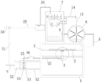
fig. 1 is a schematic structural diagram of a waste gas purification process for lead-acid battery recovery according to the present invention.
Fig. 2 is a schematic structural diagram of a primary purification tank in the waste gas purification process for lead-acid battery recovery according to the present invention.
Fig. 3 is a sectional view (right view) of a primary purification tank in the waste gas purification process for lead-acid battery recycling according to the present invention.
Fig. 4 is a schematic structural diagram of a secondary purification box in the waste gas purification process for lead-acid battery recovery according to the present invention.
Fig. 5 is a schematic connection diagram (viewed from the bottom) of a hollow circular box, a hollow circular ring, a fixed pipe and a connecting pipe in the waste gas purification process for recycling a lead-acid storage battery.
Fig. 6 is an enlarged view of a portion a of fig. 1.
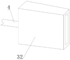
Fig. 7 is a perspective view of a trapezoidal exhaust box in the waste gas purification process for lead-acid battery recycling according to the present invention.
Fig. 8 is a schematic structural diagram of the supporting mechanism in fig. 6.
Fig. 9 is a cross-sectional view of a fixing pipe in the waste gas purification process for lead-acid battery recycling according to the present invention.
Reference numerals: 1. a dust removal box; 2. a fixing plate; 3. a metal dust filter screen; 4. an exhaust gas input pipe; 5. a first gas delivery pipe; 6. a preliminary purification tank; 7. a secondary purification box; 8. a second gas delivery pipe; 9. a rotating shaft; 10. a connecting plate; 11. filtering cloth; 12. an arc-shaped strip; 13. a drive shaft; 14. an output shaft; 15. a purification chamber; 16. an exhaust chamber; 17. a hollow round box; 18. a hollow circular ring; 19. a fixed tube; 20. a liquid ejection hole; 21. a transfusion tube; 22. a third gas delivery pipe; 23. a motor; 24. a connecting pipe; 25. an exhaust fan blade; 26. a fourth gas delivery pipe; 27. a detection box; 28. a gas detection sensor; 29. a fifth gas delivery pipe; 30. an exhaust pipe; 31. an air return pipe; 32. a trapezoidal exhaust box; 33. a movable shaft; 34. a rotor blade; 35. a pull rod; 36. a rotating rod; 37. a movable rod; 38. a slider; 39. a guide rod; 40. a support mechanism; 4001. fixing a column; 4002. inserting a rod; 4003. a spring; 4004. a limiting slide block; 4005. a limiting chute; 41. cleaning with a brush; 42. a connecting box; 43. a liquid baffle plate.
Detailed Description
The technical solutions in the embodiments of the present invention will be clearly and completely described below with reference to the drawings in the embodiments of the present invention, and it is obvious that the described embodiments are only a part of the embodiments of the present invention, and not all of the embodiments. All other embodiments, which can be derived by a person skilled in the art from the embodiments given herein without making any creative effort, shall fall within the protection scope of the present invention.
The first embodiment is as follows:
the invention provides a waste gas purification process for recycling a lead-acid storage battery, which comprises the following steps:
s1, dust filtration treatment: collecting waste gas generated in the recovery process of the lead-acid storage battery, introducing the waste gas into the dust removal box 1 through the waste gas input pipe 4, filtering the waste gas through the metal dust filtering net 3, and enabling filtered lead-containing dust to fall to the inner wall of the bottom of the dust removal box 1;
in the dust filtering process, the trapezoidal exhaust box 32 sprays exhaust gas to the rotating blades 34 through the flat blast holes, the rotating blades 34 drive the movable shaft 33 to rotate under the action of wind force, the pull rod 35 pulls the movable rod 37 to do transverse reciprocating motion through the rotating rod 36, the sliding block 38 does transverse reciprocating motion along the guide rod 39 under the pushing and pulling action of the movable rod 37, the cleaning brush 41 repeatedly brushes the metal dust filtering net 3, and particulate matters blocked in the filtering holes are brushed down;
s2, filtering and deacidifying: the waste gas after dust filtration enters a primary purification tank 6 through a first gas conveying pipe 5, and the waste gas is filtered and deacidified through filter cloth 11 attached with acid gas treatment liquid;
the rotating shaft 9 drives the connecting plate 10 to rotate, the filter cloth 11 rotates along with the connecting plate, and when the filter cloth 11 rotates to the position below the inner part of the primary purification tank 6, the acidic gas treatment liquid in the primary purification tank 6 soaks and cleans the filter cloth 11, so that the filter cloth 11 is kept in a wet state all the time;
s3, deacidifying and purifying: waste gas subjected to preliminary filtering and deacidification enters the purification cavity 15 through the second gas conveying pipe 8, the waste gas in the purification cavity 15 upwards enters each fixed pipe 19, the acid gas treatment liquid is conveyed into the hollow circular ring 18 through the liquid conveying pipe 21, the treatment liquid is conveyed into the liquid collecting cavity in the fixed pipe 19 through each connecting pipe 24 by the hollow circular ring 18, and the treatment liquid is sprayed out of the fixed pipe 19 through the liquid spraying holes 20 on the inner peripheral surface, so that the waste gas is fully contacted with the treatment liquid to achieve complete deacidification;
s4, gas detection processing: the output shaft 14 drives the exhaust fan blade 25 to rotate, the air in the purification cavity 15 is conveyed into the exhaust cavity 16 through the exhaust effect of the exhaust fan blade 25, and the fourth air conveying pipe 26 conveys the air into the detection box 27; the gas detection sensor 28 detects the gas in the detection box 27, and the fifth gas pipe 29 leads the gas in the detection box 27 out;
when the detection result of the processed gas passing through the gas detection sensor 28 reaches a standard, the control valve on the exhaust pipe 30 is opened to exhaust the gas, and when the detection result of the processed gas passing through the gas detection sensor 28 does not reach a standard, the control valve on the muffler 31 is opened to convey the gas into the exhaust gas inlet pipe 4, and then the gas is purified again.
As shown in fig. 1-7, a fixed plate 2 is fixedly installed on the dust removing box 1 through bolts, and a metal dust filtering net 3 is arranged in the middle of the fixed plate 2; the primary purification tank 6 is fixedly installed at the top of the dust removal box 1 through bolts, the secondary purification box 7 is fixedly installed at the top of the dust removal box 1 through bolts, the dust removal box 1 is used for filtering dust of waste gas, a purification cavity 15 and an exhaust cavity 16 are formed in the secondary purification box 7, and the exhaust cavity 16 is located above the purification cavity 15; the first gas pipe 5 is communicated with the dust removal box 1 and the primary purification tank 6, waste gas subjected to dust filtration treatment enters the primary purification tank 6 through the first gas pipe 5, the second gas pipe 8 is communicated with the primary purification tank 6 and the purification cavity 15, waste gas subjected to primary filtration deacidification treatment enters the purification cavity 15 through the second gas pipe 8, the first gas pipe 5 and the second gas pipe 8 are positioned on two sides of the primary purification tank 6, and the communication position of the first gas pipe 5 and the dust removal box 1 is positioned above the metal dust filtration net 3; the detection box 27 is fixedly arranged on the secondary purification box 7 through bolts, and a gas detection sensor 28 is fixedly arranged in the detection box 27 through bolts; the secondary purification box 7 is provided with a fourth air pipe 26 communicated with the exhaust cavity 16, the air in the purification cavity 15 is conveyed into the exhaust cavity 16, the fourth air pipe 26 conveys the air into the detection box 27, the tail end of the fourth air pipe 26 is communicated with the detection box 27, and the fourth air pipe 26 conveys the air into the detection box 27; the detection box 27 is provided with a fifth gas pipe 29, the tail end of the fifth gas pipe 29 is communicated with the exhaust pipe 30 and the air return pipe 31, the fifth gas pipe 29 is used for conveying purified gas to the exhaust pipe 30 or the air return pipe 31, the other end of the air return pipe 31 is communicated with the waste gas input pipe 4, and the exhaust pipe 30 and the air return pipe 31 are respectively provided with a control valve; the gas detection sensor 28 is in communication connection with the processor, the processor is in control connection with the two control valves, the gas detection sensor 28 detects gas in the detection box 27, when the detection result of the processed gas reaches a standard, the control valve on the exhaust pipe 30 is opened to discharge the gas, otherwise, the control valve on the gas return pipe 31 is opened to convey the gas to the waste gas input pipe 4, and the gas is subsequently purified again, so that the waste gas can be effectively treated;
a guide rod 39 is transversely arranged in the dust removal box 1, the guide rod 39 plays a role in guiding, a sliding block 38 is sleeved on the guide rod 39, the sliding block 38 slides along the guide rod 39, a supporting mechanism 40 is arranged at the top of the sliding block 38, a cleaning brush 41 is fixedly installed at the top of the supporting mechanism 40 through a bolt, the supporting mechanism 40 supports the cleaning brush 41, bristles of the cleaning brush 41 are in contact with the bottom of the metal dust filter screen 3, and the cleaning brush 41 automatically brushes the metal dust filter screen 3 to remove particles blocked in filter holes; the dust removal box 1 is fixedly provided with a connecting box 42 communicated with the dust removal box 1 through bolts, one side of the connecting box 42, which is far away from the dust removal box 1, is provided with a trapezoidal exhaust box 32, an exhaust gas input pipe 4 is communicated with the trapezoidal exhaust box 32, the exhaust gas input pipe 4 conveys exhaust gas into the trapezoidal exhaust box 32, and the trapezoidal exhaust box 32 blows the gas into the connecting box 42; the connecting box 42 is rotatably provided with a movable shaft 33, the movable shaft 33 is fixedly provided with a rotating blade 34 through a bolt, the trapezoidal exhaust box 32 is provided with a flat blast hole, the blast direction of the flat blast hole faces the rotating blade 34, the blown waste gas enables the rotating blade 34 to rotate, and the movable shaft 33 rotates along with the flat blast hole; the top end of the movable shaft 33 penetrates through the connecting box 42 and is connected with the pull rod 35, the other end of the pull rod 35 is rotatably connected with the rotating rod 36, and the pull rod 35 rotates along with the movable shaft 33 and pushes and pulls the rotating rod 36; a movable rod 37 is horizontally arranged on the sliding block 38, the other end of the movable rod 37 penetrates out of the dust removal box 1, the rotating rod 36 is rotatably connected with the movable rod 37, the rotating rod 36 deflects and enables the movable rod 37 to transversely reciprocate, and finally the cleaning brush 41 is enabled to repeatedly brush and clean the metal dust filter screen 3, so that the metal dust filter screen 3 is automatically cleaned;
a rotating shaft 9 is rotatably arranged in the primary purification tank 6 through a bearing, the rotating shaft 9 rotates on the primary purification tank 6, a plurality of groups of connecting plates 10 are fixedly mounted on the outer peripheral surface of the rotating shaft 9 through bolts, the connecting plates 10 rotate along with the rotating shaft 9, a filter cloth 11 is arranged in the middle of each connecting plate 10, the filter cloth 11 attached with an acid gas treatment liquid (such as alkali liquor) is contacted with waste gas to preliminarily remove fine particles and acid gas (such as sulfur dioxide), the acid gas treatment liquid is contained in the inner bottom end of the primary purification tank 6, when the filter cloth 11 rotates to the lower part of the inner part of the primary purification tank 6, the acid gas treatment liquid in the primary purification tank 6 soaks and cleans the filter cloth 11, so that the filter cloth 11 is always kept in a wet state, and the filtering deacidification effect of the filter cloth 11 is ensured; an arc-shaped strip 12 is fixedly arranged at one end, far away from the rotating shaft 9, of the connecting plate 10 through bolts, the arc-shaped strip 12 is in contact with the inner circumferential surface of the primary purification tank 6, the arc-shaped strip 12 enables the connecting plate 10 to be tightly attached to the inner wall of the primary purification tank 6, waste gas is favorably guided to one side of the second gas pipe 8 from one side of the first gas pipe 5, and the influence on the treatment effect caused by the fact that gas penetrates through gaps between the first gas pipe and the second gas pipe is avoided;
the top of the purification cavity 15 is fixedly provided with a hollow round box 17 through bolts, purified gas is gathered in the hollow round box 17, the hollow round box 17 is communicated with the exhaust cavity 16 through a third gas pipe 22, and the third gas pipe 22 conveys the gas in the hollow round box 17 into the exhaust cavity 16; the bottom of the hollow round box 17 is provided with a hollow round ring 18, the hollow round ring 18 is provided with a liquid conveying pipe 21 communicated with the hollow round ring 18, the secondary purification box 7 is fixedly provided with a water pump through a mounting seat, the liquid conveying pipe 21 is connected with the output side of the water pump, the input side of the water pump is communicated with a treatment liquid storage box through a pipeline, the water pump conveys the treatment liquid to the liquid conveying pipe 21, the liquid conveying pipe 21 guides the treatment liquid into the hollow round ring 18, the bottom of the hollow round box 17 is vertically provided with a plurality of groups of fixing pipes 19 communicated with the hollow round box, and waste gas in the purification cavity 15 enters each fixing pipe 19; an annular liquid collecting cavity is formed in the fixed pipe 19, the hollow circular ring 18 is communicated with the liquid collecting cavity in the fixed pipe 19 through the connecting pipes 24, treatment liquid in the hollow circular ring 18 is uniformly dispersed into the liquid collecting cavity in each fixed pipe 19 through each connecting pipe 24, liquid spraying holes 20 communicated with the liquid collecting cavity are uniformly formed in the inner peripheral surface of the fixed pipe 19, the treatment liquid is sprayed out through the liquid spraying holes 20, and the sprayed treatment liquid is fully contacted with waste gas, so that acid gas in the waste gas can be effectively absorbed; a motor 23 is fixedly mounted on the secondary purification box 7 through a motor base, an output shaft 14 is mounted at the output end of the motor 23, the motor 23 is used for driving the output shaft 14, a plurality of groups of exhaust fan blades 25 are fixedly mounted on the output shaft 14 through bolts, the output shaft 14 drives the exhaust fan blades 25 to rotate, the exhaust fan blades 25 are located in an exhaust cavity 16, the exhaust fan blades 25 rotate in the exhaust cavity 16 to guide out internal gas, the exhaust direction of the exhaust fan blades 25 faces to an air inlet of a fourth gas pipe 26, and the fourth gas pipe 26 conveys out gas in the exhaust cavity 16; a groove is formed in the primary purification tank 6, and the rotating shaft 9 extends into the groove; install transmission shaft 13 through bearing rotation on the preliminary purifying tank 6, transmission shaft 13 is vertical to be set up and downwardly extending goes into in the recess, and transmission shaft 13 is connected through bevel gear meshing transmission with pivot 9, output shaft 14 wears out secondary purifying box 7 and is connected through bevel gear meshing transmission with transmission shaft 13, output shaft 14 drives transmission shaft 13 and rotates, transmission shaft 13 drives pivot 9 and rotates, finally realizes the rotation of connecting plate 10.
Example two:
as shown in fig. 8, this embodiment is substantially the same as embodiment 1, and preferably, the support mechanism 40 includes a fixed column 4001, an insertion rod 4002, a spring 4003, a limit slider 4004, and a limit chute 4005; the fixed column 4001 is vertically arranged on the sliding block 38, an inserting groove with an upward opening is vertically formed in the fixed column 4001, and the inserting rod 4002 is connected with the cleaning brush 41 and is downwards inserted into the fixed column 4001; spring 4003 is vertical to be set up in fixed column 4001 and is connected with inserted bar 4002's bottom, spring 4003 is in compression state and applys ascending thrust to inserted bar 4002, inserted bar 4002 applys ascending thrust to cleaning brush 41, cleaning brush 41 pushes down metal dust filter net 3 upwards, the particulate matter brush that will block up in the filtration pore when helping automatic cleaning sweeps down, spacing slider 4004 is installed to inserted bar 4002's lateral wall, spacing spout 4005 has vertically been seted up in the fixed column 4001, spacing slider 4004 is located spacing spout 4005 and with fixed column 4001 sliding connection, spacing slider 4004 slides along spacing spout 4005, spacing spout 4005 plays spacing and the effect of direction.
Example three:
as shown in fig. 9, this embodiment is substantially the same as embodiment 1, and preferably, two sets of liquid baffle plates 43 are fixedly mounted in the fixed pipe 19 at positions close to the top end by bolts, the liquid baffle plates 43 are located at two sides of the inside of the fixed pipe 19, and the number of the liquid baffle plates 43 in each set is plural; liquid baffle 43 sets up downwards for the slope, and two sets of liquid baffle 43 along vertical direction interval setting, and gaseous upward movement in fixed pipe 19, wherein liquid baffle 43 that both sides slope set up can keep off down liquid, sets up multiunit liquid baffle 43 through the interval, is showing to improve and keeps off the liquid effect, helps avoiding gaseous taking out of with the treatment fluid.
The working principle of the invention is as follows:
the waste gas input pipe 4 guides the waste gas into the trapezoidal exhaust box 32, the waste gas enters the dust removal box 1 along the connecting box 42, and the metal dust filtering net 3 filters the waste gas to filter lead-containing dust in the waste gas; the trapezoidal exhaust box 32 sprays the exhaust gas to the rotating blade 34 through the flat blast hole, the rotating blade 34 drives the movable shaft 33 to rotate under the action of wind force, finally the sliding block 38 carries out transverse reciprocating motion along the guide rod 39, the cleaning brush 41 carries out repeated brushing on the metal dust filter screen 3, and the particles blocked in the filter holes are brushed and fallen down, so that the metal dust filter screen 3 is automatically cleaned, and the filter holes of the metal dust filter screen 3 are prevented from being blocked to influence the dust filtering effect;
the motor 13 enables the rotating shaft 9 to rotate through the output shaft 14 and the transmission shaft 13, the rotating shaft 9 drives the connecting plate 10 to rotate, the filter cloth 11 rotates along with the rotating shaft, the waste gas subjected to dust filtration treatment enters the primary purification tank 6 through the first gas conveying pipe 5, the filter cloth 11 attached with acid gas treatment liquid (such as alkali liquor) is contacted with the waste gas to primarily remove fine particles and acid gas (such as sulfur dioxide) in the waste gas, and the waste gas is guided to the position of the second gas conveying pipe 8 through the rotation of the connecting plate 10; when the filter cloth 11 rotates to the lower part of the inner part of the primary purification tank 6, the acidic gas treatment liquid in the primary purification tank 6 soaks and cleans the filter cloth 11, so that the filter cloth 11 is always kept in a wet state, and the filtering deacidification effect of the filter cloth 11 is ensured;
waste gas subjected to preliminary filtering and deacidification treatment enters the purification cavity 15 through the second gas conveying pipe 8, the waste gas in the purification cavity 15 upwards enters each fixed pipe 19, the acid gas treatment liquid is conveyed into the hollow circular ring 18 through the liquid conveying pipe 21, the hollow circular ring 18 conveys the treatment liquid into the liquid collecting cavity in the fixed pipe 19 through each connecting pipe 24, the fixed pipe 19 uniformly sprays the treatment liquid through the liquid spraying holes 20 on the inner peripheral surface, the waste gas is fully contacted with the treatment liquid, and the acid gas in the waste gas can be thoroughly removed; output shaft 14 drives exhaust fan blade 25 and rotates, air in will purifying chamber 15 is carried to the chamber 16 of airing exhaust through the effect of airing exhaust of exhaust fan blade 25, fourth gas-supply pipe 26 is with gas transport to in the detection case 27, gas detection sensor 28 detects the gas in the detection case 27, gaseous testing result reaches standard after handling, the control valve on the blast pipe 30 is opened in order to discharge gas, otherwise, the control valve on muffler 31 is opened and with gas transport to in the waste gas input pipe 4, follow-up purification treatment to gas once more, can carry out effective treatment to waste gas, avoid waste gas direct discharge and cause the pollution to the environment.
The foregoing is merely exemplary and illustrative of the present invention and various modifications, additions and substitutions may be made by those skilled in the art to the specific embodiments described without departing from the scope of the invention as defined in the following claims.
In the description herein, references to the description of "one embodiment," "an example," "a specific example" or the like are intended to mean that a particular feature, structure, material, or characteristic described in connection with the embodiment or example is included in at least one embodiment or example of the invention. In this specification, the schematic representations of the terms used above do not necessarily refer to the same embodiment or example. Furthermore, the particular features, structures, materials, or characteristics described may be combined in any suitable manner in any one or more embodiments or examples.
The preferred embodiments of the invention disclosed above are intended to be illustrative only. The preferred embodiments are not intended to be exhaustive or to limit the invention to the precise forms disclosed. Obviously, many modifications and variations are possible in light of the above teaching. The embodiments were chosen and described in order to best explain the principles of the invention and the practical application, to thereby enable others skilled in the art to best utilize the invention. The invention is limited only by the claims and their full scope and equivalents.
Claims (2)
1. The waste gas purification process for recycling the lead-acid storage battery is characterized by comprising the following steps of:
s1, dust filtration treatment: collecting waste gas generated in the recovery process of the lead-acid storage battery, introducing the waste gas into the dust removal box (1) through a waste gas input pipe (4), filtering the waste gas through a metal dust filtering net (3), and enabling filtered lead-containing dust to fall to the inner wall of the bottom of the dust removal box (1);
in the dust filtering process, the trapezoidal exhaust box (32) sprays exhaust gas to the rotating blades (34) through the flat blast holes, the rotating blades (34) drive the movable shaft (33) to rotate under the action of wind power, the pull rod (35) pulls the movable rod (37) to transversely reciprocate through the rotating rod (36), the sliding block (38) transversely reciprocates along the guide rod (39) under the pushing and pulling action of the movable rod (37), the cleaning brush (41) repeatedly brushes the metal dust filtering net (3), and particles blocked in the filtering holes are brushed down;
s2, filtering and deacidifying: the waste gas after dust filtration enters a primary purification tank (6) through a first gas conveying pipe (5), and the waste gas is filtered and deacidified through filter cloth (11) attached with acid gas treatment liquid;
the rotating shaft (9) drives the connecting plate (10) to rotate, the filter cloth (11) rotates along with the rotating shaft, and when the filter cloth (11) rotates to the lower part of the interior of the primary purification tank (6), the acidic gas treatment liquid in the primary purification tank (6) soaks and cleans the filter cloth (11), so that the filter cloth (11) is always kept in a wet state;
s3, deacidifying and purifying: waste gas subjected to primary filtering and deacidification enters a purification cavity (15) through a second gas conveying pipe (8), the waste gas in the purification cavity (15) upwards enters each fixed pipe (19), an acid gas treatment liquid is conveyed into a hollow circular ring (18) through a liquid conveying pipe (21), the treatment liquid is conveyed into a liquid collecting cavity in each fixed pipe (19) through each connecting pipe (24) by the hollow circular ring (18), and the treatment liquid is sprayed out of the fixed pipes (19) through liquid spraying holes (20) in the inner peripheral surface, so that the waste gas is fully contacted with the treatment liquid to achieve complete deacidification;
s4, gas detection processing: the output shaft (14) drives the exhaust fan blade (25) to rotate, the air in the purification cavity (15) is conveyed into the exhaust cavity (16) through the exhaust effect of the exhaust fan blade (25), and the fourth air conveying pipe (26) conveys the air into the detection box (27); the gas detection sensor (28) detects the gas in the detection box (27), and the fifth gas pipe (29) leads out the gas in the detection box (27);
when the detection result of the processed gas passing through the gas detection sensor (28) reaches the standard, a control valve on the exhaust pipe (30) is opened to exhaust the gas, and when the detection result of the processed gas passing through the gas detection sensor (28) does not reach the standard, a control valve on the gas return pipe (31) is opened to convey the gas into the waste gas input pipe (4), and then the gas is purified again;
the dust removal box (1) is fixedly provided with a fixed plate (2) through bolts, and the middle part of the fixed plate (2) is provided with a metal dust filtering net (3); the primary purification tank (6) is fixedly mounted at the top of the dust removal box (1) through bolts, the secondary purification box (7) is fixedly mounted at the top of the dust removal box (1) through bolts, a purification cavity (15) and an air exhaust cavity (16) are formed in the secondary purification box (7), and the air exhaust cavity (16) is located above the purification cavity (15); the first gas pipe (5) is communicated with the dust removal box (1) and the primary purification tank (6), the second gas pipe (8) is communicated with the primary purification tank (6) and the purification cavity (15), the first gas pipe (5) and the second gas pipe (8) are positioned on two sides of the primary purification tank (6), and the communication position of the first gas pipe (5) and the dust removal box (1) is positioned above the metal dust filter screen (3);
the detection box (27) is fixedly arranged on the secondary purification box (7) through bolts, and a gas detection sensor (28) is fixedly arranged in the detection box (27) through bolts; a fourth air conveying pipe (26) communicated with the exhaust cavity (16) is mounted on the secondary purification box (7), and the tail end of the fourth air conveying pipe (26) is communicated with a detection box (27); a fifth air pipe (29) is installed on the detection box (27), the tail end of the fifth air pipe (29) is communicated with an exhaust pipe (30) and an air return pipe (31), the other end of the air return pipe (31) is communicated with the waste gas input pipe (4), and control valves are respectively arranged on the exhaust pipe (30) and the air return pipe (31); the gas detection sensor (28) is in communication connection with the processor, and the processor is in control connection with the two control valves;
a guide rod (39) is transversely arranged in the dust removal box (1), a sliding block (38) is sleeved on the guide rod (39), a supporting mechanism (40) is arranged at the top of the sliding block (38), a cleaning brush (41) is fixedly arranged at the top of the supporting mechanism (40) through a bolt, and bristles of the cleaning brush (41) are in contact with the bottom of the metal dust filter screen (3); a connecting box (42) communicated with the dust removing box (1) is fixedly installed on the dust removing box (1) through bolts, a trapezoidal exhaust box (32) is installed on one side, away from the dust removing box (1), of the connecting box (42), and the waste gas input pipe (4) is communicated with the trapezoidal exhaust box (32); the connecting box (42) is rotatably provided with a movable shaft (33), and the movable shaft (33) is fixedly provided with a rotating blade (34) through a bolt; a flat blast hole is formed in the trapezoidal exhaust box (32), and the blast direction of the flat blast hole faces the rotating blades (34); the top end of the movable shaft (33) penetrates through the connecting box (42) and is connected with the pull rod (35), and the other end of the pull rod (35) is rotatably connected with the rotating rod (36); a movable rod (37) is horizontally arranged on the sliding block (38), the other end of the movable rod (37) penetrates out of the dust removal box (1), and the rotating rod (36) is rotatably connected with the movable rod (37);
the supporting mechanism (40) comprises a fixing column (4001), an inserting rod (4002), a spring (4003), a limiting sliding block (4004) and a limiting sliding groove (4005); the fixed column (4001) is vertically arranged on the sliding block (38), an inserting groove with an upward opening is vertically formed in the fixed column (4001), and the inserting rod (4002) is connected with the cleaning brush (41) and is downwards inserted into the fixed column (4001); the spring (4003) is vertically arranged in a fixed column (4001) and is connected with the bottom of an inserted link (4002), a limiting sliding block (4004) is installed on the side wall of the inserted link (4002), a limiting sliding groove (4005) is vertically formed in the fixed column (4001), and the limiting sliding block (4004) is located in the limiting sliding groove (4005) and is in sliding connection with the fixed column (4001);
a rotating shaft (9) is rotatably arranged in the primary purification tank (6) through a bearing, a plurality of groups of connecting plates (10) are fixedly arranged on the outer peripheral surface of the rotating shaft (9) through bolts, filter cloth (11) is arranged in the middle of each connecting plate (10), and acid gas treatment liquid is filled in the bottom end of the interior of the primary purification tank (6); an arc-shaped strip (12) is fixedly installed at one end, far away from the rotating shaft (9), of the connecting plate (10) through bolts, and the arc-shaped strip (12) is in contact with the inner circumferential surface of the primary purification tank (6);
the top of the purification cavity (15) is fixedly provided with a hollow round box (17) through a bolt, and the hollow round box (17) is communicated with the exhaust cavity (16) through a third air conveying pipe (22); a hollow circular ring (18) is arranged at the bottom of the hollow circular box (17), an infusion tube (21) communicated with the hollow circular ring (18) is arranged on the hollow circular ring (18), and a plurality of groups of fixing tubes (19) communicated with the hollow circular ring (17) are vertically arranged at the bottom of the hollow circular box (17); an annular liquid collecting cavity is formed in the fixed pipe (19), the hollow circular ring (18) is communicated with the liquid collecting cavity in the fixed pipe (19) through a connecting pipe (24), and liquid spraying holes (20) communicated with the liquid collecting cavity are uniformly formed in the inner circumferential surface of the fixed pipe (19);
a motor (23) is fixedly mounted on the secondary purification box (7) through a motor base, an output shaft (14) is mounted at the output end of the motor (23), a plurality of groups of exhaust fan blades (25) are fixedly mounted on the output shaft (14) through bolts, the exhaust fan blades (25) are positioned in the exhaust cavity (16), and the exhaust direction of the exhaust fan blades (25) faces to an air inlet of a fourth air conveying pipe (26);
a groove is formed in the primary purification tank (6), and the rotating shaft (9) extends into the groove; the primary purification tank (6) is rotatably provided with a transmission shaft (13) through a bearing, the transmission shaft (13) is vertically arranged and extends downwards into the groove, the transmission shaft (13) is in meshing transmission connection with the rotating shaft (9) through a bevel gear, and an output shaft (14) penetrates out of the secondary purification tank (7) and is in meshing transmission connection with the transmission shaft (13) through the bevel gear.
2. The waste gas purification process for recycling the lead-acid storage battery is characterized in that two groups of liquid baffles (43) are arranged in the fixed pipe (19) near the top end, the liquid baffles (43) are positioned at two sides of the inner part of the fixed pipe (19), and the number of the liquid baffles (43) in each group is multiple; the liquid blocking plates (43) are obliquely arranged downwards, and the two groups of liquid blocking plates (43) are arranged at intervals in the vertical direction.
Priority Applications (1)
| Application Number | Priority Date | Filing Date | Title |
|---|---|---|---|
| CN202110717733.7A CN113413702B (en) | 2021-06-28 | 2021-06-28 | Waste gas purification process for recycling lead-acid storage battery |
Applications Claiming Priority (1)
| Application Number | Priority Date | Filing Date | Title |
|---|---|---|---|
| CN202110717733.7A CN113413702B (en) | 2021-06-28 | 2021-06-28 | Waste gas purification process for recycling lead-acid storage battery |
Publications (2)
| Publication Number | Publication Date |
|---|---|
| CN113413702A CN113413702A (en) | 2021-09-21 |
| CN113413702B true CN113413702B (en) | 2022-08-23 |
Family
ID=77717032
Family Applications (1)
| Application Number | Title | Priority Date | Filing Date |
|---|---|---|---|
| CN202110717733.7A Active CN113413702B (en) | 2021-06-28 | 2021-06-28 | Waste gas purification process for recycling lead-acid storage battery |
Country Status (1)
| Country | Link |
|---|---|
| CN (1) | CN113413702B (en) |
Families Citing this family (7)
| Publication number | Priority date | Publication date | Assignee | Title |
|---|---|---|---|---|
| CN114198768A (en) * | 2021-12-13 | 2022-03-18 | 无锡翔龙环球科技股份有限公司 | Flue type waste heat recycling device |
| CN114225685B (en) * | 2021-12-28 | 2023-07-11 | 广州市溢涌环保工程有限公司 | Be applied to desulfurization denitrification facility of environmental protection dust removal |
| CN114083197A (en) * | 2022-01-18 | 2022-02-25 | 江苏三尔汽车部件有限公司 | Welding device for machining automobile shock absorber accessory |
| CN114832542B (en) * | 2022-04-18 | 2022-10-14 | 广州正禹环保科技有限公司 | Environment-friendly flue gas purification treatment equipment for garbage disposal |
| CN114632382B (en) * | 2022-04-20 | 2024-09-20 | 南通久奇环保节能工程有限公司 | Waste gas treatment device with energy-saving and environment-friendly functions |
| CN114949968B (en) * | 2022-05-24 | 2023-11-10 | 道道全粮油靖江有限公司 | Industrial water purification tower convenient to wash |
| CN118217793B (en) * | 2024-05-27 | 2024-07-19 | 中国科学技术大学 | Waste gas recovery treatment method for lithium battery disassembly |
Citations (7)
| Publication number | Priority date | Publication date | Assignee | Title |
|---|---|---|---|---|
| JPH07155512A (en) * | 1993-09-06 | 1995-06-20 | Kyung-Suk Lim | Filter using chaff |
| CN111135657A (en) * | 2018-11-05 | 2020-05-12 | 江苏宇光电源科技有限公司 | Waste gas discharge device among lead acid battery |
| CN211357875U (en) * | 2019-07-31 | 2020-08-28 | 庄勇波 | Domestic sewage treatment equipment |
| CN111992020A (en) * | 2020-09-04 | 2020-11-27 | 太和县大华能源科技有限公司 | Tail gas treatment process for recycling lead-acid storage battery |
| CN112007437A (en) * | 2020-09-09 | 2020-12-01 | 太和县大华能源科技有限公司 | Tail gas dust collector in lead acid battery recovery technology |
| CN212214733U (en) * | 2020-04-21 | 2020-12-25 | 重庆汇光饲料有限公司 | Cowshed sewage treatment plant |
| CN112843968A (en) * | 2021-01-30 | 2021-05-28 | 郑州睿强实验设备有限公司 | Solid-state flue gas treatment device for chemical experiment |
-
2021
- 2021-06-28 CN CN202110717733.7A patent/CN113413702B/en active Active
Patent Citations (7)
| Publication number | Priority date | Publication date | Assignee | Title |
|---|---|---|---|---|
| JPH07155512A (en) * | 1993-09-06 | 1995-06-20 | Kyung-Suk Lim | Filter using chaff |
| CN111135657A (en) * | 2018-11-05 | 2020-05-12 | 江苏宇光电源科技有限公司 | Waste gas discharge device among lead acid battery |
| CN211357875U (en) * | 2019-07-31 | 2020-08-28 | 庄勇波 | Domestic sewage treatment equipment |
| CN212214733U (en) * | 2020-04-21 | 2020-12-25 | 重庆汇光饲料有限公司 | Cowshed sewage treatment plant |
| CN111992020A (en) * | 2020-09-04 | 2020-11-27 | 太和县大华能源科技有限公司 | Tail gas treatment process for recycling lead-acid storage battery |
| CN112007437A (en) * | 2020-09-09 | 2020-12-01 | 太和县大华能源科技有限公司 | Tail gas dust collector in lead acid battery recovery technology |
| CN112843968A (en) * | 2021-01-30 | 2021-05-28 | 郑州睿强实验设备有限公司 | Solid-state flue gas treatment device for chemical experiment |
Also Published As
| Publication number | Publication date |
|---|---|
| CN113413702A (en) | 2021-09-21 |
Similar Documents
| Publication | Publication Date | Title |
|---|---|---|
| CN113413702B (en) | Waste gas purification process for recycling lead-acid storage battery | |
| CN212166837U (en) | Filter equipment for nitrogen generator | |
| CN117046236A (en) | Industrial dust removal equipment for environmental protection | |
| CN219128837U (en) | Exhaust-gas treatment spray column that can prevent jam | |
| CN218221648U (en) | Dust collection box for TFT glass kiln gas treatment | |
| CN214764019U (en) | Dust removal box for flue gas desulfurization and denitration | |
| CN214019841U (en) | Desulfurization dust collecting equipment | |
| CN213590072U (en) | Energy-saving and environment-friendly equipment for waste gas treatment | |
| CN115318029A (en) | Miniature dust remover | |
| CN213408054U (en) | Air purification device for dust-free workshop | |
| CN213221561U (en) | Glass steel workshop is with high-efficient gas removal structure | |
| CN113230825A (en) | Self-cleaning newly-developed waste gas emission treatment equipment for atmosphere pollution prevention and control | |
| CN221156015U (en) | Carbon processing desulfurization dust collector | |
| CN215654370U (en) | Flue dust remover | |
| CN220878195U (en) | Dust waste gas treatment device | |
| CN220657070U (en) | Desulfurizing agent regenerating device | |
| CN220779693U (en) | Dry quenching Jiao Weiqi desulfurization dust remover | |
| CN215712451U (en) | Anaerobic tank that intelligence was prevented blockking up | |
| CN220939291U (en) | Ammonium carbonate effluent treatment plant | |
| CN220283990U (en) | Dry quenching dust recycling device | |
| CN216457564U (en) | Treatment device for atmospheric combined pollution | |
| CN221333251U (en) | Efficient automatic waste gas removing device for paint production | |
| CN220758439U (en) | Dust removal purification device for recovery treatment of waste lead-acid storage battery | |
| CN212700962U (en) | Glass fiber dust collector is used in soda production | |
| CN220142904U (en) | Waste gas absorbing and treating device |
Legal Events
| Date | Code | Title | Description |
|---|---|---|---|
| PB01 | Publication | ||
| PB01 | Publication | ||
| SE01 | Entry into force of request for substantive examination | ||
| SE01 | Entry into force of request for substantive examination | ||
| GR01 | Patent grant | ||
| GR01 | Patent grant | ||
| PE01 | Entry into force of the registration of the contract for pledge of patent right | ||
| PE01 | Entry into force of the registration of the contract for pledge of patent right |
Denomination of invention: A waste gas purification process for lead-acid battery recycling Granted publication date: 20220823 Pledgee: Anhui Taihe rural commercial bank Limited by Share Ltd. Pledgor: TAIHE DAHUA ENERGY TECHNOLOGY CO.,LTD. Registration number: Y2024980029615 |