CN113401755B - Elevator inspection system with robotic platform configured with platform mover - Google Patents
Elevator inspection system with robotic platform configured with platform mover Download PDFInfo
- Publication number
- CN113401755B CN113401755B CN202011396671.6A CN202011396671A CN113401755B CN 113401755 B CN113401755 B CN 113401755B CN 202011396671 A CN202011396671 A CN 202011396671A CN 113401755 B CN113401755 B CN 113401755B
- Authority
- CN
- China
- Prior art keywords
- controller
- hoistway
- robotic platform
- platform
- robotic
- Prior art date
- Legal status (The legal status is an assumption and is not a legal conclusion. Google has not performed a legal analysis and makes no representation as to the accuracy of the status listed.)
- Active
Links
Images


Classifications
-
- B—PERFORMING OPERATIONS; TRANSPORTING
- B66—HOISTING; LIFTING; HAULING
- B66B—ELEVATORS; ESCALATORS OR MOVING WALKWAYS
- B66B5/00—Applications of checking, fault-correcting, or safety devices in elevators
- B66B5/0006—Monitoring devices or performance analysers
- B66B5/0018—Devices monitoring the operating condition of the elevator system
- B66B5/0025—Devices monitoring the operating condition of the elevator system for maintenance or repair
-
- B—PERFORMING OPERATIONS; TRANSPORTING
- B66—HOISTING; LIFTING; HAULING
- B66B—ELEVATORS; ESCALATORS OR MOVING WALKWAYS
- B66B5/00—Applications of checking, fault-correcting, or safety devices in elevators
- B66B5/0006—Monitoring devices or performance analysers
- B66B5/0018—Devices monitoring the operating condition of the elevator system
- B66B5/0031—Devices monitoring the operating condition of the elevator system for safety reasons
-
- B—PERFORMING OPERATIONS; TRANSPORTING
- B66—HOISTING; LIFTING; HAULING
- B66B—ELEVATORS; ESCALATORS OR MOVING WALKWAYS
- B66B5/00—Applications of checking, fault-correcting, or safety devices in elevators
- B66B5/0006—Monitoring devices or performance analysers
- B66B5/0018—Devices monitoring the operating condition of the elevator system
-
- B—PERFORMING OPERATIONS; TRANSPORTING
- B25—HAND TOOLS; PORTABLE POWER-DRIVEN TOOLS; MANIPULATORS
- B25J—MANIPULATORS; CHAMBERS PROVIDED WITH MANIPULATION DEVICES
- B25J5/00—Manipulators mounted on wheels or on carriages
- B25J5/005—Manipulators mounted on wheels or on carriages mounted on endless tracks or belts
-
- B—PERFORMING OPERATIONS; TRANSPORTING
- B25—HAND TOOLS; PORTABLE POWER-DRIVEN TOOLS; MANIPULATORS
- B25J—MANIPULATORS; CHAMBERS PROVIDED WITH MANIPULATION DEVICES
- B25J5/00—Manipulators mounted on wheels or on carriages
- B25J5/007—Manipulators mounted on wheels or on carriages mounted on wheels
-
- B—PERFORMING OPERATIONS; TRANSPORTING
- B25—HAND TOOLS; PORTABLE POWER-DRIVEN TOOLS; MANIPULATORS
- B25J—MANIPULATORS; CHAMBERS PROVIDED WITH MANIPULATION DEVICES
- B25J5/00—Manipulators mounted on wheels or on carriages
- B25J5/02—Manipulators mounted on wheels or on carriages travelling along a guideway
-
- B—PERFORMING OPERATIONS; TRANSPORTING
- B25—HAND TOOLS; PORTABLE POWER-DRIVEN TOOLS; MANIPULATORS
- B25J—MANIPULATORS; CHAMBERS PROVIDED WITH MANIPULATION DEVICES
- B25J9/00—Programme-controlled manipulators
- B25J9/16—Programme controls
- B25J9/1679—Programme controls characterised by the tasks executed
-
- B—PERFORMING OPERATIONS; TRANSPORTING
- B64—AIRCRAFT; AVIATION; COSMONAUTICS
- B64B—LIGHTER-THAN AIR AIRCRAFT
- B64B1/00—Lighter-than-air aircraft
- B64B1/40—Balloons
-
- B—PERFORMING OPERATIONS; TRANSPORTING
- B64—AIRCRAFT; AVIATION; COSMONAUTICS
- B64C—AEROPLANES; HELICOPTERS
- B64C39/00—Aircraft not otherwise provided for
- B64C39/02—Aircraft not otherwise provided for characterised by special use
- B64C39/024—Aircraft not otherwise provided for characterised by special use of the remote controlled vehicle type, i.e. RPV
-
- B—PERFORMING OPERATIONS; TRANSPORTING
- B66—HOISTING; LIFTING; HAULING
- B66B—ELEVATORS; ESCALATORS OR MOVING WALKWAYS
- B66B1/00—Control systems of elevators in general
- B66B1/34—Details, e.g. call counting devices, data transmission from car to control system, devices giving information to the control system
- B66B1/3415—Control system configuration and the data transmission or communication within the control system
- B66B1/3423—Control system configuration, i.e. lay-out
-
- B—PERFORMING OPERATIONS; TRANSPORTING
- B66—HOISTING; LIFTING; HAULING
- B66B—ELEVATORS; ESCALATORS OR MOVING WALKWAYS
- B66B19/00—Mining-hoist operation
- B66B19/002—Mining-hoist operation installing or exchanging guide rails
-
- B—PERFORMING OPERATIONS; TRANSPORTING
- B66—HOISTING; LIFTING; HAULING
- B66B—ELEVATORS; ESCALATORS OR MOVING WALKWAYS
- B66B5/00—Applications of checking, fault-correcting, or safety devices in elevators
- B66B5/0006—Monitoring devices or performance analysers
-
- B—PERFORMING OPERATIONS; TRANSPORTING
- B66—HOISTING; LIFTING; HAULING
- B66B—ELEVATORS; ESCALATORS OR MOVING WALKWAYS
- B66B5/00—Applications of checking, fault-correcting, or safety devices in elevators
- B66B5/0087—Devices facilitating maintenance, repair or inspection tasks
-
- G—PHYSICS
- G05—CONTROLLING; REGULATING
- G05D—SYSTEMS FOR CONTROLLING OR REGULATING NON-ELECTRIC VARIABLES
- G05D1/00—Control of position, course or altitude of land, water, air, or space vehicles, e.g. automatic pilot
- G05D1/0094—Control of position, course or altitude of land, water, air, or space vehicles, e.g. automatic pilot involving pointing a payload, e.g. camera, weapon, sensor, towards a fixed or moving target
-
- B—PERFORMING OPERATIONS; TRANSPORTING
- B64—AIRCRAFT; AVIATION; COSMONAUTICS
- B64D—EQUIPMENT FOR FITTING IN OR TO AIRCRAFT; FLIGHT SUITS; PARACHUTES; ARRANGEMENTS OR MOUNTING OF POWER PLANTS OR PROPULSION TRANSMISSIONS IN AIRCRAFT
- B64D47/00—Equipment not otherwise provided for
- B64D47/08—Arrangements of cameras
-
- B—PERFORMING OPERATIONS; TRANSPORTING
- B64—AIRCRAFT; AVIATION; COSMONAUTICS
- B64U—UNMANNED AERIAL VEHICLES [UAV]; EQUIPMENT THEREFOR
- B64U10/00—Type of UAV
- B64U10/10—Rotorcrafts
- B64U10/13—Flying platforms
-
- B—PERFORMING OPERATIONS; TRANSPORTING
- B64—AIRCRAFT; AVIATION; COSMONAUTICS
- B64U—UNMANNED AERIAL VEHICLES [UAV]; EQUIPMENT THEREFOR
- B64U2101/00—UAVs specially adapted for particular uses or applications
- B64U2101/30—UAVs specially adapted for particular uses or applications for imaging, photography or videography
-
- B—PERFORMING OPERATIONS; TRANSPORTING
- B64—AIRCRAFT; AVIATION; COSMONAUTICS
- B64U—UNMANNED AERIAL VEHICLES [UAV]; EQUIPMENT THEREFOR
- B64U2201/00—UAVs characterised by their flight controls
- B64U2201/20—Remote controls
Abstract
An elevator inspection system is disclosed, the system having: a robotic platform configured to inspect a hoistway; a platform mover operably coupled to the robotic platform; and a controller operatively connected to the platform mover, wherein the controller is configured to control the platform mover to vertically propel the robotic platform within the hoistway.
Description
Technical Field
An elevator inspection system is disclosed, and more particularly to an elevator inspection system having a sensor fixture supported by a robot or robot platform.
Background
Manually mapping the elevator shaft to install the elevator system can take a significant amount of time and can be inaccurate. Also, manual inspection of an elevator hoistway with an installed elevator system can take a significant amount of time and can be inaccurate. There is a need for a solution for reducing the manual power required for these activities.
Disclosure of Invention
Disclosed is an elevator inspection system having: a sensor device; a robotic platform supporting the sensor, the robotic platform configured to inspect the hoistway; a controller operatively connected to the robotic platform and the sensor, wherein the controller is configured to define hoistway model data about the hoistway based on the sensor data, the data corresponding to a location and shape boundary of the hoistway and a doorway opening formed in the hoistway.
Additionally or alternatively to one or more aspects of the system, the controller is configured to define a three-dimensional hoistway model from the hoistway model data.
Additionally or alternatively to one or more aspects of the system above, the controller is configured to use the hoistway model data as a reference point to install and/or maintain one or more components in the hoistway.
Additionally or alternatively to one or more aspects of the system, the controller is configured to define elevator car guide rail data corresponding to the virtual elevator guide rail in the hoistway model data.
Additionally or alternatively to one or more aspects of the system, the controller is configured to determine a sill-to-sill distance, a rail-to-rail distance, and a sill-to-rail distance for each hoistway opening based on hoistway model data.
Additionally or alternatively to one or more aspects of the system, the controller is configured to determine a tilt and twist of the hoistway, a position and a size of the doorway opening, based on hoistway model data.
Additionally or alternatively to one or more aspects of the system, the controller is configured to define a mounting location within hoistway model data of the elevator component.
Additionally or alternatively to one or more aspects of the system, the controller is configured to control movement of the robotic platform in the hoistway, wherein the controller is manually operated on a SLAM (simultaneous localization and mapping) and/or CAD (computer aided design) model.
Additionally or alternatively to one or more aspects of the system above, the sensor appliance is one or more of: a video sensor; a sound sensor; a LIDAR sensor; a camera; a laser sensor; photogrammetric sensors, and time-of-flight sensors.
Additionally or alternatively to one or more aspects of the system above, the robotic platform is a drone.
Further disclosed is a method of forming hoistway model data about a hoistway, the method comprising defining, by a controller, hoistway model data about the hoistway corresponding to a position and shape boundary of an elevator hoistway shaft and a doorway opening formed in the elevator hoistway shaft from sensor hardware supported by a robotic platform, wherein the robotic platform is configured to inspect the hoistway, and wherein the controller controls the robotic platform and the sensor hardware.
Additionally or alternatively to one or more aspects of the method, the method includes defining, by the controller, a three-dimensional hoistway model from the hoistway model data.
Additionally or alternatively to one or more aspects of the method, the method includes utilizing, by the controller, the hoistway model data as a reference point to install and/or maintain one or more components in the hoistway.
Additionally or alternatively to one or more aspects of the method, the method includes defining, by the controller, elevator car guide rail data corresponding to the virtual elevator guide rail in the hoistway model data.
In addition or alternatively to one or more of the above aspects of the method, the method comprises: the sill-to-sill distance, rail-to-rail distance, and sill-to-rail distance for each hoistway opening is determined by the controller based on hoistway model data.
Additionally or alternatively to one or more aspects of the method, the method includes determining, by the controller, a tilt and twist of the hoistway, a position and a size of the doorway opening based on the hoistway model data.
Additionally or alternatively to one or more aspects of the method, the method includes defining, by the controller, a mounting location within hoistway model data of an elevator component including the virtual guide rail.
Additionally or alternatively to one or more aspects of the method, the method includes controlling movement of the robotic platform in the hoistway by a controller, wherein the controller is manually operated on a SLAM (simultaneous localization and mapping) and/or CAD (computer aided design) model.
Additionally or alternatively to one or more aspects of the method above, the sensor device is one or more of: a video sensor; a sound sensor; a LIDAR sensor; a camera; a laser sensor; photogrammetric sensors, and time-of-flight sensors.
Additionally or alternatively to one or more aspects of the method, the robotic platform is a drone.
Further disclosed is an elevator inspection system having: a sensor device; a robotic platform supporting a sensor fixture, the robotic platform configured to inspect a hoistway; and a controller operatively connected to the robotic platform and the sensor device, wherein the controller is configured to define hoistway model data about the hoistway based on maintenance and performance data collected from the elevator systems connected to the different locations that are in communication by means of the network.
Additionally or alternatively to one or more aspects of the system, the controller is configured to define hoistway model data from maintenance and performance data collected over the internet and use cloud computing for analysis.
Additionally or alternatively to one or more aspects of the system, the controller is configured to identify maintenance and performance trends based on the collected maintenance and performance data.
Additionally or alternatively to one or more aspects of the system above, the controller is configured to define hoistway model data to include, for an elevator car in the hoistway, one or more of: maintenance requirements; ride quality; a motion profile; and door performance.
Additionally or alternatively to one or more aspects of the system, the controller is configured to determine a frequency of monitoring the hoistway based on the hoistway model data.
Additionally or alternatively to one or more aspects of the system, the controller is configured to determine to monitor the hoistway substantially continuously based on the hoistway model data.
Additionally or alternatively to one or more aspects of the system, the controller is configured to further define hoistway model data based on the sensed location and shape boundaries of the hoistway and the doorway opening formed in the hoistway.
Additionally or alternatively to one or more aspects of the system, the controller is configured to define hoistway model data including a sill-to-sill distance, a rail-to-rail distance, a sill-to-rail distance, and a tilt and twist of the hoistway.
Additionally or alternatively to one or more aspects of the system above, the controller is configured to use the hoistway model data as a reference point to install and/or maintain one or more components in the hoistway.
Additionally or alternatively to one or more aspects of the system, the controller is configured to send an alert upon identifying that a component of an elevator system installed in the hoistway is positioned or operated outside of predetermined positioning and operating tolerances based on sensor data compared to hoistway model data.
Further disclosed is a method of determining whether a component of an elevator system is positioned and operated within predetermined positioning and operating tolerances, the method comprising: hoistway model data about the hoistway is defined by the controller from maintenance and performance data collected from elevator systems connected to different locations that rely on network communication, wherein the controller is operably connected to a robotic platform that supports the sensor fixture, and wherein the robotic platform is configured to inspect the hoistway.
Additionally or alternatively to one or more aspects of the method, the method includes defining, by the controller, hoistway model data from maintenance and performance data collected over the internet, and using cloud computing for analysis.
Additionally or alternatively to one or more aspects of the method, the method includes identifying, by the controller, maintenance and performance trends based on the collected maintenance and performance data.
Additionally or alternatively to one or more aspects of the method, the method includes defining, by the controller, hoistway model data to include, for an elevator car in the hoistway, one or more of: maintenance requirements; ride quality; a motion profile; and door performance.
Additionally or alternatively to one or more aspects of the method, the method includes determining, by the controller, a frequency of monitoring the hoistway based on the hoistway model data.
Additionally or alternatively to one or more aspects of the method, the method includes determining, by the controller, that the hoistway is monitored substantially continuously based on the hoistway model data.
Additionally or alternatively to one or more aspects of the method, the method includes further defining, by the controller, hoistway model data as a function of the sensed location and shape boundaries of the hoistway and the doorway opening formed in the hoistway.
Additionally or alternatively to one or more aspects of the method, the method includes defining, by the controller, hoistway model data including a sill-to-sill distance, a rail-to-rail distance, a sill-to-rail distance, and a tilt and twist of the hoistway.
Additionally or alternatively to one or more aspects of the method, the method includes utilizing, by the controller, the hoistway model data as a reference point to install and/or maintain one or more components in the hoistway.
In addition or alternatively to one or more of the above aspects of the method, the method comprises: an alert is sent by the controller upon identifying that a component of an elevator system installed in the hoistway is positioned or operating outside of predetermined positioning and operating tolerances based on the sensor data compared to hoistway model data.
Further disclosed is an elevator inspection system having: a sensor device; a robotic platform, the robotic platform being portable, the robotic platform supporting a sensor fixture, the robotic platform configured for inspection and maintenance in a hoistway; a controller is operably connected to the robotic platform and the sensor device, wherein the controller is configured to: controlling the movement of the robot platform in the hoistway; and inspecting one or more components in the hoistway to determine from the sensor data compared to the hoistway model data that the operating parameters or alignment of the one or more components is outside of predetermined positioning and operating tolerances.
Additionally or alternatively to one or more aspects of the system above, the controller is configured to use the hoistway model data as a reference point to install and/or maintain one or more components in the hoistway.
Additionally or alternatively to one or more aspects of the system above, the controller is configured to control the robotic platform to perform one or more of: realignment of the rails; rope/belt inspection; testing riding quality; door coupling alignment inspection; door switch testing; and threshold cleaning to determine that the operating parameters or alignment of the components are outside predetermined positioning and operating tolerances.
Additionally or alternatively to one or more aspects of the system, the controller is configured to determine a current position of the component relative to Global Positioning System (GPS) data.
Additionally or alternatively to one or more aspects of the system, the controller is configured to engage a segment of an elevator guide rail of the hoistway shaft to position the segment within predetermined positioning and operating tolerances when it is determined from sensor data compared to hoistway model data that the segment is positioned outside of the predetermined positioning and operating tolerances.
Additionally or alternatively to one or more aspects of the system, the controller is configured to engage the rail by loosening the rail-fixing bolt, aligning the rail, and tightening the rail-fixing bolt.
Additionally or alternatively to one or more aspects of the system above, the controller is configured to engage one or more components periodically or within a predetermined time frame to determine that the operating parameters or alignment of the components are outside of predetermined positioning and operating tolerances.
Additionally or alternatively to one or more aspects of the system, the controller is configured to define the hoistway model data based on sensed location and shape boundaries of the hoistway shaft and a doorway opening formed in the hoistway shaft.
Additionally or alternatively to one or more aspects of the system, the controller is configured to define hoistway model data including a sill-to-sill distance, a rail-to-rail distance, a sill-to-rail distance, and a tilt and twist of the hoistway.
Additionally or alternatively to one or more aspects of the system, the controller is configured to define the hoistway model data as a three-dimensional model of the hoistway.
Further disclosed is a method of performing maintenance within a hoistway, comprising: the controller controls the robot platform to be controlled by the controller; and inspecting, by the controller, one or more components in the hoistway to determine, based on the sensor data compared to the hoistway model data, that an operating parameter or alignment of the one or more components is outside of a predetermined positioning and operating tolerance, wherein the robotic platform is configured to inspect and perform maintenance at the hoistway, and wherein the controller is operably connected to the robotic platform and a sensor fixture supported by the robotic platform, and wherein the sensor fixture is configured to obtain the sensor data.
Additionally or alternatively to one or more aspects of the method, the method includes utilizing, by the controller, the hoistway model data as a reference point to install and/or maintain one or more components in the hoistway.
Additionally or alternatively to one or more aspects of the method, the method includes controlling, by the controller, the robotic platform to perform one or more of: realignment of the rails; rope/belt inspection; testing riding quality; door coupling alignment inspection; door switch testing; and threshold cleaning to determine that the operating parameters or alignment of the components are outside predetermined positioning and operating tolerances.
Additionally or alternatively to one or more aspects of the method, the method includes determining, by the controller, a current position of the component relative to Global Positioning System (GPS) data.
Additionally or alternatively to one or more aspects of the method, the method includes engaging, by the controller, a segment of an elevator guide rail of the hoistway shaft to position the segment within predetermined positioning and operating tolerances when it is determined from sensor data compared to hoistway model data that the segment is positioned outside of the predetermined positioning and operating tolerances.
In addition or alternatively to one or more of the above aspects of the method, the method comprises: the rail is engaged by the controller by loosening the rail-fixing bolts, aligning the rail and tightening the rail-fixing bolts.
Additionally or alternatively to one or more aspects of the method, the method includes engaging, by the controller, one or more components periodically or within a predetermined time frame to determine that an operating parameter or alignment of the components is outside a predetermined positioning and operating tolerance.
Additionally or alternatively to one or more aspects of the method, the method includes defining, by the controller, hoistway model data based on the sensed location and shape boundaries of the hoistway shaft and the doorway opening formed in the hoistway shaft.
Additionally or alternatively to one or more aspects of the method, the method includes defining, by the controller, hoistway model data including a sill-to-sill distance, a rail-to-rail distance, a sill-to-rail distance, and a tilt and twist of the hoistway.
Additionally or alternatively to one or more aspects of the method, the method includes defining, by the controller, the hoistway model data as a three-dimensional model of the hoistway.
Further disclosed is an elevator inspection system having: a robotic platform configured to inspect a hoistway; a platform mover operably coupled to the robotic platform; and a controller operatively connected to the platform mover, wherein the controller is configured to control the platform mover to vertically propel the robotic platform within the hoistway.
Additionally or alternatively to one or more aspects of the system, the controller is configured to control a friction pulley operatively connected between the robot platform and a rope extending to the machine room atop the hoistway, thereby propelling the robot platform.
Additionally or alternatively to one or more aspects of the system, the controller is configured to control a vacuum chuck operatively connected between the robot platform and a sidewall of the hoistway to propel the robot platform.
Additionally or alternatively to one or more aspects of the system, the controller is configured to control a rubber wheel operatively connected between the robot platform and the hoistway sidewall to propel the robot platform.
Additionally or alternatively to one or more aspects of the system, the controller is configured to control a mechanical leg operably connected between the robot platform and the hoistway sidewall to propel the robot platform.
Additionally or alternatively to one or more aspects of the system above, the controller is configured to control a pusher operably connected to the robotic platform, wherein the robotic platform is supported by the balloon, thereby pushing the robotic platform.
Additionally or alternatively to one or more aspects of the system, the controller is configured to control a track climber operatively connected to the robotic platform to propel the robotic platform.
Additionally or alternatively to one or more aspects of the system, the controller is configured to control a track climber operatively connected to the robotic platform, wherein the track climber operatively engages a first track adjacent the first hoistway sidewall, and a balance of the track climber operatively positions against the second hoistway sidewall, thereby propelling the robotic platform.
Additionally or alternatively to one or more aspects of the system above, the controller is configured to control the drone as or operably connected to the robotic platform to propel the robotic platform.
Additionally or alternatively to one or more aspects of the system above, the controller is configured to control one or more controllable tools supported on the robotic platform, thereby configuring the robotic platform for scanning and inspecting the hoistway, making measurements, sanding, marking drilling points, and drilling.
Further disclosed is a method of propelling a robotic platform within a hoistway, the method comprising: the platform mover is controlled by the controller to vertically advance the robotic platform within the hoistway, wherein the robotic platform is configured to inspect the hoistway, the platform mover is operatively connected to the robotic platform, and the controller is operatively connected to the platform mover.
Additionally or alternatively to one or more aspects of the method, the method includes controlling, by the controller, a friction sheave operatively connected between the robot platform and a rope extending to a machine room atop the hoistway, thereby propelling the robot platform.
Additionally or alternatively to one or more aspects of the method, the method includes controlling, by the controller, a vacuum chuck operatively connected between the robot platform and the hoistway sidewall, thereby propelling the robot platform.
Additionally or alternatively to one or more aspects of the method, the method includes controlling, by the controller, a rubber wheel operatively connected between the robot platform and the hoistway sidewall to propel the robot platform.
Additionally or alternatively to one or more aspects of the method, the method includes controlling, by the controller, a mechanical leg operatively connected between the robot platform and the hoistway sidewall to propel the robot platform.
Additionally or alternatively to one or more aspects of the method, the method includes controlling, by the controller, a pusher operably connected to the robotic platform, wherein the robotic platform is supported by the balloon, thereby pushing the robotic platform.
Additionally or alternatively to one or more aspects of the method, the method includes controlling, by the controller, a track climber operably connected to the robotic platform to propel the robotic platform.
Additionally or alternatively to one or more aspects of the method, the method includes controlling, by the controller, a track climber operably connected to the robotic platform, wherein the track climber operably engages a first track adjacent the first hoistway sidewall, and a balance of the track climber operably positions against the second hoistway sidewall, thereby propelling the robotic platform.
Additionally or alternatively to one or more aspects of the method, the method includes controlling, by the controller, the drone as or operably connected to the robotic platform to propel the robotic platform.
Additionally or alternatively to one or more of the above aspects of the method, the method includes controlling, by the controller, one or more controllable tools supported on the robotic platform, thereby configuring the robotic platform for scanning and inspecting the hoistway, making measurements, sanding, marking drilling points, and drilling.
Further disclosed is an elevator inspection system configured to inspect a plurality of elevator cars in a group of elevator cars, the system having: a sensor device; a robot that supports the sensor instrument; and a controller operatively connected to the robot and the sensor, wherein the controller is configured to send an alarm in response to determining from the sensor data compared to the elevator operation data that an operation parameter of an elevator car in which the robot is located is outside a predetermined threshold.
Additionally or alternatively to one or more aspects of the system, the controller is configured to determine whether the ride quality is outside a predetermined threshold, thereby determining that the operating parameter is outside the predetermined threshold.
Additionally or alternatively to one or more aspects of the system, the controller is configured to determine whether the acceleration is outside a predetermined threshold, thereby determining that the ride quality is outside the predetermined threshold.
Additionally or alternatively to one or more aspects of the system, the controller is configured to determine whether the operating sound is outside a predetermined threshold, thereby determining that the ride quality is outside the predetermined threshold.
Additionally or alternatively to one or more aspects of the system, the controller is configured to communicate with the elevator car control panel to determine that the operating parameter is outside of a predetermined threshold.
Additionally or alternatively to one or more aspects of the system, the controller is configured to instruct the elevator car control panel to perform one or more of a run between levels, an emergency stop, and an open/close door cycle, thereby determining that the operating parameter is outside of a predetermined threshold.
Additionally or alternatively to one or more aspects of the system above, the controller is configured to: verifying operation of the COP lamp; confirming the leveling precision of an elevator car; cleaning an elevator car via a robot; and/or altering elevator car controller settings to minimize impact on floor ride quality.
Additionally or alternatively to one or more aspects of the system, the controller is configured to communicate with the elevator car control panel over a wireless network.
Additionally or alternatively to one or more aspects of the system, the controller is configured to control the sensor appliance to obtain sensor data during a predetermined period of time and/or when the elevator car is free of passengers.
Additionally or alternatively to one or more of the aspects above, the controller on board the robot is configured to send an alert to the elevator group controller via the cellular network.
Further disclosed is a method of performing elevator operation inspection using a robot, comprising: an alert is sent by the controller in response to determining from the sensor data compared to the elevator operation data that an operation parameter of an elevator car in which the robot is located is outside a predetermined threshold, wherein the controller is operatively connected to the robot and a sensor appliance supported by the robot, and wherein the controller is configured to control the sensor appliance to obtain the sensor data.
Additionally or alternatively to one or more aspects of the method, the method includes determining, by the controller, whether the ride quality is outside a predetermined threshold, thereby determining that the operating parameter is outside the predetermined threshold.
Additionally or alternatively to one or more aspects of the method, the method includes determining, by the controller, whether the acceleration is outside a predetermined threshold, thereby determining that the ride quality is outside the predetermined threshold.
Additionally or alternatively to one or more aspects of the method, the method includes determining, by the controller, whether the operating sound is outside a predetermined threshold, thereby determining that the ride quality is outside the predetermined threshold.
Additionally or alternatively to one or more aspects of the method, the method includes communicating, by the controller, with the elevator car control panel to determine that the operating parameter is outside of a predetermined threshold.
Additionally or alternatively to one or more aspects of the method, the method includes instructing, by the controller, the elevator car control panel to perform one or more of a run between levels, an emergency stop, and an open/close door cycle, thereby determining that the operating parameter is outside of a predetermined threshold.
Additionally or alternatively to one or more aspects of the method, the method includes verifying, by the controller, operation of the COP lamp; confirming the leveling precision of the elevator car by a controller; cleaning, by a controller, the elevator car via a robot; and/or altering the settings of the elevator car controller by the controller to minimize the impact of floor ride quality.
Additionally or alternatively to one or more aspects of the method, the method includes communicating, by the controller, with the elevator car control panel over a wireless network.
Additionally or alternatively to one or more aspects of the method, the method includes controlling, by the controller, the sensor appliance to obtain sensor data during a predetermined period of time and/or when the elevator car is free of passengers.
Additionally or alternatively to one or more aspects of the method, the method includes sending, by the controller onboard the robot, an alert to the elevator group controller over the cellular network.
Drawings
The present disclosure is illustrated by way of example and is not limited by the accompanying figures, in which like references indicate similar elements.
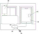
Fig. 1 is a schematic diagram of an elevator system in which various embodiments of the present disclosure may be employed;
fig. 2 shows a robot platform in a hoistway to form a model for installation;
fig. 3 is a close-up view of a robotic platform in a hoistway;
fig. 4 illustrates additional aspects of a robotic platform in a hoistway to form a model for installation;
fig. 5 is a flow chart illustrating a method of forming hoistway model data regarding a hoistway;
fig. 6 is a flow chart illustrating a method of determining whether components of an installed elevator system are operating within a predetermined positional tolerance based on utilization of a data set collected, for example, over the internet;
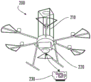
Fig. 7 shows a robot platform for engaging elevator guide rails positioned outside of tolerances, wherein the robot platform is located at the bottom of a hoistway;
fig. 8 shows a robot platform for engaging elevator guide rails positioned outside of tolerances, with the robot platform centered along the height of the hoistway;
fig. 9 shows a robot platform for engaging elevator guide rails positioned outside of tolerances, with the robot platform centered along the height of the hoistway;
fig. 10 is a flow chart illustrating a method of performing maintenance in a hoistway;
FIG. 11 illustrates a platform mover formed as a controllable friction pulley;
FIG. 12 illustrates a platform mover formed as a controllable vacuum chuck;
FIG. 13 shows a platform mover formed as a controllable rubber wheel;
FIG. 14 illustrates a platform mover formed as a controllable mechanical leg;
FIG. 15 shows a platform mover formed as a controllable mover, wherein the robotic platform is supported by a balloon;
FIG. 16 illustrates a platform mover formed as a track climber;
FIG. 17 shows a platform mover formed as a track climbing device configured with a balance wheel;
fig. 18 shows a platform propeller formed as a drone;
fig. 19 is a flow chart illustrating a method of propelling a robotic platform in a hoistway;
Fig. 20 shows an inspection robot for an elevator system; and
fig. 21 is a flowchart showing a method of performing elevator operation inspection using a mobile robot.
Detailed Description
Fig. 1 is a perspective view of an elevator system 101 that includes an elevator car 103, a counterweight 105, a tension member 107, guide rails 109, a machine 111, a position reference system 113, and a controller 115. The elevator car 103 and the counterweight 105 are connected to each other by a tensioning member 107. The tensioning member 107 may include or be configured as, for example, a rope, a steel cord, and/or a coated steel belt. The counterweight 105 is configured to balance the load of the elevator car 103 and is configured to facilitate movement of the elevator car 103 within the (elevator shaft) hoistway 117 and along the guide rails 109 simultaneously and in opposite directions relative to the counterweight 105.
Tensioning member 107 engages machine 111, which is part of the overhead structure of elevator system 101. Machine 111 is configured to control movement between elevator car 103 and counterweight 105. The position reference system 113 may be mounted on a fixed portion of the top of the hoistway 117, such as on a support or guide rail, and may be configured to provide a position signal related to the position of the elevator car 103 within the hoistway 117. In other embodiments, position reference system 113 may be mounted directly to a moving component of machine 111, or may be located in other positions and/or configurations known in the art. As known in the art, the position reference system 113 may be any device or mechanism for monitoring the position of an elevator car and/or counterweight. As will be appreciated by those skilled in the art, for example and without limitation, the position reference system 113 may be an encoder, a sensor appliance, or other system, and may include speed sensing, absolute position sensing, and the like.
As shown, the controller 115 is located in a controller room 121 of the hoistway 117 and is configured to control operation of the elevator system 101, and in particular the elevator car 103. For example, controller 115 may provide drive signals to machine 111 to control acceleration, deceleration, leveling, stopping, etc. of elevator car 103. The controller 115 may also be configured to receive a position signal from the position reference system 113 or any other desired position reference device. As moving up or down the guide rail 109 within the hoistway 117, the elevator car 103 may stop at one or more landings 125 under the control of the controller 115. Although shown in controller room 121, one skilled in the art will recognize that controller 115 may be located and/or configured at other locations or positions within elevator system 101. In one embodiment, the controller may be located remotely or in the cloud.
Although shown and described with a roping system comprising a tension member 107, an elevator system employing other methods and mechanisms for moving an elevator car within an elevator hoistway can employ embodiments of the present disclosure. For example, embodiments may be used in ropeless elevator systems that use linear motors to impart motion to an elevator car. Embodiments may also be used in ropeless elevator systems that use a hydraulic elevator to impart motion to an elevator car. Fig. 1 is a non-limiting example given for illustration and explanation purposes only.
The following figures illustrate additional features associated with one or more disclosed embodiments. Features disclosed in the following figures having similar terms to those disclosed in fig. 1 may be similarly interpreted, although numerical identifiers that may be different from those in fig. 1 are certainly re-introduced. Furthermore, the process steps disclosed below may be numbered sequentially to facilitate discussion of one or more disclosed embodiments. Such numbering is not intended to identify a particular order of performing such steps or a particular requirement of performing such steps unless explicitly so stated.
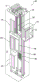
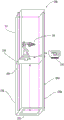
Turning to fig. 2-4, an elevator inspection system (inspection system) 200 is shown that may be used to install an elevator system in a hoistway 117. The inspection system 200 provides high accuracy over the entire height (or length) of the hoistway 117. The inspection system 200 includes a position reference system that is able to accurately identify the height of the hoistway 117 as well as the twist (or rotation) and tilt (or bend). Inspection system 200 includes one sensor fixture 210 (or more than one sensor fixture 210, including peripheral and on-board sensor fixtures, etc.) that is capable of defining a reliable reference point, which is advantageous for robotic systems to define hoistway data, which may represent a three-dimensional (3D) hoistway model (e.g., a virtual model). The hoistway data may be used as reference data for installing, upgrading, maintaining and/or inspecting the elevator system.
The inspection system 200 includes a robotic platform 220 movable along the hoistway 117. The hoistway data may be embedded in electronics stored in a platform controller (controller) 230 on the robotic platform 220. The reference system may be an earlier defined map of the hoistway 117, serving as a reference point. Alternatively, the controller 230 may define the map using software such as computer aided engineering or design (CAE or CAD) software as it travels, such as a laser (one-dimensional, two-dimensional, or three-dimensional scanning may be utilized), a camera, or an acoustic sensor. Inspection system 200 may allow for identification of height, sill-to-sill, rail-to-door, rail-to-rail, wall-to-wall measurements. The collected data may be used for installation, inspection or service. By using a high precision position robot, the robotic platform can be equipped with power tools and perform precise tasks.
Benefits of the disclosed embodiments include reduced time to market for elevator systems, time for mechanics, competitive advantages provided by elevator systems based on quick and accurate installation, increased installation accuracy, extended product life, and improved installation quality and ride quality.
In fig. 2-3, the robotic platform 220 is a drone, while in fig. 4, the robotic platform 220 is shown supporting a robotic arm 250. In this context, reference to one form of robotic platform (or robotic arm) is not intended to limit the type of robotic platform (or robotic arm) used in inspection system 200. The robotic platform 220 may be equipped with sensor fixtures 210 suitable for reference and scanning operations, including but not limited to stereoscopic cameras, acoustic sensors, LIDAR (light and radar detection) sensors, photogrammetry sensors, laser sensors, which allow for the establishment of a substantially complete three-dimensional image of the hoistway 117. Well measurements of well data are obtained from an inspection system 200 within the well. The measurements include rail-to-rail, door width, hoistway depth and width, rail-to-rail, etc., which would otherwise be performed manually for each landing in the hoistway.
In addition, elevator mechanics may wish to receive hoistway dimensions from a general contractor to check whether the installed elevator system 101 is built and maintained according to predetermined specifications. A hoistway model that may have been formed prior to initial installation of elevator system 101 may be used as a reference system to virtually mark the installation location of substantially each component in hoistway 117. The hoistway model may be used to identify deflection (twist/tilt) in the hoistway 117 and damage to the hoistway 117, which is not readily available through manual discrete landing measurements.
According to one embodiment, inspection system 200 may be used in different applications for elevator installation and subsequent service. The disclosed application may be beneficial for saving time and cost, which may result in higher field efficiency. As indicated, the measurements made by the inspection system 200 include three-dimensional models showing the inclination, distortion, and/or deformation of the hoistway (e.g., defects in the structure), rail-to-rail measurements, rail-to-sill measurements, sill-to-sill measurements, and the like. These measurements provide references to specific landing and global reference points. The robotic platform 220 may be stationary (e.g., located in the hoistway pit 225 or on a landing) or may move in the hoistway 117.
Benefits of the disclosed embodiments include reduced field time for a mechanic to find and solve problems during and after installation, thereby providing a competitive advantage while also improving the accuracy of the elevator car 103 and extending the useful life of the product. System performance tracking is also enhanced. A global database for condition-based monitoring (CBM) and predictive maintenance may also be performed. The reference system and global database (discussed in detail below) defined by the hoistway model may allow for accurate installation of equipment in the hoistway 117. The robotic platform 220 may be used to map the hoistway 117 at a higher resolution than that obtained by discrete landing measurements alone. The disclosed system may allow for the use of advanced automated commercial off-the-shelf solutions, such as robotic arms.
Thus, as shown (fig. 2-4), the elevator inspection system includes a sensor fixture 210 and a robotic platform 220 supporting the sensor fixture 210, wherein the robotic platform 220 is configured to inspect the hoistway 117. A controller 230 is operably connected to the robotic platform 220 and the sensor device 210. In one embodiment, sensor fixture 210 is a video sensor and/or an acoustic sensor. In one embodiment, the robotic platform 220 is a drone.
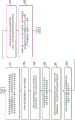
Turning to fig. 5, a method for forming hoistway model data for a hoistway 117 is disclosed. The hoistway 117 may not yet include an elevator system (elevator car 103, guide rails 109, etc.), and a hoistway model may be used for the installation process. Alternatively, the hoistway 117 may include an elevator system (elevator car 103, guide rails 109, etc.), and the hoistway model may be used for inspection and maintenance.
As shown in block 510, the method includes the controller 230 defining hoistway model data for the hoistway 117 from the sensor data, the data corresponding to the location and shape boundaries (at various levels) of the hoistway 117 and the doorway opening formed in the hoistway 117.
As shown in block 510A, the method includes the controller 230 defining a three-dimensional hoistway model from hoistway model data.
As shown in block 510B, the method includes the controller 230 utilizing the hoistway model data as a reference point for installing and/or maintaining one or more components in the hoistway.
As shown in block 510C, the method includes the controller 230 defining elevator car guide rail data corresponding to the virtual elevator guide rail 109 in the hoistway model data. That is, in the case where the elevator system has not yet been installed, the model will include virtual elevator guide rails at the location where the actual elevator guide rails 109 are to be installed.
As shown in block 520, the method includes the controller 230 determining a sill-to-sill distance, a rail-to-rail distance, and a sill-to-rail distance for each hoistway opening based on hoistway model data.
As shown in block 520A, the method includes the controller 230 determining a tilt and twist of the hoistway 117, a position and a size of the doorway opening, based on the hoistway model data.
As shown in block 530, the method includes the controller 230 defining (e.g., marking) a mounting location of an elevator component within the hoistway model data, the elevator component including a virtual guide rail.
According to some embodiments, the model comprises a three-dimensional model representation of the hoistway. The model may also include a CAD model or video rendering of the hoistway. In further embodiments, the model may include a rendering of elevator components, including a series of components for elevator installation.
As shown in block 540, the method includes a controller controlling movement of the robotic platform 220 in the hoistway 117 in which the controller is manually operated on a SLAM (simultaneous localization and mapping) and/or CAD model. As described above, in some embodiments, robotic platform 220 is stationary.
According to another aspect of the disclosed embodiments, in the growing internet of things (IoT) market, data is a valuable asset. Having readily accessible information about system performance and operating parameters, as well as a self-diagnosable system, may add value to the field. In addition, historical performance data, trends, and patterns from local, regional, and global tests performed on elevator systems can be used to monitor the quality and service performance of elevator systems.
Thus, with inspection system 200, different types of measurements can be collected to obtain a set of variables that define system operating performance in different phases of operation of elevator system 101. Such measurements include, for example, straightness of the hoistway 117, landing-to-landing (sill-to-sill) measurements, three-dimensional models of the hoistway 117, rail-to-rail 109,109A (fig. 4) measurements, and wall-to-wall 228,228A measurements. Collecting this data allows for significant time savings in the field. Maintenance, ride quality, movement profile, door performance, amount of light in the car, cab Operating Panel (COP) buttons can all be monitored and maintained based on the recorded data. The system performance can be monitored continuously or periodically without the need for on-site mechanics, allowing for cost savings and sales of new products.
As described herein, the benefits of utilizing data are reduced time to market, saved time to mechanic, competitive advantages due to reduced labor costs, improved accuracy, and improved safety to the mechanic. Embodiments enable the creation of a digital database of global measurements, which will improve the design approach and enable new products and services.
Thus, as indicated (fig. 2-4), inspection system 200 includes a sensor fixture 210, a robotic platform 220 supporting sensor fixture 210, and a controller 230 operatively connected to robotic platform 220 and sensor fixture 210. Sensor fixture 210 may be one or more of the following: a video sensor; a sound sensor; LIDAR (light and radar) sensors; a camera; a laser sensor; photogrammetric sensors, and time-of-flight sensors. As shown, the robotic platform 220 is configured for inspecting the hoistway 117.
Turning to fig. 6, a flow chart illustrates a method of determining whether components of installed elevator system 101 are positioned and operated within predetermined positioning and operating tolerances based on, for example, use of a data set collected via the internet.
As shown in block 610, the method includes the controller 230 defining hoistway model data regarding the hoistway 117 based on maintenance and performance data collected from elevator systems connected to different locations that are in communication by means of a network. The hoistway model data may be used to build a virtual model for a new installation of the elevator system.
As shown in block 610A, the method includes the controller 230 defining hoistway model data from maintenance and performance data collected over the internet.
As shown in block 610B, the method includes the controller 230 identifying maintenance and performance trends from the collected maintenance and performance data.
As shown in block 610C, the method includes the controller 230 defining hoistway model data to identify one or more of the following for the elevator car 103 in the hoistway 117: maintenance requirements; ride quality; a motion profile; and door performance requirements.
As shown in block 620, the method includes the controller 230 determining a frequency of monitoring the hoistway 117 based on the hoistway model data.
As shown in block 620A, the method includes the controller determining to monitor the hoistway 117 substantially continuously based on the hoistway model data.
As shown in block 630, the method includes the controller 230 also defining hoistway model data as a function of the sensed location and shape boundaries of the hoistway 117 and the doorway opening formed in the hoistway 117.
As shown in block 630A, the method includes a controller 230 defining hoistway model data including a sill-to-sill distance, a rail-to-rail distance, a sill-to-rail distance, and a tilt and twist of the hoistway. In one embodiment, the hoistway model data defines a three-dimensional model of the hoistway 117.
As shown in block 630B, the method includes the controller 230 utilizing the hoistway model data as a reference point for installing and/or maintaining one or more components in the hoistway.
As shown in block 640, the method includes: an alert is sent by the controller 230 upon identifying that a component of the elevator system installed in the hoistway 117 is positioned or operated outside of predetermined positioning and operating tolerances based on the sensor data compared to the hoistway model data. In one embodiment, the member is a rail 109.
According to another aspect of the disclosed embodiments, accurate hoistway measurements are important for maintenance purposes. The mechanic may receive the hoistway assignments from the general contractor and check whether components in the hoistway 117 are installed and/or operating according to specifications. If the mechanic establishes a reference system and marks the installation location of each component in the hoistway, the mechanic may not be aware of whether there is an incline to the hoistway from this process.
The disclosed embodiments utilize a reference system for elevator installation and subsequent service to provide a measurement application for robotic platform 220. The described utilization is advantageous for saving time and cost, thereby improving field efficiency.
Turning to fig. 7-9, as one example, maintenance of rails that require realignment is shown. Such maintenance may include loosening the bolts, aligning the rails 109, and then tightening the bolts. Other examples may include rope/belt inspection and maintenance, periodic and planned ride quality testing, door coupler alignment, door opening and closing testing, and sill cleaning. The robotic platform 220 is allocated/mounted in the hoistway 117, or a portable device is provided, for example, that can be mounted in the hoistway 117, for example on a rail. In an alternative embodiment, the mechanical arm 250 may be mounted to the top of the elevator car.
The disclosed embodiments have the benefit of reducing the field time of the mechanic, improving the safety of the mechanic by allowing the robot platform to be used in relatively dangerous locations, achieving a competitive advantage based on less machine man-hours required for maintenance, improving accuracy and extending the product life of the life elevator system. In addition, a global database of system performance tracking and CBM and predictive maintenance is provided.
For example, in fig. 7, as the robotic platform 220 moves height along the hoistway 117, the robotic platform 220 is controlled to loosen each rail 109 and adjust and tighten each rail 109. During this process, the robotic platform 220 may perform a test run on each rail 109 to verify the adjustment using the sensor devices 210, which may be one or more on-board ride quality sensor devices. The maintenance process may be repeated over the entire length of each rail 109, if desired, or may be performed along discrete sections of each rail 109.
The robotic platform 220 may be entirely autonomous, or may be provided with mechanic support. Other applications of the maintenance process may include hoistway door service, rope inspection, and door coupler alignment. One non-limiting example is to support a robotic arm 250 (fig. 7-9) on the robotic platform 220. However, the robotic platform 220 may be adapted for tasks and may have a set of tools that may be changed.
As indicated (fig. 2-5 and 7-9), the elevator inspection system includes a sensor fixture 210, a portable robotic platform 220 supporting the sensor fixture 210, and a controller operatively connected to the robotic platform 220 and the sensor fixture 210. As shown, the robotic platform 220 is configured for inspection and maintenance in the hoistway 117.
Turning to fig. 10, a flow chart illustrates a method of performing maintenance within a hoistway 117.
As shown in block 1010, the method includes the controller 230 controlling movement of the robotic platform 220 in the hoistway 117.
As shown in block 1020, the method includes the controller 230 inspecting one or more components in the hoistway 117 to determine from the sensor data compared to the hoistway model data that the operating parameters or alignment of the one or more components is outside of predetermined positioning and operating tolerances. One of ordinary skill will recognize such tolerances.
As shown in block 1020A, the method includes the controller 230 utilizing the hoistway model data as a reference point for installing and/or maintaining one or more components in the hoistway.
As shown in block 1030, the method includes the controller 230 controlling the robotic platform 220 to perform one or more of: realignment of the rails; rope/belt inspection; testing riding quality; door coupling alignment inspection; door switch testing; and threshold cleaning to determine that the operating parameters or alignment of the components are outside predetermined positioning and operating tolerances.
As shown in block 1030A, the method includes the controller 230 engaging a segment 245 of an elevator guide rail 109 of the hoistway 117 to position the segment 245 within predetermined positioning and operating tolerances when it is determined from sensor data compared to hoistway model data that the segment 245 is positioned outside of the predetermined positioning and operating tolerances.
As shown in block 1030B, the method includes the controller 230 engaging the rail 109 by loosening the rail fixation bolts, aligning the rail, and tightening the rail fixation bolts.
As shown in block 1040, the method includes the controller 230 engaging one or more components periodically or within a planned time frame to determine that the operating parameters or alignment of the components are outside of predetermined positioning and operating tolerances.
As shown in block 1050, the method includes the controller defining hoistway model data based on sensed location and shape boundaries of the hoistway and the doorway opening formed in the hoistway.
As shown in block 1050A, the method includes a controller defining hoistway model data including a sill-to-sill distance, a rail-to-rail distance, a sill-to-rail distance, and a tilt and twist of the hoistway 117. In one embodiment, the hoistway model data defines a three-dimensional model of the hoistway 117.
As shown in block 1050B, the method includes the controller 230 defining the hoistway model data as a three-dimensional model of the hoistway 117.
In accordance with another aspect of the disclosed embodiments, robotic platform 220 implements best practices and provides opportunities for a mechanic on site to simplify, support, and/or automate tasks and improve overall site efficiency. The robotic platform 220 is equipped with different tools for installation and service tasks to allow for a partially or fully automated, more time consuming procedure, such as installation and maintenance of the rails.
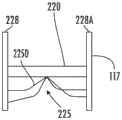
Turning to fig. 11-18, different solutions for propelling the robotic platform 220 are shown, with emphasis on propulsion, safety, and anchoring of the robotic platform in the hoistway 117. The robotic platform 220 may operate in the empty hoistway 117 from a landing or pit and may move in the hoistway 117 using walls or dedicated ropes to move within the hoistway 117. The tool-equipped robotic platform 220 may be used to scan/inspect the hoistway 117, make measurements, polish, mark drilling points, drill holes, lift, or secure rail/door access within the hoistway 117. The robotic platform 220 may be self-propelled or elevated. The guide rail 109 may serve as a guide for the robotic platform 220. The robot platform 220 may be locked in position along the hoistway 117 using brakes on the robot platform 220 or the rail 109. When there are no rails, the robotic platform 220 may use friction against the hoistway walls 228,228A (fig. 4) to lock in place or, if possible, against the ropes.
The robotic platform 220 may be used for one or more of installation, maintenance, and inspection. For example, the robotic platform 220 may be used for belt/rope monitoring, rail straightening, post-seismic hoistway inspection.
Benefits of the disclosed embodiments include reduced product time to market, reduced mechanic time, competitive advantages from lower associated costs, increased accuracy and extended product life, increased mechanical safety, reduced repetitive motion injuries, and a faster design approach.
Each propulsion system shown in fig. 11-18 may function based on decisions that may be performed at the edge of the doorway or wirelessly (e.g., through the internet). Each propulsion system may be equipped with a remote control safety system. In addition, a reference system, such as a global positioning system or hoistway model data, may be used to assist in guiding each propulsion system.
As shown in fig. 11-18, the inspection system 200 includes a robotic platform 220 configured to inspect the hoistway 117, a platform mover 255 operatively connected to the robotic platform 220, and a controller 230 (shown only in fig. 11 for simplicity) operatively connected to the platform mover.
Turning to fig. 19, a flow chart illustrates a method of propelling a robotic platform 220 within a hoistway 117.
As shown in block 1910, the method includes the controller 230 controlling the platform mover 255 to move (e.g., vertically) the robotic platform 220 within the hoistway 117.
As shown in block 1910A, the method includes the controller 230 controlling a friction pulley 255A (fig. 11) operatively connected between the robotic platform 220 and a rope 255A1 extending to a machine room 256 atop the hoistway 117 (and pit 225), thereby propelling the robotic platform 220.
As shown in block 1910B, the method includes the controller 230 controlling a vacuum chuck 225B (fig. 12) operatively connected between the robot platform 220 and the hoistway sidewall 228,228A to propel the robot platform 220.
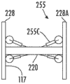
As shown in block 1910C, the method includes the controller 230 controlling a rubber wheel 255C (fig. 13) operatively connected between the robot platform 220 and the hoistway sidewall 228,228A to propel the robot platform 220.
As shown in block 1910D, the method includes the controller 230 controlling a mechanical leg 255D (fig. 14; forming a spider-like set of supports) operatively connected between the robotic platform 220 and the hoistway sidewall 228,228A to propel (e.g., by reversing) the robotic platform.
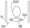
As shown in block 1910E, the method includes the controller 230 controlling a pusher 255E (fig. 15) operatively connected to the robotic platform 220, wherein the robotic platform 220 is supported by the balloon 255E1, thereby pushing the robotic platform 220.
As shown in block 1910F, the method includes the controller 230 controlling a track climber 255F (fig. 16) operatively connected to the robotic platform 220 to propel the robotic platform 220.
As shown in block 1910G, the method includes the controller 230 controlling a track climber 255F (fig. 17) operatively connected to the robotic platform 220, wherein the track climber 255F operatively engages the first track 109 adjacent the first hoistway sidewall 228, and a counterweight 255F1 of the track climber 255F operatively positions against the second hoistway sidewall 228A, thereby propelling the robotic platform 220.
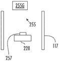
As shown in block 1920, the method includes the controller 230 controlling the drone 255G (fig. 18; shown schematically; see robotic platform 220 in fig. 2) that is or is operably connected to the robotic platform 220 to propel the robotic platform 220.
As shown in block 1930, the method includes the controller 230 controlling one or more controllable tools 257 (fig. 18; shown schematically) supported on the robotic platform 220, whereby the robotic platform 220 is configured to scan and inspect the hoistway 117 for measurements, sanding, marking drilling points, and drilling.
According to another aspect of the disclosed embodiments, and turning to fig. 20, the disclosed embodiments provide a mobile robot (robot 260 for simplicity) that may also be considered a robotic platform. The robot 260 is able to monitor, clean, adjust elevator parameters, measure performance, and request maintenance of the elevator car 103 or elevator group in the building. The robot 260 is configured to perform tests using the built-in sensor fixture 210, such as cameras (to monitor sill conditions and landing alignment), accelerometers, and/or microphones (to monitor ride quality). The robot 260 is able to communicate with the elevator car 103 and perform operation, emergency stop, open/close door cycles and modify basic parameters. The robot 260 may also perform measurements during predetermined time conditions (e.g., off-peak, no passengers). Robot 260 may or may not be equipped with a propulsion device and may or may not require manual intervention to move between elevator cars. The inspection system 200 of this embodiment may utilize an internal or external gateway that connects to the phone using a different protocol, such as Bluetooth Low Energy (BLE), and then uses a cellular protocol, such as global system for mobile communications (GSM), to bridge the robot 260 to the internet.
Benefits of the disclosed embodiments include reduced field time for the mechanic, automatic periodic testing and system tuning, continuous system performance tracking, historical database supporting CBM, and development of predictive maintenance. A competitive advantage may be gained from reduced operating costs and increased startup and uptime.
Thus, the disclosed embodiments provide a non-propelled robot 260 to perform maintenance tasks, such as, for example, as a robotic helper. Robot 260 may communicate with elevator system 101 to issue commands, as well as support sensor appliances 210, such as cameras and ride quality sensors (accelerometers and/or microphones). Robot 260 may examine and make recommendations for routine maintenance tasks.
As shown in the figure (fig. 20), an elevator inspection system 200 configured to inspect a plurality of elevator cars in a group of elevator cars is disclosed that includes a sensor fixture 210, a robot 260 supporting the sensor fixture 210, and a controller 230 operatively connected to the robot and the sensor. The robot 260 is configured to be positioned in the elevator car 103.
Fig. 21 is a flowchart illustrating a method of elevator operation inspection using the robot 260.
As shown in block 2110, the method includes the controller 230 determining that an operating parameter of the elevator car 103 in which the robot 260 is located is outside a predetermined threshold (where the threshold will be understood by a person of ordinary skill), such as sending an alert to a mechanic, in response to sensor data from a comparison to elevator operating data.
As shown in block 2110A, the method includes the controller 230 determining whether the ride quality is outside a predetermined threshold, thereby determining that the operating parameter is outside the predetermined threshold.
As shown in block 2110B, the method includes the controller 230 determining whether the acceleration is outside a predetermined threshold, thereby determining that the ride quality is outside the predetermined threshold.
As shown in block 2110C, the method includes the controller 230 determining whether the operating sound is outside a predetermined threshold, thereby determining that the ride quality is outside the predetermined threshold.
As shown in block 2110D, the method includes the controller 230 communicating with the elevator car control panel 270 to determine that the operating parameter is outside a predetermined threshold.
As shown in block 2110E, the method includes the controller directing the elevator car control panel to perform one or more of a run, an emergency stop, and an open/close door cycle between levels, thereby determining that the operating parameter is outside of a predetermined threshold.
As shown in block 2120, the method includes the controller 230: verifying operation of a Car Operating Panel (COP) lamp; confirming the leveling precision of the elevator car; cleaning an elevator car via a robot; and/or altering elevator car controller settings to minimize impact on floor ride quality.
As shown in block 2130, the method includes the controller 230 communicating with the elevator car control panel 270 over a wireless network, which may be a personal area network.
As shown in block 2140, the method includes the controller 230 controlling the sensor appliance to obtain sensor data for a predetermined period of time and/or when the elevator car is passenger free.
As shown in block 2150, the method includes the controller 230 on the robot 260 sending an alert to the elevator group controller through the cellular network 280.
As used herein, an elevator controller may be a microprocessor-based controller that controls many aspects of elevator operation. A series of sensor appliances, controllers, operating sequences, and real-time calculations or algorithms can balance passenger demand and car availability. The elevator sensor appliances may provide data regarding car position, car movement direction, load, door status, hall calls, car calls, pending hall and hall calls, number of runs per car, alarms, etc. The controller may also have the function of testing the system without stopping the elevator. Based on the collected data, the management system, which is comprised of workstations and software applications, can create metrics for a group or particular car, such as total number of doors open, number of runs per car or call, hall calls up and down, etc. Some performance indicators may be related to passenger waiting time and/or elevator car travel time. These metrics may represent inadequate control, configuration errors, and even equipment failure. Elevator monitoring may be provided as a software as a service (SaaS). Monitoring may identify faults or abnormal operating parameters and automatically dispatch technicians and/or provide alarms to relevant personnel, such as the house owner. Some systems may provide a client control panel accessible via a web browser and/or provide information to owners such as performance summaries and maintenance histories. As shown, an elevator controller may be in communication with one or more elevators by a Controller Area Network (CAN) bus. CAN is a vehicle bus standard that allows microcontrollers and devices to communicate with each other in an application without a host. CAN is a message-based protocol promulgated by the International Standard Organization (ISO). Downstream communications from the elevator system controller may be through the LAN.
As described above, embodiments may take the form of processor-implemented processes and apparatuses for practicing those processes, e.g., processors. Embodiments may also be in the form of computer program code containing instructions embodied in tangible media, such as network cloud storage, SD cards, flash drives, floppy diskettes, CD ROMs, hard drives, or any other computer-readable storage medium, wherein, when the computer program code is loaded into and executed by a computer, the computer becomes an apparatus for practicing the embodiments. Embodiments may also be in the form of computer program code, for example, whether stored in a storage medium, loaded into and/or executed by a computer, or transmitted over some transmission medium, such as over electrical wiring or cabling, through fiber optics, or via electromagnetic radiation, wherein, when the computer program code is loaded into and/or executed by a computer, the computer becomes an apparatus for practicing the embodiments. When implemented on a general-purpose microprocessor, the computer program code segments configure the microprocessor to create specific logic circuits.
The terminology used herein is for the purpose of describing particular embodiments only and is not intended to be limiting of the disclosure. As used herein, the singular forms "a", "an" and "the" are intended to include the plural forms as well, unless the context clearly indicates otherwise. It will be further understood that the terms "comprises" and/or "comprising," when used in this specification, specify the presence of stated features, integers, steps, operations, elements, and/or components, but do not preclude the presence or addition of one or more other features, integers, steps, operations, elements, components, and/or groups thereof.
Those skilled in the art will appreciate that various example embodiments are shown and described herein, each having certain features in a particular embodiment, but the disclosure is not so limited. Rather, the disclosure can be modified to incorporate any number of variations, alterations, substitutions, combinations, sub-combinations or equivalent arrangements not heretofore described, but which are commensurate with the scope of the disclosure. Additionally, while various embodiments of the disclosure have been described, it is to be understood that aspects of the disclosure may include only some of the described embodiments. Accordingly, the disclosure is not to be seen as limited by the foregoing description, but is only limited by the scope of the appended claims.
Claims (20)
1. An elevator inspection system, the system comprising:
a robotic platform configured to inspect a hoistway;
a platform mover operatively connected to the robotic platform; and
a controller operatively connected to the platform mover,
wherein the controller is configured to control the platform mover to vertically advance the robotic platform within the hoistway.
2. The system of claim 1, wherein the system further comprises a controller configured to control the controller,
the controller is configured to control a friction pulley operatively connected between the robotic platform and a rope extending to a machine room atop the hoistway to propel the robotic platform.
3. The system of claim 1, wherein the system further comprises a controller configured to control the controller,
the controller is configured to control a vacuum chuck operatively connected between the robotic platform and a hoistway sidewall to propel the robotic platform.
4. The system of claim 1, wherein the system further comprises a controller configured to control the controller,
the controller is configured to control a rubber wheel operatively connected between the robotic platform and a hoistway sidewall to propel the robotic platform.
5. The system of claim 1, wherein the system further comprises a controller configured to control the controller,
the controller is configured to control a mechanical leg operatively connected between the robotic platform and a hoistway sidewall to propel the robotic platform.
6. The system of claim 1, wherein the system further comprises a controller configured to control the controller,
the controller is configured to control a pusher operably connected to the robotic platform, wherein the robotic platform is supported by a balloon to thereby advance the robotic platform.
7. The system of claim 1, wherein the system further comprises a controller configured to control the controller,
the controller is configured to control a track climber operatively connected to the robotic platform to propel the robotic platform.
8. The system of claim 1, wherein the system further comprises a controller configured to control the controller,
the controller is configured to control a track climber operatively connected to the robotic platform, wherein the track climber operatively engages a first track adjacent a first hoistway sidewall and a counterweight of the track climber operatively positions against a second hoistway sidewall to propel the robotic platform.
9. The system of claim 1, wherein the system further comprises a controller configured to control the controller,
The controller is configured to control the drone as the robotic platform or operably connected to the robotic platform to propel the robotic platform.
10. The system of claim 1, wherein the system further comprises a controller configured to control the controller,
the controller is configured to control one or more controllable tools supported on the robotic platform, thereby configuring the robotic platform for scanning and inspecting the hoistway, making measurements, sanding, marking drilling points, and drilling.
11. A method of propelling a robotic platform within a hoistway, comprising:
a platform mover is controlled by a controller to vertically advance the robotic platform within the hoistway,
wherein the robotic platform is configured to inspect the hoistway, the platform mover is operatively connected to the robotic platform, and the controller is operatively connected to the platform mover.
12. The method according to claim 11, characterized in that the method comprises
A friction pulley operatively connected between the robot platform and a rope extending to a machine room atop the hoistway is controlled by the controller to advance the robot platform.
13. The method according to claim 11, characterized in that the method comprises
A vacuum chuck operatively connected between the robot platform and a hoistway sidewall is controlled by the controller to propel the robot platform.
14. The method according to claim 11, characterized in that the method comprises
A rubber wheel operatively connected between the robot platform and a hoistway sidewall is controlled by the controller to propel the robot platform.
15. The method according to claim 11, characterized in that the method comprises
A mechanical leg operatively connected between the robotic platform and a hoistway sidewall is controlled by the controller to propel the robotic platform.
16. The method according to claim 11, characterized in that the method comprises
A pusher operably connected to the robotic platform is controlled by the controller, wherein the robotic platform is supported by a balloon to thereby advance the robotic platform.
17. The method according to claim 11, characterized in that the method comprises
A track climber operatively connected to the robotic platform is controlled by the controller to propel the robotic platform.
18. The method according to claim 11, characterized in that the method comprises
A track climber operatively connected to the robotic platform is controlled by the controller, wherein the track climber operatively engages a first track adjacent a first hoistway sidewall and a balance wheel of the track climber operatively positions against a second hoistway sidewall to thereby propel the robotic platform.
19. The method according to claim 11, characterized in that the method comprises
The robotic platform is propelled by controlling, by the controller, the unmanned aerial vehicle as the robotic platform or operably connected to the robotic platform.
20. The method according to claim 11, characterized in that the method comprises
One or more controllable tools supported on the robotic platform are controlled by the controller, whereby the robotic platform is configured for scanning and inspecting the hoistway, making measurements, sanding, marking drilling points, and drilling.
Applications Claiming Priority (2)
| Application Number | Priority Date | Filing Date | Title |
|---|---|---|---|
| US16/819508 | 2020-03-16 | ||
| US16/819,508 US11673768B2 (en) | 2020-03-16 | 2020-03-16 | Elevator inspection system with robotic platform configured with a platform propulsor |
Publications (2)
| Publication Number | Publication Date |
|---|---|
| CN113401755A CN113401755A (en) | 2021-09-17 |
| CN113401755B true CN113401755B (en) | 2023-05-23 |
Family
ID=73856753
Family Applications (1)
| Application Number | Title | Priority Date | Filing Date |
|---|---|---|---|
| CN202011396671.6A Active CN113401755B (en) | 2020-03-16 | 2020-12-03 | Elevator inspection system with robotic platform configured with platform mover |
Country Status (3)
| Country | Link |
|---|---|
| US (1) | US11673768B2 (en) |
| EP (1) | EP3882202A1 (en) |
| CN (1) | CN113401755B (en) |
Families Citing this family (3)
| Publication number | Priority date | Publication date | Assignee | Title |
|---|---|---|---|---|
| CN112478968B (en) * | 2020-11-06 | 2022-03-08 | 日立楼宇技术(广州)有限公司 | Elevator hoistway inspection control method, device and system and storage medium |
| CN113401767B (en) * | 2021-07-08 | 2022-04-29 | 重庆翰洲机电设备有限公司 | Elevator guide rail support pre-installation equipment |
| CN114524337B (en) * | 2022-02-11 | 2023-09-22 | 内蒙古大唐国际托克托发电有限责任公司 | Multistage inspection lifting connection device of track inspection robot |
Family Cites Families (7)
| Publication number | Priority date | Publication date | Assignee | Title |
|---|---|---|---|---|
| US20070205058A1 (en) * | 2004-03-31 | 2007-09-06 | Jose Caballero | Elevator inspection system |
| JP2018144981A (en) * | 2017-03-07 | 2018-09-20 | 株式会社日立ビルシステム | Inspection device for elevator, inspection system for elevator, and control method and terminal device thereof |
| JP2019001573A (en) * | 2017-06-12 | 2019-01-10 | 株式会社日立ビルシステム | Taking-off/landing platform for elevator inspection device and taking-off/landing system for elevator inspection device |
| JP6494701B2 (en) | 2017-07-27 | 2019-04-03 | 株式会社日立ビルシステム | Inspection equipment for elevators |
| EP3498649B1 (en) | 2017-12-12 | 2023-01-25 | Otis Elevator Company | Inspection and maintenance system for elevators |
| JP7052875B2 (en) | 2018-08-24 | 2022-04-12 | 三菱電機株式会社 | Elevator marking positioning device |
| CN110240033A (en) * | 2019-04-30 | 2019-09-17 | 北京云迹科技有限公司 | Intelligent terminal, controlling terminal and elevator floor cognitive method |
-
2020
- 2020-03-16 US US16/819,508 patent/US11673768B2/en active Active
- 2020-12-03 CN CN202011396671.6A patent/CN113401755B/en active Active
- 2020-12-22 EP EP20216383.8A patent/EP3882202A1/en active Pending
Also Published As
| Publication number | Publication date |
|---|---|
| EP3882202A1 (en) | 2021-09-22 |
| US20210284495A1 (en) | 2021-09-16 |
| US11673768B2 (en) | 2023-06-13 |
| CN113401755A (en) | 2021-09-17 |
Similar Documents
| Publication | Publication Date | Title |
|---|---|---|
| CN113401755B (en) | Elevator inspection system with robotic platform configured with platform mover | |
| CN113401764B (en) | Elevator inspection system having a robotic platform configured to inspect components in a hoistway | |
| CN113401756B (en) | Elevator inspection system with robotic platform forming hoistway model data | |
| US9958250B2 (en) | Method and arrangement for determining location and/or speed of a moving object and use of the arrangement | |
| CN110015600B (en) | Automatic sequencing elevator inspection using camera presets | |
| EP3599204A1 (en) | Elevator component inspection system and method | |
| AU2018203298B2 (en) | Automatic elevator inspection systems and methods | |
| US20200109029A1 (en) | Commissioning tool for association of connected devices | |
| CN110872039B (en) | Determining elevator car location using radio frequency identification | |
| JP4234552B2 (en) | Elevator hoistway dimension measuring device | |
| CN109534215A (en) | A kind of suspension type hoistway Work robot | |
| US20200207572A1 (en) | System and method for assigning elevator service based on a detected number of passengers | |
| CN113401754B (en) | Elevator inspection system having robot for inspecting operation condition of elevator car | |
| EP3663248A1 (en) | Device and method for monitoring an elevator system | |
| CN113401739B (en) | Elevator inspection system with robotic platform for developing hoistway model data | |
| CN110654943B (en) | Automatic determination of position and orientation of elevator device input terminal and corridor fixtures | |
| US20200207577A1 (en) | System and method for assigning elevator service based on a desired location of a plurality of passengers | |
| US11066273B2 (en) | Elevator overtravel testing systems and methods | |
| CN112660948A (en) | Elevator condition based maintenance using an in-car camera | |
| US11964848B1 (en) | Elevator pit monitoring and integrity check of monitoring system |
Legal Events
| Date | Code | Title | Description |
|---|---|---|---|
| PB01 | Publication | ||
| PB01 | Publication | ||
| SE01 | Entry into force of request for substantive examination | ||
| SE01 | Entry into force of request for substantive examination | ||
| GR01 | Patent grant | ||
| GR01 | Patent grant |