CN113399552B - Spinning incremental forming device - Google Patents
Spinning incremental forming device Download PDFInfo
- Publication number
- CN113399552B CN113399552B CN202110728918.8A CN202110728918A CN113399552B CN 113399552 B CN113399552 B CN 113399552B CN 202110728918 A CN202110728918 A CN 202110728918A CN 113399552 B CN113399552 B CN 113399552B
- Authority
- CN
- China
- Prior art keywords
- spinning
- plate
- forming device
- area
- assembly
- Prior art date
- Legal status (The legal status is an assumption and is not a legal conclusion. Google has not performed a legal analysis and makes no representation as to the accuracy of the status listed.)
- Active
Links
Images


Classifications
-
- B—PERFORMING OPERATIONS; TRANSPORTING
- B21—MECHANICAL METAL-WORKING WITHOUT ESSENTIALLY REMOVING MATERIAL; PUNCHING METAL
- B21D—WORKING OR PROCESSING OF SHEET METAL OR METAL TUBES, RODS OR PROFILES WITHOUT ESSENTIALLY REMOVING MATERIAL; PUNCHING METAL
- B21D31/00—Other methods for working sheet metal, metal tubes, metal profiles
- B21D31/005—Incremental shaping or bending, e.g. stepwise moving a shaping tool along the surface of the workpiece
-
- B—PERFORMING OPERATIONS; TRANSPORTING
- B21—MECHANICAL METAL-WORKING WITHOUT ESSENTIALLY REMOVING MATERIAL; PUNCHING METAL
- B21D—WORKING OR PROCESSING OF SHEET METAL OR METAL TUBES, RODS OR PROFILES WITHOUT ESSENTIALLY REMOVING MATERIAL; PUNCHING METAL
- B21D22/00—Shaping without cutting, by stamping, spinning, or deep-drawing
- B21D22/14—Spinning
-
- B—PERFORMING OPERATIONS; TRANSPORTING
- B21—MECHANICAL METAL-WORKING WITHOUT ESSENTIALLY REMOVING MATERIAL; PUNCHING METAL
- B21D—WORKING OR PROCESSING OF SHEET METAL OR METAL TUBES, RODS OR PROFILES WITHOUT ESSENTIALLY REMOVING MATERIAL; PUNCHING METAL
- B21D37/00—Tools as parts of machines covered by this subclass
- B21D37/16—Heating or cooling
Landscapes
- Engineering & Computer Science (AREA)
- Mechanical Engineering (AREA)
- Shaping Metal By Deep-Drawing, Or The Like (AREA)
- Yarns And Mechanical Finishing Of Yarns Or Ropes (AREA)
Abstract
Description
技术领域technical field
本发明涉及板材成型技术领域,特别涉及一种旋压渐进成型装置。The invention relates to the technical field of plate forming, in particular to a spinning progressive forming device.
背景技术Background technique
随着科技的发展,单点渐进成型技术在用于加工小批量、形状复杂金属板材,如在航空航天、汽车、船舶等领域中得到了广泛的运用。With the development of science and technology, single-point incremental forming technology has been widely used in the processing of small batches of metal sheets with complex shapes, such as in aerospace, automobiles, ships and other fields.
然而市场上众多单点成形装置都存在着加工效率低,以及加工后出现金属板材回弹、失稳、凹陷等问题。However, many single-point forming devices on the market have low processing efficiency, and problems such as springback, instability, and dents of the metal sheet after processing.
因此,基于现有市场上众多单点成形装置,亟待开发一种高效、柔性高并且具有较高抗回弹性能的旋压单点渐进成型装置。Therefore, based on the numerous single-point forming devices in the existing market, it is urgent to develop a spinning single-point progressive forming device with high efficiency, high flexibility and high rebound resistance.
发明内容Contents of the invention
针对现有技术存在的单点渐进成型装置加工效率低以及加工后出现金属板材回弹、失稳和凹陷的问题,本发明的目的在于提供一种旋压渐进成型装置。In view of the low processing efficiency of the single-point incremental forming device in the prior art and the problems of springback, instability and depression of the metal sheet after processing, the purpose of the present invention is to provide a spinning progressive forming device.
为实现上述目的,本发明的技术方案为:To achieve the above object, the technical solution of the present invention is:
一种旋压渐进成型装置,包括,A spinning progressive forming device, comprising,
工作台;workbench;
热弹组件,所述热弹组件包括设置在所述工作台上的热弹板以及布置在所述热弹板上热弹区域内的多个发热球头,其中,所述发热球头分别通过弹性复位件连接在所述热弹板的顶面;A thermal elastic assembly, the thermal elastic assembly includes a thermal elastic plate arranged on the workbench and a plurality of heating ball heads arranged in the thermal elastic area of the thermal elastic plate, wherein the heating ball heads respectively pass through The elastic reset member is connected to the top surface of the thermal elastic plate;
压合组件,所述压合组件包括两个相对布置且可拆卸连接的压合板,所述压合板的相对处分别设置有镂空孔以使待压板材被夹设于所述镂空孔的边沿,其中,所述压合组件置于所述热弹组件的上方,且所述镂空孔正对所述热弹区域;A press assembly, the press assembly includes two oppositely arranged and detachably connected press plates, hollow holes are respectively provided at the opposite places of the press plates so that the plate to be pressed is clamped on the edge of the hollow holes, Wherein, the pressing component is placed above the thermal elastic component, and the hollow hole is facing the thermal elastic region;
以及旋压组件,所述旋压组件包括旋压板、螺纹连接在所述旋压板上旋压区域内的多个旋压杆以及设置在每个所述旋压杆下端的旋压头,其中,所述旋压组件置于所述压合组件的上方,且所述旋压区域正对所述镂空孔。And a spinning assembly, the spinning assembly includes a spinning plate, a plurality of spinning rods threadedly connected to the spinning area on the spinning plate, and a spinning head arranged at the lower end of each spinning rod, wherein, The spinning assembly is placed above the pressing assembly, and the spinning area is facing the hollow hole.
优选的,所述弹性复位件为螺旋弹簧,所述热弹板的热弹区域上设置有与所述螺旋弹簧相适配的安置孔,且所述发热球头分别固定在所述螺旋弹簧的顶端。Preferably, the elastic reset member is a coil spring, and the thermal elastic area of the thermal elastic plate is provided with a placement hole suitable for the coil spring, and the heating ball heads are respectively fixed on the coil springs. top.
优选的,所述发热球头内部设置有电热丝,所述电热丝连接有导线,所述导线通过所述安置孔引出。Preferably, an electric heating wire is arranged inside the heating ball head, and the electric heating wire is connected with a wire, and the wire is led out through the placement hole.
优选的,每个所述螺旋弹簧均配置有中空的刚性导向柱,所述刚性导向柱穿设在所述螺旋弹簧内,且所述导线穿设在所述刚性导向柱的中空结构内。Preferably, each of the coil springs is equipped with a hollow rigid guide post, the rigid guide post is passed through the coil spring, and the wire is passed through the hollow structure of the rigid guide post.
进一步的,还包括电源,所述电源设置在所述工作台上,且所述电源为多个输出电源,多个所述发热球头分别通过所述导线连接在多路输出电源的多个输出接头上。Further, it also includes a power supply, the power supply is arranged on the workbench, and the power supply is a plurality of output power supplies, and a plurality of the heating ball heads are respectively connected to multiple output power supplies of the multi-channel output power supply through the wires. on the connector.
进一步的,还包括调制器,所述多路输出电源的每个输出接头上均设置有所述调制器,以分别调制所述多路输出电源输出的各路电流的大小。Further, a modulator is also included, and each output connector of the multi-output power supply is provided with the modulator, so as to separately modulate the magnitude of each current output by the multi-output power supply.
优选的,两个所述压合板通过多个螺栓可拆卸固定连接。Preferably, the two press-fit plates are detachably fixedly connected by a plurality of bolts.
进一步的,所述压合组件还包括环形的支撑板,所述支撑板置于所述热弹板的顶面且所述支撑板环绕所述热弹区域布置,所述支撑板置于两个所述压合板的下方以支撑所述螺栓。Further, the pressing assembly also includes an annular support plate, the support plate is placed on the top surface of the thermal elastic plate and the support plate is arranged around the thermal elastic area, and the support plate is placed between two The lower part of the press plate is used to support the bolts.
优选的,配置所述旋压组件还包括至少一个旋具连接器,且配置所述旋压杆的上端横截面为非圆形,所述旋具连接器的下端设置有与所述旋压杆的上端相适配的套筒,所述旋具连接器的上端设置有用于连接旋具的旋具接头。Preferably, the spinning assembly further includes at least one screw connector, and the cross section of the upper end of the spinning rod is configured to be non-circular, and the lower end of the screw connector is provided with a The upper end of the screwdriver connector is provided with a screwdriver joint for connecting the screwdriver.
优选的,所述旋压杆以及所述发热球头分别呈矩阵状均匀分布在所述旋压区域和所述热弹区域内。Preferably, the spinning rods and the heating ball heads are uniformly distributed in the spinning area and the heating elastic area in a matrix, respectively.
本发明的有益效果在于:The beneficial effects of the present invention are:
1、由于旋压组件中多个旋压杆及其下端旋压头的设置,使得可以同时对多个旋压杆进行旋拧,可以保证起刀点均匀分布,避免因出现高应力集中而导致的已加工区域的自由变形,同时多个旋压头的配置可使得加工过程中能够实现顺逆相间的加工方法,可有效避免单向加工而出现的失稳、塌陷等成形缺陷;1. Due to the setting of multiple spinning rods and their lower end spinning heads in the spinning assembly, multiple spinning rods can be screwed at the same time, which can ensure the uniform distribution of starting points and avoid the occurrence of high stress concentration. The free deformation of the processed area, and the configuration of multiple spinning heads can realize the processing method of forward and reverse during the processing process, which can effectively avoid the instability, collapse and other forming defects caused by one-way processing;
2、由于旋压组件中多个旋压杆及其下端旋压头的设置,使得能够实现多点渐进成形进行预成形,在形成大致形状后,再采用单点渐进成形进行后续的精加工再次成形,从而能提高成形效率,也可避免多点成形在一些复杂局部位置成型精度不高的问题;2. Due to the setting of multiple spinning rods and their lower end spinning heads in the spinning assembly, multi-point progressive forming can be realized for pre-forming. After the rough shape is formed, single-point progressive forming is used for subsequent finishing. Forming, so as to improve the forming efficiency, and also avoid the problem of low forming accuracy of multi-point forming in some complex local positions;
3、由于热弹装置中多个能够向待压板材的底面提供弹力和热力的发热球体的设置,一方面可以对待压板材的成形区域进行局部加热,从时间和空间上改变待压板材的材料性质,达到减少成形区域上材料屈服强度的目的,从而减少残余应力,提高材料的成形极限,降低成形后板材的回弹效应;另一方面,还可以在旋压头移开后,通过弹性复位件对板材进行局部动态支撑。3. Due to the setting of multiple heating spheres in the thermoelastic device that can provide elasticity and heat to the bottom surface of the plate to be pressed, on the one hand, the forming area of the plate to be pressed can be locally heated, and the material of the plate to be pressed can be changed in time and space. properties, to achieve the purpose of reducing the yield strength of the material on the forming area, thereby reducing the residual stress, increasing the forming limit of the material, and reducing the rebound effect of the sheet after forming; on the other hand, it can also be elastically reset after the spinning head is removed. Parts provide local dynamic support to the plate.
附图说明Description of drawings
图1为本发明的结构示意图;Fig. 1 is a structural representation of the present invention;
图2为本发明中热弹组件的结构示意图;Fig. 2 is the structural representation of thermoelastic assembly in the present invention;
图3为本发明中热弹板的结构示意图;Fig. 3 is the structural representation of thermoelastic plate in the present invention;
图4为本发明中发热球头与弹性复位件连接的结构示意图;Fig. 4 is a structural schematic diagram of the connection between the heating ball head and the elastic reset member in the present invention;
图5为本发明中压合组件的结构示意图;Fig. 5 is a structural schematic diagram of a pressing assembly in the present invention;
图6为本发明中旋压组件的结构示意图;Figure 6 is a schematic structural view of the spinning assembly in the present invention;
图7为本发明中电源的结构示意图;Fig. 7 is the structural representation of power supply in the present invention;
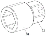
图8为本发明中旋具连接器的结构示意图。Fig. 8 is a schematic structural view of the screwdriver connector in the present invention.
图中:1-旋压组件、11-旋压板、12-旋压杆、13-旋压头、2-工作台、3-热弹组件、31-热弹板、32-发热球头、33-弹性复位件、34-安置孔、35-电热丝、36-导线、37-刚性导向柱、4-电源、41-调制器、5-旋具连接器、51-套筒、52-旋具接头、6-压合组件、61-压合板、62-螺栓、63-支撑板、7-待压板材。In the figure: 1-spinning assembly, 11-spinning plate, 12-spinning rod, 13-spinning head, 2-workbench, 3-thermal elastic assembly, 31-thermal elastic plate, 32-heating ball head, 33 -Elastic return part, 34-placement hole, 35-heating wire, 36-conductor, 37-rigid guide column, 4-power supply, 41-modulator, 5-screw connector, 51-sleeve, 52-screw Joint, 6-compression assembly, 61-compression plate, 62-bolt, 63-support plate, 7-plate to be pressed.
具体实施方式detailed description
下面结合附图对本发明的具体实施方式作进一步说明。在此需要说明的是,对于这些实施方式的说明用于帮助理解本发明,但并不构成对本发明的限定。此外,下面所描述的本发明各个实施方式中所涉及的技术特征只要彼此之间未构成冲突就可以相互组合。The specific embodiments of the present invention will be further described below in conjunction with the accompanying drawings. It should be noted here that the descriptions of these embodiments are used to help understand the present invention, but are not intended to limit the present invention. In addition, the technical features involved in the various embodiments of the present invention described below may be combined with each other as long as they do not constitute a conflict with each other.
需要说明的是,在本发明的描述中,术语“上”、“下”、“左”、“右”、“前”、“后”等指示的方位或位置关系为基于附图所示对本发明结构的说明,仅是为了便于描述本发明的简便,而不是指示或暗示所指的装置或元件必须具有特定的方位、以特定的方位构造和操作,因此不能理解为对本发明的限制。It should be noted that, in the description of the present invention, the orientation or positional relationship indicated by the terms "upper", "lower", "left", "right", "front", "back" etc. The description of the structure of the invention is only for the convenience of describing the invention, but does not indicate or imply that the device or element referred to must have a specific orientation, be constructed and operated in a specific orientation, and thus should not be construed as limiting the present invention.
对于本技术方案中的“第一”和“第二”,仅为对相同或相似结构,或者起相似功能的对应结构的称谓区分,不是对这些结构重要性的排列,也没有排序、或比较大小、或其他含义。For the "first" and "second" in this technical solution, it is only to distinguish the names of the same or similar structures, or the corresponding structures with similar functions, not to arrange the importance of these structures, nor to sort or compare them size, or other meanings.
另外,除非另有明确的规定和限定,术语“安装”、“连接”应做广义理解,例如,连接可以是固定连接,也可以是可拆卸连接,或一体地连接;可以是机械连接,也可以是电连接;可以是直接相连,也可以通过中间媒介间接相连,可以是两个结构内部的连通。对于本领域的普通技术人员而言,可以根据本发明的总体思路,联系本方案上下文具体情况理解上述术语在本发明中的具体含义。In addition, unless otherwise clearly specified and limited, the terms "installation" and "connection" should be interpreted in a broad sense, for example, the connection can be a fixed connection, a detachable connection, or an integral connection; it can be a mechanical connection, or It can be an electrical connection; it can be a direct connection, or an indirect connection through an intermediary, or an internal connection between two structures. Those of ordinary skill in the art can understand the specific meanings of the above terms in the present invention in accordance with the general idea of the present invention and in connection with the specific circumstances of the context of this solution.
实施例一Embodiment one
一种旋压渐进成型装置,如图1所示,包括旋压组件1、工作台2、热弹组件3和压合组件6。A spinning progressive forming device, as shown in FIG.
本实施例中,工作台2配置为铸铁制造的平板,由于铸铁具有吸收机器振动的能力,因此可提高金属板材成型加工的精度。In this embodiment, the
本实施例中,如图2-4所示,热弹组件3包括热弹板31以及多个发热球头32。热弹板31为平板,其放置或者固定在工作台2上,热弹板31的中部设置有热弹区域,上述的多个发热球头32则均匀分布在该热弹区域内,具体的是,在热弹区域上优选以均匀分布的方式布置多个弹性复位件33,每个弹性复位件33的顶端都安装一个发热球头32。In this embodiment, as shown in FIGS. 2-4 , the thermal
其中,配置弹性复位件33为呈竖直状布置的螺旋弹簧,另外在上述热弹区域中开设多个安置孔34以便于螺旋弹簧安置于其中,当然,螺旋弹簧还可以通过焊接或者粘接的方式固定在热弹板上。在另一个实施例中,还可以配置弹性复位件31为水平布置的弹片,该弹片呈弯曲的弧状结构,发热球头32固定在弹片上后同样可以获得竖直方向的弹性运动行程,从而具有与竖直布置的螺旋弹簧类似的作用和效果。Wherein, the
其中,配置发热球头32内部布置有电热丝35,电热丝35连接有铜质的导线36以便于接电,例如单芯铜导线;并进一步的配置发热球头32为空心结构,其内部抽真空,电热丝35位于其真空状态的空心结构内;当然在另一个实施例中,发热球头32还可以是实心结构,电热丝35一体成型在其内部。另外,优选配置导线36通过上述的安置孔34引出到热弹板31外部,例如,在热弹板31的侧壁上再开设多个水平设置的穿线孔,穿线孔与安置孔相连通即可确保导线36全程从热弹板31的内部布线,从而避免导线36缠绕以及干扰其他部件;而在另一个实施例中,还可直接在热弹板31的顶面布置导线36即可。Wherein, a
本实施例中,如图5所示,压合组件6包括两个相对布置且可拆卸连接的压合板61,压合板61的相对处分别设置有镂空孔,以便于将待压板材7夹设于两个压合板61之间的镂空孔边沿处后,待压板材7的顶面和底面均不被阻挡,例如,压合板61以及镂空孔均配置为矩形,且两者的各边分别互相平行。其中,压合组件6置于热弹组件3的上方,并且镂空孔正对热弹板31上的热弹区域。其中,压合组件6放置在热弹组件3上方后,被夹紧固定的待压板材7的底面与发热球头32相接触,其接触的形式可以是由发热球头32对待压板材形成重力支撑,从而使压合组件6整体悬空,或者,还可以是压合板61首先在重力作用与热弹板31相接触,进而促使待压板材7对发热球头32形成压迫,以上两种形式均可。In this embodiment, as shown in FIG. 5 , the
其中,上述的两个压合板61优选通过多个螺栓62可拆卸固定连接,或者还可以通过销或者榫卯结构可拆卸固定连接。Wherein, the above-mentioned two
本实施例中,如图6所示,旋压组件1包括旋压板11和多个旋压杆12。同样的,旋压板11的中部设置有旋压区域,旋压区域优选以均匀分布的方式开设有多个螺纹通孔,而上述的多个旋压杆12则螺纹连接在螺纹通孔中,同时,每个旋压杆12下端均设置有旋压头13。其中,旋压组件1使用时置于压合组件6的上方,并且旋压板11的旋压区域正对这压合板61上的镂空孔,从而使通过旋拧旋压板11后即可通过旋压头13对下方的待压板材进行挤压成型操作。In this embodiment, as shown in FIG. 6 , the spinning assembly 1 includes a spinning
另外,本实施例中,设置旋压杆12以及发热球头32分别呈矩阵状均匀分布在旋压区域和热弹区域内,其实现方式为首先使螺纹通孔和安置孔分别呈矩阵状均匀分布在旋压区域和热弹区域内,再为每个螺纹通孔和安置孔均对应配置一个旋压杆12以及发热球头32。当然,在实际使用时,可根据实际情况选择配置的旋压杆12、发热球头32的数量及其分布方式。In addition, in this embodiment, the spinning
本发明的工作使用原理是:首先将旋压组件1、固定有待压板材7的压合组件6、热弹组件3按照上述的方案组装好,并按照自下而上的顺序层叠在工作台2上,再将电源接入热弹组件3上的导线36,通过手动工具、电动工具或者数控机床等旋拧一个或者多个旋压杆12,同时向与被旋压位置对应处的发热球头32供电使其发热,即可对被旋压位置进行加热,在减少成形区域上材料屈服强度的同时,还能够减少残余应力、提高材料的成形极限,降低成形后板材的回弹效应;另外,弹性复位件33受压并存储弹力后,还可以在旋压头13移开后对板材起到局部动态支撑的作用。The working principle of the present invention is as follows: firstly assemble the spinning assembly 1, the
实施例二Embodiment two
其与实施例一的区别在于:本实施例中,设置热弹组件3还包括中空的刚性导向柱37,如图4所示,并且每个螺旋弹簧均配置有刚性导向柱37,刚性导向柱37穿设在螺旋弹簧内,即,刚性导向柱37也布置在安置孔34中,并且刚性导向柱37的顶端也固定连接在发热球头32上,从而在螺旋弹簧伸缩运动时对其起到导向和限制作用,防止螺旋弹簧因发生偏移或者倒伏而影响弹力效果。相应的,上述的导线36穿设在刚性导向柱37的中空结构内。The difference from Embodiment 1 is that in this embodiment, the
实施例三Embodiment three
其与实施例一的区别在于:本实施例中,如图5所示,设置压合组件6还包括支撑板63,支撑板63呈环形,支撑板63置于热弹板3的顶面并且支撑板63的边框环绕热弹区域布置,同时,支撑板63位于两个压合板61的下方,以便于通过支撑板63的边框对螺栓62提供支撑。The difference between it and Embodiment 1 is that in this embodiment, as shown in FIG. 5 , the
如此设置,使得通过支撑板63提高整体的稳定性。Such an arrangement enables the overall stability to be improved by the
另外,还可以在支撑板63的边框上开设螺纹孔,以便于螺栓62中的螺柱旋拧在其中,从而使压合组件6整体连接固定。In addition, threaded holes can also be provided on the frame of the
实施例四Embodiment four
其与实施例一的区别在于:本实施例中,如图1及图7所示,还包括电源4,电源4设置在工作台2上,且配置电源4为多路输出电源,例如多路输出开关电源,而上述的多个发热球头32则分别通过其上连接的导线36连接在多路输出电源的多个输出接头上。The difference from Embodiment 1 is that in this embodiment, as shown in Figure 1 and Figure 7, it also includes a power supply 4, which is arranged on the
同时,还包括调制器41,多路输出电源的每个输出接头上均设置有调制器41,以便于通过调制器41分别调制多路输出电源输出的各路电流的大小,从而单独地对每个发热球头32进行发热通断以及发热强度的调控。另外,调制器41在增加电抗的同时还起到保护电路的作用。At the same time, a
实施例五Embodiment five
其与实施例一的区别在于:本实施例中,配置旋压组件1还包括至少一个旋具连接器5,同时设置旋压杆12的上端横截面为非圆形,例如六角形,而旋具连接器5的下端设置有与旋压杆12的上端相适配的套筒51,旋具连接器5的上端设置有用于连接旋具的旋具接头52,例如旋具接头52为横截面为方形或者六角形的柱状接头,如图8所示。The difference between it and Embodiment 1 is that in this embodiment, the configuration spinning assembly 1 also includes at least one screw connector 5, and the upper end cross section of the spinning
如此设置,不但方便了对旋压杆12进行操作,而且当旋具连接器5配置有多个时,还能够同时进行多点旋压操作,例如通过多点渐进成形进行预成形,并在形成大致形状后,再采用单点渐进成形进行后续的精加工再次成形,从而能提高成形效率,也可避免多点成形在一些复杂局部位置成型精度不高的问题。Such setting not only facilitates the operation of the spinning
以上结合附图对本发明的实施方式作了详细说明,但本发明不限于所描述的实施方式。对于本领域的技术人员而言,在不脱离本发明原理和精神的情况下,对这些实施方式进行多种变化、修改、替换和变型,仍落入本发明的保护范围内。The embodiments of the present invention have been described in detail above with reference to the accompanying drawings, but the present invention is not limited to the described embodiments. For those skilled in the art, without departing from the principle and spirit of the present invention, various changes, modifications, substitutions and modifications to these embodiments still fall within the protection scope of the present invention.
Claims (10)
Priority Applications (2)
| Application Number | Priority Date | Filing Date | Title |
|---|---|---|---|
| CN202110728918.8A CN113399552B (en) | 2021-06-29 | 2021-06-29 | Spinning incremental forming device |
| AU2021104268A AU2021104268A4 (en) | 2021-06-29 | 2021-07-17 | Spinning incremental forming device |
Applications Claiming Priority (1)
| Application Number | Priority Date | Filing Date | Title |
|---|---|---|---|
| CN202110728918.8A CN113399552B (en) | 2021-06-29 | 2021-06-29 | Spinning incremental forming device |
Publications (2)
| Publication Number | Publication Date |
|---|---|
| CN113399552A CN113399552A (en) | 2021-09-17 |
| CN113399552B true CN113399552B (en) | 2023-01-17 |
Family
ID=77680301
Family Applications (1)
| Application Number | Title | Priority Date | Filing Date |
|---|---|---|---|
| CN202110728918.8A Active CN113399552B (en) | 2021-06-29 | 2021-06-29 | Spinning incremental forming device |
Country Status (2)
| Country | Link |
|---|---|
| CN (1) | CN113399552B (en) |
| AU (1) | AU2021104268A4 (en) |
Citations (8)
| Publication number | Priority date | Publication date | Assignee | Title |
|---|---|---|---|---|
| JP2006055871A (en) * | 2004-08-18 | 2006-03-02 | Honda Motor Co Ltd | Pre-forming method for superplastic forming plate |
| CN201214117Y (en) * | 2008-06-30 | 2009-04-01 | 南京航空航天大学 | Gradually forming pressure head of slab with controllable pressure and forming apparatus thereof |
| CN103317007A (en) * | 2013-06-10 | 2013-09-25 | 青岛理工大学 | Self-heating tool head for incremental forming |
| EP2891527A1 (en) * | 2014-01-06 | 2015-07-08 | dSPACE digital signal processing and control engineering GmbH | Bending device for Semiflex circuit boards |
| KR101606325B1 (en) * | 2015-08-27 | 2016-03-24 | 부산대학교 산학협력단 | Flexible Forming Apparatus using a local bending effect |
| CN105478539A (en) * | 2015-12-29 | 2016-04-13 | 哈尔滨工业大学(威海) | Plate multipoint progressive forming device |
| CN112474980A (en) * | 2020-11-10 | 2021-03-12 | 长沙超旋机械科技有限责任公司 | Uniform heating spinning device and spinning method for end socket piece |
| CN112792219A (en) * | 2021-01-29 | 2021-05-14 | 赵雪蕾 | Plate multipoint progressive forming numerical control supporting device and numerical control multipoint progressive forming method |
Family Cites Families (2)
| Publication number | Priority date | Publication date | Assignee | Title |
|---|---|---|---|---|
| US6668612B2 (en) * | 2002-02-21 | 2003-12-30 | General Motors Corporation | Device for holding a sheet metal blank in a forming press |
| US7984635B2 (en) * | 2005-04-22 | 2011-07-26 | K.U. Leuven Research & Development | Asymmetric incremental sheet forming system |
-
2021
- 2021-06-29 CN CN202110728918.8A patent/CN113399552B/en active Active
- 2021-07-17 AU AU2021104268A patent/AU2021104268A4/en not_active Ceased
Patent Citations (8)
| Publication number | Priority date | Publication date | Assignee | Title |
|---|---|---|---|---|
| JP2006055871A (en) * | 2004-08-18 | 2006-03-02 | Honda Motor Co Ltd | Pre-forming method for superplastic forming plate |
| CN201214117Y (en) * | 2008-06-30 | 2009-04-01 | 南京航空航天大学 | Gradually forming pressure head of slab with controllable pressure and forming apparatus thereof |
| CN103317007A (en) * | 2013-06-10 | 2013-09-25 | 青岛理工大学 | Self-heating tool head for incremental forming |
| EP2891527A1 (en) * | 2014-01-06 | 2015-07-08 | dSPACE digital signal processing and control engineering GmbH | Bending device for Semiflex circuit boards |
| KR101606325B1 (en) * | 2015-08-27 | 2016-03-24 | 부산대학교 산학협력단 | Flexible Forming Apparatus using a local bending effect |
| CN105478539A (en) * | 2015-12-29 | 2016-04-13 | 哈尔滨工业大学(威海) | Plate multipoint progressive forming device |
| CN112474980A (en) * | 2020-11-10 | 2021-03-12 | 长沙超旋机械科技有限责任公司 | Uniform heating spinning device and spinning method for end socket piece |
| CN112792219A (en) * | 2021-01-29 | 2021-05-14 | 赵雪蕾 | Plate multipoint progressive forming numerical control supporting device and numerical control multipoint progressive forming method |
Also Published As
| Publication number | Publication date |
|---|---|
| CN113399552A (en) | 2021-09-17 |
| AU2021104268A4 (en) | 2021-11-04 |
Similar Documents
| Publication | Publication Date | Title |
|---|---|---|
| CN213225216U (en) | Matrix type flexible clamp | |
| CN102773654A (en) | Vehicle body clamp | |
| CN202701814U (en) | U-shaped clamping tool | |
| CN207223271U (en) | Welding tool setup | |
| CN113399552B (en) | Spinning incremental forming device | |
| CN206296700U (en) | A kind of clamp for machining | |
| CN207824190U (en) | A quick-change tooling for laser welding of power battery modules | |
| CN203530381U (en) | Thermal treatment clamp of thin-walled circular part | |
| CN212207438U (en) | Clamp for clamping circuit board | |
| CN110972557B (en) | Frock clamp for vibration test bench | |
| CN201702536U (en) | Assembly-welding tooling of frame | |
| CN204339657U (en) | The assembled frock of suspension arm of lorry-mounted crane | |
| CN207825475U (en) | A kind of hot riveting fixture for LED module | |
| CN110961846A (en) | COS welding fixture for semiconductor laser | |
| CN207087216U (en) | A kind of tool for welding fixture | |
| CN105522046B (en) | Float rod type fuel-quantity transducer fly rod contact spring riveting forming jig | |
| CN214489339U (en) | High-precision multi-iron-sheet quick clamping and welding device | |
| CN205085278U (en) | Steel sheet bends with moulding -die and press | |
| CN206982044U (en) | A kind of copper coin nickel sheet welds universal fixture | |
| CN109094096A (en) | A kind of hydraulic device of mold manufacture | |
| CN209811557U (en) | Slender rod piece welding deformation-preventing tool | |
| CN208614117U (en) | Electric power electronic module weld mold | |
| CN107378349A (en) | Welding tool setup | |
| CN207464207U (en) | The universal combined fixture of die electrode processing | |
| CN206643477U (en) | A kind of automobile instrument soldering of printed boards common support equipment |
Legal Events
| Date | Code | Title | Description |
|---|---|---|---|
| PB01 | Publication | ||
| PB01 | Publication | ||
| SE01 | Entry into force of request for substantive examination | ||
| SE01 | Entry into force of request for substantive examination | ||
| GR01 | Patent grant | ||
| GR01 | Patent grant | ||
| TR01 | Transfer of patent right |
Effective date of registration: 20250829 Address after: No. 418 Beixin Road, Xinhe Town, Chongming District, Shanghai, 202156 Patentee after: SHANGHAI YONGTAI AUTO PARTS Co.,Ltd. Country or region after: China Address before: 201306 Shanghai City, Shanghai City, Pudong New Area Road No. 999 Patentee before: SHANGHAI OCEAN University Country or region before: China |
|
| TR01 | Transfer of patent right |