CN113398689A - A dust collection device for building engineering construction - Google Patents
A dust collection device for building engineering construction Download PDFInfo
- Publication number
- CN113398689A CN113398689A CN202110700171.5A CN202110700171A CN113398689A CN 113398689 A CN113398689 A CN 113398689A CN 202110700171 A CN202110700171 A CN 202110700171A CN 113398689 A CN113398689 A CN 113398689A
- Authority
- CN
- China
- Prior art keywords
- box
- fixedly connected
- air
- engineering construction
- box body
- Prior art date
- Legal status (The legal status is an assumption and is not a legal conclusion. Google has not performed a legal analysis and makes no representation as to the accuracy of the status listed.)
- Pending
Links
- 239000000428 dust Substances 0.000 title claims abstract description 37
- 238000010276 construction Methods 0.000 title claims abstract description 24
- 238000001914 filtration Methods 0.000 claims abstract description 17
- XLYOFNOQVPJJNP-UHFFFAOYSA-N water Substances O XLYOFNOQVPJJNP-UHFFFAOYSA-N 0.000 abstract description 17
- 230000000694 effects Effects 0.000 abstract description 2
- 238000000034 method Methods 0.000 description 5
- 230000001174 ascending effect Effects 0.000 description 1
- 230000009286 beneficial effect Effects 0.000 description 1
- 238000004140 cleaning Methods 0.000 description 1
- 238000005516 engineering process Methods 0.000 description 1
- 230000000630 rising effect Effects 0.000 description 1
- 238000000926 separation method Methods 0.000 description 1
- 238000005507 spraying Methods 0.000 description 1
Images

Classifications
-
- B—PERFORMING OPERATIONS; TRANSPORTING
- B01—PHYSICAL OR CHEMICAL PROCESSES OR APPARATUS IN GENERAL
- B01D—SEPARATION
- B01D47/00—Separating dispersed particles from gases, air or vapours by liquid as separating agent
- B01D47/02—Separating dispersed particles from gases, air or vapours by liquid as separating agent by passing the gas or air or vapour over or through a liquid bath
-
- B—PERFORMING OPERATIONS; TRANSPORTING
- B01—PHYSICAL OR CHEMICAL PROCESSES OR APPARATUS IN GENERAL
- B01D—SEPARATION
- B01D29/00—Filters with filtering elements stationary during filtration, e.g. pressure or suction filters, not covered by groups B01D24/00 - B01D27/00; Filtering elements therefor
- B01D29/01—Filters with filtering elements stationary during filtration, e.g. pressure or suction filters, not covered by groups B01D24/00 - B01D27/00; Filtering elements therefor with flat filtering elements
- B01D29/03—Filters with filtering elements stationary during filtration, e.g. pressure or suction filters, not covered by groups B01D24/00 - B01D27/00; Filtering elements therefor with flat filtering elements self-supporting
-
- B—PERFORMING OPERATIONS; TRANSPORTING
- B01—PHYSICAL OR CHEMICAL PROCESSES OR APPARATUS IN GENERAL
- B01D—SEPARATION
- B01D29/00—Filters with filtering elements stationary during filtration, e.g. pressure or suction filters, not covered by groups B01D24/00 - B01D27/00; Filtering elements therefor
- B01D29/96—Filters with filtering elements stationary during filtration, e.g. pressure or suction filters, not covered by groups B01D24/00 - B01D27/00; Filtering elements therefor in which the filtering elements are moved between filtering operations; Particular measures for removing or replacing the filtering elements; Transport systems for filters
-
- B—PERFORMING OPERATIONS; TRANSPORTING
- B08—CLEANING
- B08B—CLEANING IN GENERAL; PREVENTION OF FOULING IN GENERAL
- B08B15/00—Preventing escape of dirt or fumes from the area where they are produced; Collecting or removing dirt or fumes from that area
- B08B15/04—Preventing escape of dirt or fumes from the area where they are produced; Collecting or removing dirt or fumes from that area from a small area, e.g. a tool
Abstract
The invention discloses a dust collecting device for constructional engineering construction, which relates to the field of engineering construction and comprises a box body, wherein a box cover is arranged at the upper end of the box body in a matching manner, a switch device is arranged between the box body and the box cover, a filtering device is arranged in the box body and comprises a filtering frame, the outer side wall of the filtering frame is in sliding connection with the inner side wall of the box body, a filtering net is arranged in the filtering frame, the switch device comprises a forward and reverse rotating motor, the lower end of the forward and reverse rotating motor is fixedly connected with a supporting base, and the upper surface of the supporting base is fixedly connected with the lower surface of the box body. The dust collecting device for the construction of the constructional engineering can effectively save water resources, has an excellent dust collecting effect, is easy to replace a filter screen, is easy to open a box body, is convenient to overhaul and clean the interior of the box body, and is simple to operate.
Description
Technical Field
The invention relates to the field of engineering construction, in particular to a dust collecting device for constructional engineering construction.
Background
With the continuous development of China, various construction projects appear, a large amount of dust is generated in the project construction process, and the dust needs to be treated in the project construction process in order to reduce the pollution of the dust to air and the damage of the dust to the bodies of construction workers.
The processing mode of dust generally all carries out the dust fall through spraying a large amount of water in the modern work progress, and a large amount of water resources can be wasted to the dust fall like this, and in addition, current dust disposal equipment structure is comparatively complicated, and inside is difficult to open overhauls and washs, and for this reason, we propose the dust collection device who is used for the building engineering construction.
Disclosure of Invention
The invention aims to provide a dust collecting device for constructional engineering construction, which can solve the problems that the existing dust removing device in the engineering construction provided by the background technology seriously wastes water resources and is inconvenient for cleaning equipment.
In order to achieve the purpose, the invention provides the following technical scheme: a dust collection device for building engineering construction, the power distribution box comprises a box body, the upper end cooperation of box is provided with the case lid, be provided with switching device between box and the case lid, the inside filter equipment that is provided with of box, filter equipment is including crossing the filter frame, the lateral wall that crosses the filter frame and the inside wall sliding connection of box, be provided with the filter screen in the filter frame, the right side fixedly connected with air-supply line of case lid, be connected with the draught fan on the air-supply line, the bottom of box is connected with the drain pipe, the drain pipe is located the lower extreme of filter screen.
Further, switching device is including just reversing motor, just reversing motor's lower extreme fixedly connected with supports the base, the upper surface of support base and the lower fixed surface of box are connected, both sides fixedly connected with connecting block around the case lid is located threaded connection has the threaded rod on the connecting block of case lid front end, the lower extreme of threaded rod and just reversing motor's output shaft fixed connection are located sliding connection has the gag lever post on the connecting block of case lid rear end, the bottom of gag lever post and the upper surface fixed connection who supports the base.
Further, equal fixedly connected with fixed block on the inside wall of both ends around the filter frame, the draw-in groove has been seted up to the inboard of fixed block, logical groove has been seted up in the left side of filter frame, set up flutedly on the right-hand member inside wall of filter frame, the filter screen sets up in draw-in groove, logical groove and recess.
Further, the upper end of fixed block has seted up the bolt hole, bolt hole on the fixed block and the draw-in groove on the fixed block communicate each other, bolt hole female connection on the fixed block has the shank of bolt, the upper end fixedly connected with axle sleeve of shank of bolt, the upper end swivelling joint of axle sleeve has the connecting rod, the top of connecting rod and the lower fixed surface of case lid are connected.
Further, the left side fixedly connected with of case lid goes out the tuber pipe, it is connected with the air-blower on the tuber pipe to go out, the equal fixed mounting of draught fan and air-blower is on the case lid, the length that the air-supply line is located the box is greater than the length that the tuber pipe is located the box, the air-supply line is located one of the box outside and serves and be connected with the cover body.
Further, be connected with the valve on the drain pipe, fixed mounting has control panel on the lateral wall of box, control panel's output and draught fan, air-blower and the input electric connection of just reversing motor.
Compared with the prior art, the invention has the beneficial effects that:
1. when the device is used, enough water is added into the box body, so that the water submerges the air inlet pipe and does not submerge the air outlet pipe, the draught fan is started, gas with dust enters the box body, the dust is collected through the water in the box body, the purified gas is discharged through the air outlet pipe through the air blower, the water has a good dust filtering effect on a construction site, and the dust collection work is completed; through being provided with the filter screen, conveniently carry out filtering operation to the water that absorbs the dust, filterable water passes through the drain pipe discharge, can be used for next time dust to collect the operation, the water economy resource.
2. This device is rotatory through positive and negative motor drive threaded rod, threaded rod and connecting block threaded connection, and sliding connection has the gag lever post on the connecting block of case lid rear side, and the rotatory in-process of motor that just reverses can drive the case lid and rise, and the inside exposure of box is convenient overhauls the box inside.
3. This device case lid can drive the filter frame when rising and rise, filter and be connected through connecting rod and shank of bolt between frame and the case lid, the rotation shank of bolt can be accomplished and filter being connected or separating between frame and the case lid, the rotation shank of bolt can make the shank of bolt pass the bolt hole on the fixed block simultaneously, make the shank of bolt live the upper surface of filter screen, can fix the filter screen, it only needs the shank of bolt unscrewing to need to change the filter screen, can take out the filter screen in the filter frame through leading to the groove, change the filter screen, easy operation is swift.
Drawings
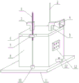
Fig. 1 is a schematic view of the overall structure of the present invention.
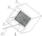
Fig. 2 is a schematic view of the internal structure of the case of the present invention.
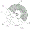
Fig. 3 is an enlarged view of the invention at a in fig. 3.
Fig. 4 is a partial cross-sectional view of the case and cover of the present invention.
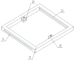
Fig. 5 is a schematic structural view of the frame of the present invention.
In the figure: 1. a threaded rod; 2. a limiting rod; 3. an air outlet pipe; 4. a cover body; 5. an air inlet pipe; 6. a box cover; 7. connecting blocks; 8. a box body; 9. an induced draft fan; 10. a positive and negative rotation motor; 11. a support base; 12. a control panel; 13. a connecting rod; 14. a filter screen; 15. a filter frame; 16. a shaft sleeve; 17. a bolt shank; 18. a fixed block; 19. a through groove; 20. a card slot; 21. a groove; 22. a drain pipe; 23. a blower.
Detailed Description
The technical solutions in the embodiments of the present invention will be clearly and completely described below with reference to the drawings in the embodiments of the present invention, and it is obvious that the described embodiments are only a part of the embodiments of the present invention, and not all of the embodiments. All other embodiments, which can be derived by a person skilled in the art from the embodiments given herein without making any creative effort, shall fall within the protection scope of the present invention.
Referring to fig. 1-5, a dust collecting device for construction engineering construction includes a box body 8, a box cover 6 is cooperatively arranged at the upper end of the box body 8, a switch device is arranged between the box body 8 and the box cover 6, a filtering device is arranged inside the box body 8, the filtering device includes a filtering frame 15, the outer side wall of the filtering frame 15 is slidably connected with the inner side wall of the box body 8, a filtering net 14 is arranged in the filtering frame 15, an air inlet pipe 5 is fixedly connected to the right side of the box cover 6, an induced draft fan 9 is connected to the air inlet pipe 5, a drain pipe 22 is connected to the bottom end of the box body 8, and the drain pipe 22 is located at the lower end of the filtering net 14.
Switching device includes positive reverse motor 10, the lower extreme fixedly connected with of positive reverse motor 10 supports base 11, the upper surface of support base 11 is connected with the lower fixed surface of box 8, both sides fixedly connected with connecting block 7 around case lid 6, threaded connection has threaded rod 1 on the connecting block 7 that is located the 6 front ends of case lid, the lower extreme of threaded rod 1 and the output shaft fixed connection of positive reverse motor 10, sliding connection has gag lever post 2 on the connecting block 7 that is located the 6 rear ends of case lid, the bottom of gag lever post 2 and the upper surface fixed connection who supports base 11, it is rotatory through positive reverse motor 10 drive threaded rod 1, threaded rod 1 and connecting block 7 threaded connection, and sliding connection has gag lever post 2 on the connecting block 7 of case lid 6 rear side, can drive case lid 6 and go up and down when the in-process of positive reverse motor 10 positive reverse.
All fixedly connected with fixed block 18 on the inside wall of filter frame 15 front and back both ends, draw-in groove 20 has been seted up to the inboard of fixed block 18, and logical groove 19 has been seted up on the left side of filter frame 15, sets up flutedly 21 on the right-hand member inside wall of filter frame 15, and filter screen 14 sets up in draw-in groove 20, logical groove 19 and recess 21.
The upper end of fixed block 18 has seted up the bolt hole, and the bolt hole on the fixed block 18 communicates with draw-in groove 20 on the fixed block 18 each other, and threaded connection has bolt bar 17 in the bolt hole on the fixed block 18, and the upper end fixedly connected with axle sleeve 16 of bolt bar 17, the upper end swivelling joint of axle sleeve 16 have connecting rod 13, and the top of connecting rod 13 is connected with the lower fixed surface of case lid 6.
The left side fixedly connected with of case lid 6 goes out tuber pipe 3, goes out to be connected with air-blower 23 on the tuber pipe 3, and the equal fixed mounting of draught fan 9 and air-blower 23 is on case lid 6, and the length that air-supply line 5 is located box 8 is greater than the length that air-supply line 3 is located box 8, and one of the air-supply line 5 is located the box 8 outside serves and is connected with cover body 4, and cover body 4 can increase the area of induced air, improves the efficiency of collecting the dust.
The drain pipe 22 is connected with a valve, the outer side wall of the box body 8 is fixedly provided with a control panel 12, and the output end of the control panel 12 is electrically connected with the input ends of the draught fan 9, the air blower 23 and the positive and negative rotating motor 10.
The invention has the structural characteristics and the working principle that: when the device is used, the draught fan 9, the blower 23, the positive and negative rotation motor 10 and the control panel 12 in the device are electrified, the draught fan 9, the blower 23 and the positive and negative rotation motor 10 are controlled to work through the control panel 12, before the device is used, enough water is firstly added into the box body 8 to ensure that the water submerges the air inlet pipe 5 and does not submerge the air outlet pipe 3, the draught fan 9 is started to ensure that gas with dust enters the box body 8, the dust is collected through the water in the box body 8, the purified gas is discharged through the air outlet pipe 3 through the blower 23 to finish the collection work of the dust, the device is provided with the filter screen 14 to facilitate the filtration operation of the water absorbing the dust, the filtered water is discharged through the drain pipe 22 and can be used for the next dust collection operation, the water resource is saved, the threaded rod 1 is driven to rotate through the positive and negative rotation motor 10, and the threaded rod 1 is in threaded connection with the connecting block 7, and the connecting block 7 at the rear side of the box cover 6 is connected with the limiting rod 2 in a sliding manner, the box cover 6 can be driven to ascend in the rotating process of the forward and reverse rotating motor 10, the interior of the box body 8 is convenient to overhaul, the box cover 6 can drive the filter frame 15 to ascend while ascending, the filter frame 15 and the box cover 6 are connected through the connecting rod 13 and the bolt rod 17, the bolt rod 17 can be rotated to complete the connection or separation between the filter frame 15 and the box cover 6, meanwhile, the bolt rod 17 can be rotated to enable the bolt rod 17 to penetrate through a bolt hole in the fixing block 18, the bolt rod 17 presses the upper surface of the filter screen 14, the filter screen 14 can be fixed, the filter screen 14 needs to be replaced, the bolt rod 17 only needs to be unscrewed, the filter screen 14 in the filter frame 15 can be drawn out through the through groove 19, the replacement operation is completed, and the operation is simple and rapid.
It will be evident to those skilled in the art that the invention is not limited to the details of the foregoing illustrative embodiments, and that the present invention may be embodied in other specific forms without departing from the spirit or essential attributes thereof. The present embodiments are therefore to be considered in all respects as illustrative and not restrictive, the scope of the invention being indicated by the appended claims rather than by the foregoing description, and all changes which come within the meaning and range of equivalency of the claims are therefore intended to be embraced therein. Any reference sign in a claim should not be construed as limiting the claim concerned.
Furthermore, it should be understood that although the present description refers to embodiments, not every embodiment may contain only a single embodiment, and such description is for clarity only, and those skilled in the art should integrate the description, and the embodiments may be combined as appropriate to form other embodiments understood by those skilled in the art.
Claims (6)
1. A dust collection device for building engineering construction, including box (8), its characterized in that, the upper end cooperation of box (8) is provided with case lid (6), be provided with switching device between box (8) and case lid (6), box (8) inside is provided with filter equipment, filter equipment is including filtering frame (15), filter the lateral wall of frame (15) and the inside wall sliding connection of box (8), be provided with filter screen (14) in filtering frame (15), the right side fixedly connected with air-supply line (5) of case lid (6), be connected with draught fan (9) on air-supply line (5), the bottom of box (8) is connected with drain pipe (22), drain pipe (22) are located the lower extreme of filter screen (14).
2. The dust collecting device for building engineering construction according to claim 1, wherein the switch device comprises a forward and reverse rotation motor (10), a support base (11) is fixedly connected to the lower end of the forward and reverse rotation motor (10), the upper surface of the support base (11) is fixedly connected to the lower surface of the box body (8), connecting blocks (7) are fixedly connected to the front side and the rear side of the box cover (6), a threaded rod (1) is connected to the connecting block (7) on the front side of the box cover (6) in a threaded manner, the lower end of the threaded rod (1) is fixedly connected to the output shaft of the forward and reverse rotation motor (10) and is connected to the connecting block (7) on the rear side of the box cover (6) in a sliding manner, and a limiting rod (2) is connected to the bottom of the limiting rod (2) and the upper surface of the support base (11) in a fixed manner.
3. The dust collecting device for building engineering construction according to claim 1, wherein the filter frame (15) is fixedly connected with fixing blocks (18) on the inner side walls of the front end and the rear end of the filter frame, a clamping groove (20) is formed in the inner side of each fixing block (18), a through groove (19) is formed in the left side of the filter frame (15), a groove (21) is formed in the inner side wall of the right end of the filter frame (15), and the filter screen (14) is arranged in the clamping groove (20), the through groove (19) and the groove (21).
4. The dust collecting device for constructional engineering construction as claimed in claim 3, wherein a bolt hole is formed in the upper end of the fixing block (18), the bolt hole in the fixing block (18) is communicated with a clamping groove (20) in the fixing block (18), a bolt rod (17) is connected in the bolt hole in the fixing block (18) in a threaded manner, a shaft sleeve (16) is fixedly connected to the upper end of the bolt rod (17), a connecting rod (13) is rotatably connected to the upper end of the shaft sleeve (16), and the top end of the connecting rod (13) is fixedly connected with the lower surface of the box cover (6).
5. The dust collecting device for building engineering construction according to claim 1, characterized in that, the left side fixedly connected with of case lid (6) goes out tuber pipe (3), be connected with air-blower (23) on going out tuber pipe (3), the equal fixed mounting of draught fan (9) and air-blower (23) is on case lid (6), the length that air-supply line (5) are located box (8) is greater than the length that air-supply line (3) are located box (8), one end that air-supply line (5) are located the box (8) outside is connected with the cover body (4).
6. The dust collecting device for the constructional engineering construction according to claim 1, wherein the drain pipe (22) is connected with a valve, the outer side wall of the box body (8) is fixedly provided with a control panel (12), and the output end of the control panel (12) is electrically connected with the input ends of the induced draft fan (9), the air blower (23) and the positive and negative rotation motor (10).
Priority Applications (1)
| Application Number | Priority Date | Filing Date | Title |
|---|---|---|---|
| CN202110700171.5A CN113398689A (en) | 2021-06-23 | 2021-06-23 | A dust collection device for building engineering construction |
Applications Claiming Priority (1)
| Application Number | Priority Date | Filing Date | Title |
|---|---|---|---|
| CN202110700171.5A CN113398689A (en) | 2021-06-23 | 2021-06-23 | A dust collection device for building engineering construction |
Publications (1)
| Publication Number | Publication Date |
|---|---|
| CN113398689A true CN113398689A (en) | 2021-09-17 |
Family
ID=77682693
Family Applications (1)
| Application Number | Title | Priority Date | Filing Date |
|---|---|---|---|
| CN202110700171.5A Pending CN113398689A (en) | 2021-06-23 | 2021-06-23 | A dust collection device for building engineering construction |
Country Status (1)
| Country | Link |
|---|---|
| CN (1) | CN113398689A (en) |
Cited By (1)
| Publication number | Priority date | Publication date | Assignee | Title |
|---|---|---|---|---|
| CN114225596A (en) * | 2021-12-31 | 2022-03-25 | 中海外交通建设有限公司 | A dust collection device for building engineering construction |
Citations (3)
| Publication number | Priority date | Publication date | Assignee | Title |
|---|---|---|---|---|
| JP2014237108A (en) * | 2013-06-10 | 2014-12-18 | 仁孝 福井 | Dust collection method and dust collection apparatus |
| CN210171078U (en) * | 2019-06-24 | 2020-03-24 | 天津市四维康环保科技发展有限公司 | Smoke and dust air pollution processing apparatus |
| CN212998623U (en) * | 2020-07-06 | 2021-04-20 | 孙仁芳 | Sewage treatment tank convenient for mounting filter screen |
-
2021
- 2021-06-23 CN CN202110700171.5A patent/CN113398689A/en active Pending
Patent Citations (3)
| Publication number | Priority date | Publication date | Assignee | Title |
|---|---|---|---|---|
| JP2014237108A (en) * | 2013-06-10 | 2014-12-18 | 仁孝 福井 | Dust collection method and dust collection apparatus |
| CN210171078U (en) * | 2019-06-24 | 2020-03-24 | 天津市四维康环保科技发展有限公司 | Smoke and dust air pollution processing apparatus |
| CN212998623U (en) * | 2020-07-06 | 2021-04-20 | 孙仁芳 | Sewage treatment tank convenient for mounting filter screen |
Cited By (2)
| Publication number | Priority date | Publication date | Assignee | Title |
|---|---|---|---|---|
| CN114225596A (en) * | 2021-12-31 | 2022-03-25 | 中海外交通建设有限公司 | A dust collection device for building engineering construction |
| CN114225596B (en) * | 2021-12-31 | 2023-03-10 | 中海外交通建设有限公司 | A dust collection device for building engineering construction |
Similar Documents
| Publication | Publication Date | Title |
|---|---|---|
| CN103479305B (en) | A kind of water circulation ground washing vehicle | |
| CN205975797U (en) | Rainwater collecting and processing device | |
| CN113398689A (en) | A dust collection device for building engineering construction | |
| CN210938332U (en) | Digit control machine tool dust collector | |
| CN210251656U (en) | Dust removal environmental protection equipment for sheet metal working | |
| CN210103656U (en) | Sewage purification equipment | |
| CN108483569B (en) | Sewage treatment pond mud sediment collection limit remove device that floats | |
| CN113521845A (en) | Sponge urban rainwater treatment and recycling integrated equipment and treatment method thereof | |
| CN111577372B (en) | Vehicle-mounted filter cylinder dust removal equipment for tunnel | |
| CN216694532U (en) | Efficient sand prevention and dust removal device for cooling tower | |
| CN216934889U (en) | Remove case room convenient to domestic sewage discharges | |
| CN220513538U (en) | Sundry filter for recycling printing and dyeing wastewater | |
| CN219052069U (en) | Sand screening machine | |
| CN218188189U (en) | Energy-concerving and environment-protective multi-functional municipal sewage treatment plant | |
| CN216170791U (en) | A air purification device that is used for intelligent building that filter effect is good | |
| CN216244753U (en) | Indoor air purification device | |
| CN213119228U (en) | Environment-friendly oil smoke separation purifies lampblack absorber | |
| CN216171069U (en) | Dust fall equipment for building engineering | |
| CN212915002U (en) | Dust collection device that building engineering construction was used | |
| CN213192906U (en) | High-efficient filterable air tank pulse dust collector | |
| CN205116077U (en) | Multi -functional road surface cleaner | |
| CN215142765U (en) | Rice belt cleaning device is used in miso production | |
| CN220779459U (en) | Dust removing mechanism for cotton mixing box | |
| CN212358166U (en) | Road surface accumulated dust removing device | |
| CN212919604U (en) | Cutting device of environmental protection for building engineering |
Legal Events
| Date | Code | Title | Description |
|---|---|---|---|
| PB01 | Publication | ||
| PB01 | Publication | ||
| SE01 | Entry into force of request for substantive examination | ||
| SE01 | Entry into force of request for substantive examination | ||
| RJ01 | Rejection of invention patent application after publication | ||
| RJ01 | Rejection of invention patent application after publication |
Application publication date: 20210917 |