CN113354746B - Starch dehydration equipment - Google Patents
Starch dehydration equipment Download PDFInfo
- Publication number
- CN113354746B CN113354746B CN202110840839.6A CN202110840839A CN113354746B CN 113354746 B CN113354746 B CN 113354746B CN 202110840839 A CN202110840839 A CN 202110840839A CN 113354746 B CN113354746 B CN 113354746B
- Authority
- CN
- China
- Prior art keywords
- frame
- driving
- component
- fit
- rotating shaft
- Prior art date
- Legal status (The legal status is an assumption and is not a legal conclusion. Google has not performed a legal analysis and makes no representation as to the accuracy of the status listed.)
- Active
Links
Images


Classifications
-
- C—CHEMISTRY; METALLURGY
- C08—ORGANIC MACROMOLECULAR COMPOUNDS; THEIR PREPARATION OR CHEMICAL WORKING-UP; COMPOSITIONS BASED THEREON
- C08B—POLYSACCHARIDES; DERIVATIVES THEREOF
- C08B30/00—Preparation of starch, degraded or non-chemically modified starch, amylose, or amylopectin
- C08B30/06—Drying; Forming
Abstract
The invention discloses a starch dehydration device, which belongs to the technical field of starch dehydration and comprises an operation table and a dehydration device, wherein the operation table is placed on the ground, a sandwich plate is arranged on the operation table, the dehydration device is arranged at the top of the operation table and is in rotating fit with the operation table, the dehydration device comprises a driving assembly, an adjusting assembly, a dehydration assembly and a scraping assembly, the driving assembly is arranged on the side wall of the operation table, the adjusting assembly is arranged at the top of the sandwich plate, the dehydration assembly is arranged on the driving assembly, and the scraping assembly is arranged on the dehydration assembly and is in sliding fit with the dehydration assembly. The situation that starch is stuck on the elastic filter cloth to cause difficulty in collection is prevented.
Description
Technical Field
The invention discloses starch dehydration equipment, and belongs to the technical field of starch dehydration.
Background
Starch is usually made from potatoes such as potatoes and cassava, and in the process of preparing starch, part of the process produces starch as a viscous liquid which needs to be dehydrated to form a powdery starch form, thus requiring the use of a dehydrator.
The invention discloses a granular starch vacuum dehydrator, which belongs to the technical field of starch dehydrating equipment and comprises a vacuum drum, wherein the lower part of the vacuum drum is positioned in a starch liquid storage tank, the outer side wall of the vacuum drum is provided with a filter screen, the outer side of the filter screen is coated with filter cloth, one end of a rotating shaft of the vacuum drum is provided with a vacuum separation disc, a plurality of vacuum holes are formed in a half disc of the vacuum separation disc close to the vacuum drum along the circumferential direction, the vacuum holes are respectively connected with a vacuum tube, and the other end of the vacuum tube is connected to the filter screen. The method utilizes a vacuum pump and a vacuum roller to carry out three working stages of adsorption, dehydration and separation, removes 40-42% of moisture from starch liquid with the concentration of 17-20 be, and prepares granular starch with the moisture of less than 18% through a natural drying process, and has the advantages of low production cost, high yield and good economic benefit.
However, the invention has the following defects that the filter screen cannot be disassembled, replaced and cleaned, the starch dehydration efficiency is reduced after the filter screen is used for a long time, and the filter screen cannot be supported flat in the working process, so that the phenomenon of wrinkling is caused, and the starch dehydration operation is influenced.
Disclosure of Invention
The embodiment of the invention provides starch dehydration equipment, which aims to solve the technical problems that in the prior art, the starch dehydration efficiency is reduced after a filter screen is used for a long time, and the starch dehydration operation is influenced by the phenomenon that the filter screen cannot be flattened and wrinkles appear in the working process.
The embodiment of the invention adopts the following technical scheme: the utility model provides a starch dewatering equipment includes the operation panel, the operation panel is placed in subaerial, be equipped with the sandwich panel on the operation panel, still include dewatering device, dewatering device install at the top of operation panel and with operation panel normal running fit, dewatering device includes drive assembly, adjusting part, dehydration subassembly and scrapes the material subassembly, drive assembly install on the lateral wall of operation panel and with operation panel normal running fit, adjusting part install at the top of sandwich panel and with drive assembly normal running fit, dehydration subassembly install on drive assembly and with drive assembly normal running fit, scrape the material subassembly install on the dehydration subassembly and with dehydration subassembly sliding fit.
Further, the driving assembly comprises a driving motor, a first bevel gear, a second bevel gear and a driving rod, the driving motor is fixedly installed on the inner wall of the operating platform, the first bevel gear is installed on a main shaft of the driving motor and is in transmission fit with the main shaft of the driving motor, the driving rod is installed on the operating platform and is in running fit with the operating platform, a gear shaft is arranged on the driving rod, the first bevel gear is meshed with the second bevel gear, a baffle is arranged at the bottom of the driving rod, the second bevel gear is located at the bottom of the operating platform and is in running fit with the operating platform, the second bevel gear is located at the lower part of the gear shaft, a tooth groove meshed with the second bevel gear is formed in the side wall of the second bevel gear, the tooth groove is in sliding fit with the gear shaft, and the driving rod can slide up and down in the axis direction of the second bevel gear.
Further, the adjusting part includes driving electric jar, alignment jig, locating piece and axis of rotation, the top at the intermediate layer board is installed to the driving electric jar, the one end of alignment jig is installed on the stroke slider of driving electric jar, be equipped with the slider on the alignment jig, locating piece fixed mounting is at the top of intermediate layer board, slider and locating piece sliding fit on the alignment jig, the axis of rotation cover establish on the actuating lever and with actuating lever normal running fit, the fixed contact block that is provided with on the actuating lever, the axis of rotation is located between two conflict blocks, the one end and the axis of rotation fixed connection of alignment jig.
Further, frame, top cap, support frame, articulated piece, link and two compression rollers are established including the cover to the dehydration subassembly, the cover establish the frame install on the operation panel and with operation panel normal running fit, the cover establish the frame with gear shaft meshing and with gear shaft sliding fit, the fixed ball that is provided with in top of actuating lever, the top cap install on fixed ball and with fixed ball normal running fit, the bilateral symmetry of top cap is provided with the fixed block, support frame fixed mounting establishes on the frame at the cover, be equipped with the draw-in groove on the support frame, one of them draw-in groove sliding fit on fixed block and the support frame, the one end and the articulated cooperation of another fixed block of articulated piece, the articulated other end that sets up at articulated piece of link, the link establishes frame sliding fit with the cover, two the compression roller rotates respectively and sets up on support frame and cover establish the frame.
Further, scrape the material subassembly and include the movable plate, promote electric jar, connecting seat, scrape the flitch, receive workbin and two electric jars of work, the movable plate install on the connecting seat and with connecting seat sliding fit, promote electric jar fixed mounting on the lateral wall of connecting seat, the stroke slider that promotes electric jar is connected with the movable plate, connecting seat fixed mounting is in the bottom of movable plate, two the articulated setting on the connecting seat of work electric jar symmetry, it articulates the setting on the connecting seat to scrape the flitch, scrape the articulated setting of stroke slider of flitch and two electric jars of work, receive the workbin and install the top at the operation panel.
Further, still be equipped with filter equipment on the operation panel, the top of operation panel is equipped with the filter-tank, filter equipment installs in the filter-tank on the operation panel and is located dewatering device's below, filter equipment is including changing subassembly and filtering component, change the top that the subassembly was installed at the filter-tank, filtering component installs on changing the subassembly.
Further, the replacing component comprises a supporting sleeve frame, a rotary handle, elastic filter cloth and a replacing part, the replacing part is provided with six groups, the six groups of replacing parts are identical in structure and are arranged on the filter tank in a circumferential mode, the six groups of replacing parts respectively comprise a hydraulic telescopic rod, a clamping frame, a rotating shaft, a first hinging frame and a second hinging frame, the hydraulic telescopic rod is arranged at the bottom of the filter tank, the clamping frame is arranged at the top of the hydraulic telescopic rod, the rotating shaft is arranged on the clamping frame and is in rotating fit with the clamping frame, the first hinging frame and the second hinging frame are symmetrically hinged on the rotating shaft, one first hinging frame on the rotating shaft and the adjacent second hinging frame on the rotating shaft are fixedly connected through a connecting block, the supporting sleeve frame is arranged on the rotating shaft and is in rotating fit with the rotating shaft, and the rotary handle is fixedly connected with one of the rotating shafts on the replacing part, the elastic filter cloth is detachably connected to the support sleeve frame and the connecting block.
Further, the filter assembly comprises a filter plate, a connecting pipe and a collecting box, the filter plate is fixedly arranged on the side walls of the clamping frames on the six groups of replacing parts, a plurality of filter holes are formed in the filter plate, drain holes are formed in the filter tank, the collecting box is arranged at the top of the sandwich plate, and two ends of the connecting pipe are respectively connected with the drain holes and the collecting box.
The embodiment of the invention adopts at least one technical scheme which can achieve the following beneficial effects:
when the driving motor drives the driving rod to rotate, the gear shaft on the driving rod drives the sleeve frame to rotate, the sleeve frame rotates to enable the two compression rollers to press and squeeze the starch which is not dehydrated on the filtering device, the starch is pressed back and forth through the two compression rollers, most of moisture in the starch can be effectively squeezed and discharged, the starch dehydration efficiency is improved, the moisture residual quantity in the starch is reduced, after the starch is dehydrated, the driving electric cylinder drives the driving rod to move, the fixing ball on the driving rod pushes against the top cover to enable the top cover to deflect, the top cover deflects to enable the sliding groove of one fixing block on the supporting frame to slide, the other fixing block drives the hinge block to move, the hinge block drives the connecting frame to move downwards on the sleeve frame, the scraping component is enabled to be tightly attached to the elastic filtering cloth, the starch which is dehydrated by the elastic filtering cloth is scraped through the rotation matching of the sleeve frame, the collection efficiency of starch is improved, and starch is prevented from being stuck on the elastic filter cloth to cause difficulty in collection.
And secondly, when the scraping component scrapes starch to the scraping plate under the matching of the dehydration component, the electric cylinder is pushed to drive the movable plate to move to the top of the material receiving box, the working electric cylinder drives the scraping plate to move downwards on the connecting seat, the starch on the scraping plate is poured into the material receiving box to complete the starch receiving operation, and the starch collecting work efficiency is improved.
Thirdly, after the starch is dehydrated, the hydraulic telescopic rod on the replacing part drives the clamping frame to move downwards, so that the two compression rollers can not block the detachment of the elastic filter cloth, an operator drives one rotating shaft to rotate by driving the rotating handle, the rotating shaft rotates to drive the first hinge frame and the second hinge frame to move and unfold, the first hinge frame and the second hinge frame are opened through the connecting block and can drive the adjacent first hinge frame and the second hinge frame to move and unfold so that the adjacent rotating shaft rotates to enable the six replacing parts to rotate, the elastic filter cloth connected to the connecting block and the supporting sleeve frame is turned outwards, the operator can replace and clean the elastic filter cloth after the starch is dehydrated conveniently, the working efficiency of the starch dehydration is improved, the elastic filter cloth is connected to the supporting sleeve frame and the connecting block, after the operator installs the elastic filter cloth, the rotary handle is driven to tighten the elastic filter cloth on the support sleeve frame and the connecting block, so that the elastic filter cloth is not wrinkled to influence the dehydration operation of starch.
Drawings
The accompanying drawings, which are included to provide a further understanding of the invention and are incorporated in and constitute a part of this specification, illustrate embodiments of the invention and together with the description serve to explain the invention and not to limit the invention. In the drawings:
FIG. 1 is a schematic perspective view of the present invention;
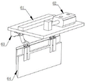
FIG. 2 is a schematic perspective view of the dehydration apparatus of the present invention;
FIG. 3 is a schematic view of a partial perspective structure of the dehydration apparatus of the present invention;
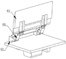
FIG. 4 is a schematic perspective view of a dewatering assembly of the present invention;
FIG. 5 is a schematic view of a first perspective structure of the scraping assembly of the present invention;
FIG. 6 is a schematic diagram of a second perspective view of the scraping assembly of the present invention;
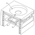
FIG. 7 is a partial perspective view of the present invention;
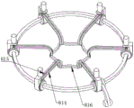
FIG. 8 is a perspective view of a replacement assembly of the present invention;
FIG. 9 is a first partial perspective view of the replacement assembly of the present invention;
FIG. 10 is a second partial perspective view of the replacement assembly of the present invention;
fig. 11 is a schematic partial perspective view of a filter assembly according to the present invention.
Reference numerals: 1. an operation table; 11. a filter tank; 12. a sandwich panel; 2. a dewatering device; 3. a drive assembly; 31. a drive motor; 32. a first bevel gear; 33. a second bevel gear; 34. a drive rod; 35. a gear shaft; 351. a contact block; 352. fixing the ball; 4. an adjustment assembly; 41. driving an electric cylinder; 42. an adjusting bracket; 43. positioning blocks; 44. a rotating shaft; 5. a dewatering assembly; 51. sleeving a frame; 52. a top cover; 53. a fixed block; 54. a support frame; 55. a hinged block; 56. a connecting frame; 57. a compression roller; 6. a scraping component; 61. moving the plate; 62. pushing the electric cylinder; 63. a connecting seat; 64. a scraping plate; 65. a material receiving box; 66. a working electric cylinder; 7. a filtration device; 8. replacing the component; 81. replacing the parts; 811. a hydraulic telescopic rod; 812. a clamping frame; 813. a rotating shaft; 814. a first hinge frame; 815. a second hinge frame; 816. connecting blocks; 82. a support jacket frame; 83. rotating the grip; 84. an elastic filter cloth; 9. a filter assembly; 91. a filter plate; 92. a connecting pipe; 93. and a collection box.
Detailed Description
In order to make the objects, technical solutions and advantages of the present invention more apparent, the technical solutions of the present invention will be clearly and completely described below with reference to the specific embodiments of the present invention and the accompanying drawings. It is to be understood that the described embodiments are merely exemplary of the invention, and not restrictive of the full scope of the invention. All other embodiments, which can be derived by a person skilled in the art from the embodiments given herein without making any creative effort, shall fall within the protection scope of the present invention.
The technical solutions provided by the embodiments of the present invention are described in detail below with reference to the accompanying drawings.
Referring to fig. 1 to 11, an embodiment of the present invention provides a starch dehydration apparatus, including an operation table 1, where the operation table 1 is placed on the ground, a sandwich plate 12 is disposed on the operation table 1, and further including a dehydration device 2, where the dehydration device 2 is mounted at the top of the operation table 1 and is in rotating fit with the operation table 1, the dehydration device 2 includes a driving component 3, an adjusting component 4, a dehydration component 5, and a scraping component 6, the driving component 3 is mounted on a side wall of the operation table 1 and is in rotating fit with the operation table 1, the adjusting component 4 is mounted at the top of the sandwich plate 12 and is in rotating fit with the driving component 3, the dehydration component 5 is mounted on the driving component 3 and is in rotating fit with the driving component 3, and the scraping component 6 is mounted on the dehydration component 5 and is in sliding fit with the dehydration component 5; according to the invention, most of moisture in the starch can be effectively extruded and discharged through the dehydration device 2, so that the dehydration efficiency of the starch is improved, the moisture residual quantity in the starch is lower, the dehydrated starch can be scraped and collected, the collection efficiency of the starch is improved, and the starch is prevented from being adhered to the elastic filter cloth 84 to cause difficulty in collection of the starch.
Preferably, the driving assembly 3 comprises a driving motor 31, a first bevel gear 32, a second bevel gear 33 and a driving rod 34, the driving motor 31 is fixedly arranged on the inner wall of the operating platform 1, the first bevel gear 32 is arranged on the main shaft of the driving motor 31 and is in transmission fit with the main shaft of the driving motor 31, the driving rod 34 is installed on the operating table 1 and is in running fit with the operating table 1, a gear shaft 35 is arranged on the driving rod 34, the first bevel gear 32 is engaged with the second bevel gear 33, the bottom of the driving rod 34 is provided with a baffle, the second bevel gear 33 is positioned at the bottom of the operating platform 1 and is in rotating fit with the operating platform 1, the second bevel gear 33 is positioned at the lower part of the gear shaft 35, the side wall of the second bevel gear 33 contacting with the gear shaft 35 is provided with a tooth groove meshed with the second bevel gear, the tooth grooves are in sliding fit with the gear shaft 35, and the driving rod 34 can slide up and down in the axial direction of the second bevel gear 33; when an operator pours the non-dehydrated starch onto the elastic filter cloth 84 of the filtering device 7, the driving motor 31 drives the first bevel gear 32 to rotate to drive the second bevel gear 33 to rotate, the second bevel gear 33 rotates to drive the gear shaft 35 to rotate the driving rod 34, the gear shaft 35 on the driving rod 34 drives the sleeving frame 51 on the dehydrating assembly 5 to rotate, and the non-dehydrated starch on the elastic filter cloth 84 is dehydrated through the two pressing rollers 57 on the sleeving frame 51.
Preferably, the adjusting assembly 4 includes an electric driving cylinder 41, an adjusting bracket 42, a positioning block 43 and a rotating shaft 44, the electric driving cylinder 41 is installed on the top of the sandwich plate 12, one end of the adjusting bracket 42 is installed on a stroke slider of the electric driving cylinder 41, a slider is arranged on the adjusting bracket 42, the positioning block 43 is fixedly installed on the top of the sandwich plate 12, the slider on the adjusting bracket 42 is in sliding fit with the positioning block 43, the rotating shaft 44 is sleeved on the driving rod 34 and is in rotating fit with the driving rod 34, two contact blocks 351 are fixedly arranged on the driving rod 34, the rotating shaft 44 is located between the two contact blocks 351, and one end of the adjusting bracket 42 is fixedly connected with the rotating shaft 44; after the dehydration assembly 5 completes dehydration on the starch on the filtering device 7, the driving electric cylinder 41 drives the adjusting frame 42 to move on the positioning block 43, the adjusting frame 42 drives the rotating shaft 44 to abut against the two abutting blocks 351 so as to drive the driving rod 34 to move, the driving rod 34 drives the top cover 52 on the dehydration assembly 5 to move, and the top cover 52 moves to enable the connecting frame 56 to move downwards to scrape the starch adhered to the elastic filter cloth 84 after dehydration through the matching scraping assembly 6 to complete the operation.
Preferably, the dewatering component 5 comprises a sleeve frame 51, a top cover 52, a support frame 54, a hinged block 55, a connecting frame 56 and two press rollers 57, the sleeve frame 51 is installed on the operating platform 1 and is in running fit with the operating platform 1, the sleeve frame 51 is meshed with the gear shaft 35 and is in sliding fit with the gear shaft 35, a fixed ball 352 is fixedly arranged at the top of the driving rod 34, the top cover 52 is installed on the fixed ball 352 and is in running fit with the fixed ball 352, fixed blocks 53 are symmetrically arranged on two sides of the top cover 52, the support frame 54 is fixedly installed on the sleeve frame 51, a clamping groove is arranged on the support frame 54, one of the fixed blocks 53 is in sliding fit with the clamping groove on the support frame 54, one end of the hinged block 55 is in hinged fit with the other fixed block 53, the connecting frame 56 is hinged at the other end of the hinged block 55, the connecting frame 56 is in sliding fit with the sleeve frame 51, the two compression rollers 57 are respectively and rotatably arranged on the supporting frame 54 and the sleeving frame 51; when the driving motor 31 drives the driving rod 34 to rotate, the gear shaft 35 on the driving rod 34 drives the sleeving frame 51 to rotate, the sleeving frame 51 rotates to enable the two pressing rollers 57 to press and squeeze the starch which is not dehydrated on the filtering device 7, the starch is pressed back and forth through the two pressing rollers 57, most of moisture in the starch can be effectively squeezed and discharged, the starch dehydration efficiency is improved, the moisture residual quantity in the starch is lower, after the starch is dehydrated, the driving electric cylinder 41 drives the driving rod 34 to move, the fixing ball 352 on the driving rod 34 pushes against the top cover 52 to enable the top cover 52 to deflect, the top cover 52 deflects to enable one fixing block 53 to slide in the chute on the supporting frame 54, the other fixing block 53 drives the hinge block 55 to move, the hinge block 55 drives the connecting frame 56 to move downwards on the sleeving frame 51, the scraping component 6 is enabled to cling to the elastic filtering cloth 84, and the sleeving frame 51 rotates, starch after the cooperation is scraped the material subassembly 6 and is gone up the dehydration to elastic filter cloth 84 and scrape, has improved the collection efficiency to starch, has prevented that starch from gluing the condition of being difficult to collect on elastic filter cloth 84.
Preferably, the scraping assembly 6 includes a moving plate 61, a pushing electric cylinder 62, a connecting seat 63, a scraping plate 64, a material receiving box 65 and two working electric cylinders 66, the moving plate 61 is mounted on the connecting seat 56 and is in sliding fit with the connecting seat 56, the pushing electric cylinder 62 is fixedly mounted on the side wall of the connecting seat 56, a stroke slider of the pushing electric cylinder 62 is connected with the moving plate 61, the connecting seat 63 is fixedly mounted at the bottom of the moving plate 61, the two working electric cylinders 66 are symmetrically hinged on the connecting seat 63, the scraping plate 64 is hinged with the stroke sliders of the two working electric cylinders 66, and the material receiving box 65 is mounted at the top of the operating platform 1; when scraping subassembly 6 scrapes starch to scraping flitch 64 under the cooperation of dehydration subassembly 5 on, promote electric cylinder 62 and drive movable plate 61 and remove to receiving the material case 65 top, work electric cylinder 66 drives and scrapes flitch 64 and move down on connecting seat 63 this moment, will scrape starch on the flitch 64 and pour into the receipts material operation of accomplishing starch in receiving the material case 65, improved the work efficiency that starch was collected.
Preferably, the operating platform 1 is further provided with a filtering device 7, the top of the operating platform 1 is provided with a filtering tank 11, the filtering device 7 is installed in the filtering tank 11 on the operating platform 1 and is located below the dewatering device 2, the filtering device 7 comprises a replacing component 8 and a filtering component 9, the replacing component 8 is installed at the top of the filtering tank 11, and the filtering component 9 is installed on the replacing component 8; the operator places the non-dehydrated starch on the filtering device 7, the starch and water are separated by the filtering device 7, and the filtered water is discharged through the filtering tank 11.
Preferably, the replacing assembly 8 comprises a support sleeve frame 82, a rotating handle 83, an elastic filter cloth 84 and a replacing member 81, the replacing member 81 is provided with six groups, the six groups of replacing members 81 are identical in structure and are circumferentially arranged on the filter tank 11, the six groups of replacing members 81 respectively comprise a hydraulic telescopic rod 811, a clamping frame 812, a rotating shaft 813, a first hinge frame 814 and a second hinge frame 815, the hydraulic telescopic rod 811 is arranged at the bottom of the filter tank 11, the clamping frame 812 is arranged at the top of the hydraulic telescopic rod 811, the rotating shaft 813 is arranged on the clamping frame 812 and is in rotating fit with the clamping frame 812, the first hinge frame 814 and the second hinge frame 815 are symmetrically hinged on the rotating shafts 813, the first hinge frame 814 on one rotating shaft 813 is fixedly connected with the second hinge frame 815 on the adjacent rotating shaft 813 through a connecting block 816, the support sleeve frame 82 is arranged on the rotating shaft 813 and is in rotating fit with the rotating shaft 813, the rotary handle 83 is fixedly connected with a rotary shaft 813 on one of the replacing parts 81, and the elastic filter cloth 84 is detachably connected with the supporting sleeve frame 82 and the connecting block 816; after the starch is dehydrated, the hydraulic telescopic rod 811 on the replacing part 81 drives the clamping frame 812 to move downwards, so that the two press rollers 57 cannot block the detachment of the elastic filter cloth 84, an operator drives the rotating handle 83 to drive one of the rotating shafts 813 to rotate, the rotating shaft 813 rotates to drive the first hinge frame 814 and the second hinge frame 815 to move and unfold, the first hinge frame 814 and the second hinge frame 815 unfold and drive the adjacent first hinge frame 814 and the second hinge frame 815 to move and unfold through the connecting block 816 so that the adjacent rotating shaft 813 rotates to rotate the six groups of replacing parts 81, the elastic filter cloth 84 connected to the connecting block 816 and the support sleeve frame 82 is turned outwards, the operator can replace and clean the elastic filter cloth 84 after the starch dehydration is completed to improve the working efficiency of the starch dehydration, and the elastic filter cloth 84 is connected to the support sleeve frame 82 and the connecting block 816, after the operator installs the elastic filter cloth 84, the operator drives the rotary handle 83 to tighten the elastic filter cloth 84 on the support bracket 82 and the connecting block 816, so that the elastic filter cloth 84 is not wrinkled to affect the starch dewatering operation.
Preferably, the filter assembly 9 comprises a filter plate 91, a connecting pipe 92 and a collecting box 93, the filter plate 91 is fixedly mounted on the side wall of the clamping frame 812 on the six replacing members 81, the filter plate 91 is provided with a plurality of filter holes, the filter tank 11 is provided with a drain hole, the collecting box 93 is mounted on the top of the sandwich plate 12, and two ends of the connecting pipe 92 are respectively connected with the drain hole and the collecting box 93; the filter plate 91 can make the two press rollers 57 play a supporting role when dewatering the starch on the elastic filter cloth 84, and the dewatered moisture flows into the filter tank 11 through the filter holes on the filter plate 91, then flows into the connecting pipe 92 through the drain holes on the filter tank 11, and then is poured into the collecting box 93 to complete the collection and treatment of the wastewater.
The above description is only for the purpose of illustrating the preferred embodiments of the present invention and is not to be construed as limiting the invention, and any modifications, equivalents, improvements and the like that fall within the spirit and principle of the present invention are intended to be included therein.
Claims (3)
1. A starch dehydration device comprises an operation platform (1), wherein the operation platform (1) is placed on the ground, a sandwich plate (12) is arranged on the operation platform (1), characterized in that the device also comprises a dewatering device (2), the dewatering device (2) is arranged at the top of the operating platform (1) and is rotationally matched with the operating platform (1), the dehydration device (2) comprises a driving component (3), a regulating component (4), a dehydration component (5) and a scraping component (6), the driving component (3) is arranged on the side wall of the operating platform (1) and is in running fit with the operating platform (1), the adjusting component (4) is arranged on the top of the sandwich plate (12) and is in running fit with the driving component (3), the dehydration component (5) is arranged on the driving component (3) and is in running fit with the driving component (3), the scraping component (6) is arranged on the dehydration component (5) and is in sliding fit with the dehydration component (5);
the driving assembly (3) comprises a driving motor (31), a first bevel gear (32), a second bevel gear (33) and a driving rod (34), the driving motor (31) is fixedly installed on the inner wall of the operating platform (1), the first bevel gear (32) is installed on a main shaft of the driving motor (31) and is in transmission fit with the main shaft of the driving motor (31), the driving rod (34) is installed on the operating platform (1) and is in rotation fit with the operating platform (1), a gear shaft (35) is arranged on the driving rod (34), the first bevel gear (32) is meshed with the second bevel gear (33), a baffle is arranged at the bottom of the driving rod (34), the second bevel gear (33) is located at the bottom of the operating platform (1) and is in rotation fit with the operating platform (1), the second bevel gear (33) is located at the lower part of the gear shaft (35), and tooth grooves meshed with the second bevel gear (33) are arranged on the side wall, which is in contact with the gear shaft (35), the tooth grooves are in sliding fit with a gear shaft (35), and the driving rod (34) can slide up and down in the axial direction of the second bevel gear (33);
the adjusting assembly (4) comprises a driving electric cylinder (41), an adjusting frame (42), a positioning block (43) and a rotating shaft (44), the driving electric cylinder (41) is installed at the top of the sandwich plate (12), one end of the adjusting frame (42) is installed on a stroke sliding block of the driving electric cylinder (41), a sliding block is arranged on the adjusting frame (42), the positioning block (43) is fixedly installed at the top of the sandwich plate (12), the sliding block on the adjusting frame (42) is in sliding fit with the positioning block (43), the rotating shaft (44) is sleeved on the driving rod (34) and is in rotating fit with the driving rod (34), two contact blocks (351) are fixedly arranged on the driving rod (34), the rotating shaft (44) is located between the two contact blocks (351), and one end of the adjusting frame (42) is fixedly connected with the rotating shaft (44);
the dehydration component (5) comprises a sleeve-arranging frame (51), a top cover (52), a supporting frame (54), a hinged block (55), a connecting frame (56) and two compression rollers (57), the sleeve-arranging frame (51) is installed on the operating table (1) and is in running fit with the operating table (1), the sleeve-arranging frame (51) is meshed with a gear shaft (35) and is in running fit with the gear shaft (35), a fixing ball (352) is fixedly arranged at the top of the driving rod (34), the top cover (52) is installed on the fixing ball (352) and is in running fit with the fixing ball (352), fixing blocks (53) are symmetrically arranged on two sides of the top cover (52), the supporting frame (54) is fixedly installed on the sleeve-arranging frame (51), a clamping groove is formed in the supporting frame (54), one of the fixing blocks (53) is in running fit with the clamping groove in the supporting frame (54), one end of the hinged block (55) is in hinged fit with the other fixing block (53), the connecting frame (56) is hinged to the other end of the hinge block (55), the connecting frame (56) is in sliding fit with the sleeving frame (51), and the two pressing rollers (57) are respectively and rotatably arranged on the supporting frame (54) and the sleeving frame (51);
the scraping component (6) comprises a moving plate (61), a pushing electric cylinder (62), a connecting seat (63), a scraping plate (64), a material receiving box (65) and two working electric cylinders (66), the moving plate (61) is arranged on the connecting frame (56) and is in sliding fit with the connecting frame (56), the pushing electric cylinder (62) is fixedly arranged on the side wall of the connecting frame (56), the stroke slide block of the pushing electric cylinder (62) is connected with the moving plate (61), the connecting seat (63) is fixedly arranged at the bottom of the moving plate (61), the two working electric cylinders (66) are symmetrically hinged on the connecting seat (63), the scraping plate (64) is hinged to the connecting seat (63), the scraping plate (64) is hinged to the stroke sliding blocks of the two working electric cylinders (66), and the material collecting box (65) is installed at the top of the operating platform (1);
still be equipped with filter equipment (7) on operation panel (1), the top of operation panel (1) is equipped with filter tank (11), filter equipment (7) are installed in filter tank (11) on operation panel (1) and are located the below of dewatering device (2), filter equipment (7) are including changing subassembly (8) and filtering component (9), change the top at filter tank (11) in subassembly (8), filtering component (9) are installed on changing subassembly (8).
2. Starch dewatering apparatus according to claim 1, characterized in that the change assembly (8) comprises a support jacket frame (82), a rotary handle (83), an elastic filter cloth (84) and a change member (81), the change member (81) is provided with six groups, six groups of the change member (81) are arranged on the filter tank (11) in the same structure and in the same circumference, the six groups of the change member (81) each comprise a hydraulic telescopic rod (811), a snap frame (812), a rotating shaft (813), a first hinged frame (814) and a second hinged frame (815), the hydraulic telescopic rod (811) is arranged at the bottom of the filter tank (11), the snap frame (812) is arranged at the top of the hydraulic telescopic rod (811), the rotating shaft (813) is arranged on the snap frame (812) and is in rotational fit with the snap frame (812), the first hinged frame (814) and the second hinged frame (815) are symmetrically hinged on the rotating shaft (813), the first hinge frame (814) on one rotating shaft (813) is fixedly connected with the second hinge frame (815) on the adjacent rotating shaft (813) through a connecting block (816), the supporting sleeve frame (82) is installed on the rotating shaft (813) and is in running fit with the rotating shaft (813), the rotating handle (83) is fixedly connected with the rotating shaft (813) on one replacing piece (81), and the elastic filter cloth (84) is detachably connected to the supporting sleeve frame (82) and the connecting block (816).
3. The starch dewatering apparatus according to claim 2, wherein the filter assembly (9) comprises a filter plate (91), a connecting pipe (92) and a collecting box (93), the filter plate (91) is fixedly mounted on the side wall of the clamping frame (812) on the six sets of replacing members (81), the filter plate (91) is provided with a plurality of filter holes, the filter tank (11) is provided with drain holes, the collecting box (93) is mounted on the top of the sandwich plate (12), and two ends of the connecting pipe (92) are respectively connected with the drain holes and the collecting box (93).
Priority Applications (1)
| Application Number | Priority Date | Filing Date | Title |
|---|---|---|---|
| CN202110840839.6A CN113354746B (en) | 2021-07-26 | 2021-07-26 | Starch dehydration equipment |
Applications Claiming Priority (1)
| Application Number | Priority Date | Filing Date | Title |
|---|---|---|---|
| CN202110840839.6A CN113354746B (en) | 2021-07-26 | 2021-07-26 | Starch dehydration equipment |
Publications (2)
| Publication Number | Publication Date |
|---|---|
| CN113354746A CN113354746A (en) | 2021-09-07 |
| CN113354746B true CN113354746B (en) | 2022-03-25 |
Family
ID=77540286
Family Applications (1)
| Application Number | Title | Priority Date | Filing Date |
|---|---|---|---|
| CN202110840839.6A Active CN113354746B (en) | 2021-07-26 | 2021-07-26 | Starch dehydration equipment |
Country Status (1)
| Country | Link |
|---|---|
| CN (1) | CN113354746B (en) |
Families Citing this family (1)
| Publication number | Priority date | Publication date | Assignee | Title |
|---|---|---|---|---|
| CN115433288A (en) * | 2022-08-31 | 2022-12-06 | 陈越洲 | Centrifugal compression type starch dewatering structure |
Family Cites Families (4)
| Publication number | Priority date | Publication date | Assignee | Title |
|---|---|---|---|---|
| ATE94156T1 (en) * | 1989-11-03 | 1993-09-15 | Hoppe & Partner | MUD DRAINING DEVICE. |
| CN109529440B (en) * | 2019-01-24 | 2021-05-14 | 王�华 | Gasification fly ash dehydration treatment process |
| CN211611875U (en) * | 2019-12-30 | 2020-10-02 | 内蒙古薯元康生物科技有限公司 | Vacuum dehydrator for producing starch |
| CN112923692A (en) * | 2021-02-01 | 2021-06-08 | 抚州市鹤达实业有限公司 | Rotary dehydration device for modified starch |
-
2021
- 2021-07-26 CN CN202110840839.6A patent/CN113354746B/en active Active
Also Published As
| Publication number | Publication date |
|---|---|
| CN113354746A (en) | 2021-09-07 |
Similar Documents
| Publication | Publication Date | Title |
|---|---|---|
| CN113354746B (en) | Starch dehydration equipment | |
| CN214861554U (en) | Dry-wet sludge mixing, homogenizing and dehydrating device | |
| CN112057923A (en) | Primary sewage impurity recovery environmental protection processing apparatus | |
| CN114133054B (en) | Stable textile dye recovery device | |
| CN212418977U (en) | Inside cleaning device of reation kettle for chemical industry | |
| CN212246727U (en) | Automatic system of sludge filter press | |
| CN218083641U (en) | Thermoplastic elastomer hydroextractor | |
| CN115487554B (en) | Van-type filter press convenient for collecting sludge | |
| CN219195493U (en) | Paper pulp filtering device of paper machine for paper products | |
| CN215742209U (en) | Camellia oil pressure filter that dewaxes | |
| CN216760913U (en) | Lees separator is used in production of strong aromatic white spirit | |
| CN113248102B (en) | Sludge press filtration device for sewage treatment | |
| CN212143088U (en) | Centrifuge equipment with function of making an uproar is fallen | |
| CN211620334U (en) | Sludge plate-and-frame filter press conveying device | |
| CN210620568U (en) | Belt filter press for sludge dewatering | |
| CN203436909U (en) | Spring-drawing material-scraping device of filter strip | |
| CN208403150U (en) | A kind of vegetable dehumidifier | |
| CN209204844U (en) | Rotary drum filter | |
| CN219815493U (en) | Fermentation filtration treatment equipment | |
| CN220047208U (en) | Dyeing wastewater recycling treatment device | |
| CN219861012U (en) | Filter pressing device for sludge treatment | |
| CN217699617U (en) | Plant raw material extract centrifugal separation device | |
| CN215551129U (en) | Bright bamboo shoot squeezer | |
| CN115043568B (en) | Sludge dewatering equipment for industrial sewage treatment | |
| CN218577065U (en) | Construction waste dehydration device |
Legal Events
| Date | Code | Title | Description |
|---|---|---|---|
| PB01 | Publication | ||
| PB01 | Publication | ||
| SE01 | Entry into force of request for substantive examination | ||
| SE01 | Entry into force of request for substantive examination | ||
| GR01 | Patent grant | ||
| GR01 | Patent grant | ||
| TR01 | Transfer of patent right | ||
| TR01 | Transfer of patent right |
Effective date of registration: 20221109 Address after: Room 619, No.10, No.300, Changjiang Road, Yantai Economic and Technological Development Zone, Shandong Province 264006 Patentee after: Yantai Yunhui Intelligent Technology Co.,Ltd. Address before: 265400 no.668, Jincheng Road, Zhaoyuan City, Yantai City, Shandong Province Patentee before: YANTAI ORIENTAL PROTEIN TECH Co.,Ltd. |