CN113333552B - Intelligent stamping equipment and stamping method for automobile parts - Google Patents
Intelligent stamping equipment and stamping method for automobile parts Download PDFInfo
- Publication number
- CN113333552B CN113333552B CN202110792040.4A CN202110792040A CN113333552B CN 113333552 B CN113333552 B CN 113333552B CN 202110792040 A CN202110792040 A CN 202110792040A CN 113333552 B CN113333552 B CN 113333552B
- Authority
- CN
- China
- Prior art keywords
- stamping
- punching press
- control module
- piece
- driving motor
- Prior art date
- Legal status (The legal status is an assumption and is not a legal conclusion. Google has not performed a legal analysis and makes no representation as to the accuracy of the status listed.)
- Active
Links
Images


Classifications
-
- B—PERFORMING OPERATIONS; TRANSPORTING
- B21—MECHANICAL METAL-WORKING WITHOUT ESSENTIALLY REMOVING MATERIAL; PUNCHING METAL
- B21D—WORKING OR PROCESSING OF SHEET METAL OR METAL TUBES, RODS OR PROFILES WITHOUT ESSENTIALLY REMOVING MATERIAL; PUNCHING METAL
- B21D22/00—Shaping without cutting, by stamping, spinning, or deep-drawing
- B21D22/02—Stamping using rigid devices or tools
-
- B—PERFORMING OPERATIONS; TRANSPORTING
- B21—MECHANICAL METAL-WORKING WITHOUT ESSENTIALLY REMOVING MATERIAL; PUNCHING METAL
- B21D—WORKING OR PROCESSING OF SHEET METAL OR METAL TUBES, RODS OR PROFILES WITHOUT ESSENTIALLY REMOVING MATERIAL; PUNCHING METAL
- B21D43/00—Feeding, positioning or storing devices combined with, or arranged in, or specially adapted for use in connection with, apparatus for working or processing sheet metal, metal tubes or metal profiles; Associations therewith of cutting devices
- B21D43/003—Positioning devices
-
- B—PERFORMING OPERATIONS; TRANSPORTING
- B21—MECHANICAL METAL-WORKING WITHOUT ESSENTIALLY REMOVING MATERIAL; PUNCHING METAL
- B21D—WORKING OR PROCESSING OF SHEET METAL OR METAL TUBES, RODS OR PROFILES WITHOUT ESSENTIALLY REMOVING MATERIAL; PUNCHING METAL
- B21D55/00—Safety devices protecting the machine or the operator, specially adapted for apparatus or machines dealt with in this subclass
-
- F—MECHANICAL ENGINEERING; LIGHTING; HEATING; WEAPONS; BLASTING
- F16—ENGINEERING ELEMENTS AND UNITS; GENERAL MEASURES FOR PRODUCING AND MAINTAINING EFFECTIVE FUNCTIONING OF MACHINES OR INSTALLATIONS; THERMAL INSULATION IN GENERAL
- F16F—SPRINGS; SHOCK-ABSORBERS; MEANS FOR DAMPING VIBRATION
- F16F15/00—Suppression of vibrations in systems; Means or arrangements for avoiding or reducing out-of-balance forces, e.g. due to motion
- F16F15/02—Suppression of vibrations of non-rotating, e.g. reciprocating systems; Suppression of vibrations of rotating systems by use of members not moving with the rotating systems
- F16F15/04—Suppression of vibrations of non-rotating, e.g. reciprocating systems; Suppression of vibrations of rotating systems by use of members not moving with the rotating systems using elastic means
- F16F15/08—Suppression of vibrations of non-rotating, e.g. reciprocating systems; Suppression of vibrations of rotating systems by use of members not moving with the rotating systems using elastic means with rubber springs ; with springs made of rubber and metal
Landscapes
- Engineering & Computer Science (AREA)
- Mechanical Engineering (AREA)
- General Engineering & Computer Science (AREA)
- Chemical & Material Sciences (AREA)
- Combustion & Propulsion (AREA)
- Physics & Mathematics (AREA)
- Acoustics & Sound (AREA)
- Aviation & Aerospace Engineering (AREA)
- Punching Or Piercing (AREA)
Abstract
The invention relates to the technical field of intelligent stamping equipment and discloses intelligent stamping equipment and a stamping method for automobile parts. According to the intelligent stamping equipment and stamping method for the automobile parts, the execution part, the second stamping assembly and the first stamping assembly are arranged, the stamping of the automobile parts is operated in a stepping mode, the stamping process is further delicate, the stamping effect is guaranteed, the problem that the height dimension of a formed sheet metal part structure is not uniform due to asymmetric placement between a sheet metal plate and a punch is avoided, and the stability during stamping processing of the equipment is improved by the aid of the cooperation of the execution part and the stamping head.
Description
Technical Field
The invention relates to the technical field of intelligent stamping equipment, in particular to intelligent stamping equipment and a stamping method for automobile parts.
Background
The sheet metal is a comprehensive cold working process aiming at sheet metal (generally below 6 mm), comprising shearing, punching/cutting/compounding, folding, welding, riveting, splicing, forming (such as automobile bodies) and the like, and is characterized in that the thickness of the same part is consistent, products processed by the sheet metal process are called sheet metal parts, the sheet metal parts indicated by different industries are generally different and are mainly used for calling during assembly, the sheet metal stamping mainly comprises basic procedures of blanking, bench workers, hole drawing, punching machine (stamping bending, blanking, corner cutting, blanking and the like), bending and the like, the sheet metal materials suitable for stamping are very many, and the sheet metal materials are widely applied to the electronic and electrical industry, but the following problems can occur in the stamping forming process of the sheet metal parts: the sheet metal parts which can be formed by the stamping device are single in size and style, the integral utilization degree of the same device is low, the satisfaction degree of different sheet metal part forming requirements is low, meanwhile, the stamping device adopts an integral structure, and the integral structure is not convenient to adjust according to the processing requirements; in addition, the pressure cannot be effectively controlled during stamping, so that the precision of the formed part is reduced, and moreover, the workpiece and the die are in rigid contact in the stamping process, so that the workpiece is easily damaged; the sheet metal plate is easy to deviate and warp at two ends when being stamped, the conventional stamping equipment adopts one-step stamping forming, a workpiece is easy to rebound and deform after being stamped, the phenomenon is easy to cause deviation of the integral structure of the stamped sheet metal part, and the asymmetrical placement between the sheet metal plate and a punch is easy to cause non-uniform height and size of the structure of the stamped sheet metal part, so that the intelligent stamping equipment for the automobile parts and the using method thereof are provided to solve the problems.
Disclosure of Invention
The invention aims to solve the technical problem of providing intelligent stamping equipment for automobile parts and a using method thereof aiming at the defects in the prior art.
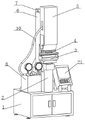
In order to solve the technical problems, the invention adopts the technical scheme that: including the punching press base, be located the surperficial center of punching press base is close to the place ahead and installs the punching press support, is located the punching press headstock is installed on the surface of punching press base and the left end that is close to the punching press support, is located the surface of punching press base and the right-hand member the place ahead that is close to the punching press support install the punching press control box, are located the surface of punching press base and the back mounted who keeps away from the punching press support have the pillar, the front welding of pillar has drive mechanism, drive mechanism's front is provided with the punching press head, the punching press head can go up and down in drive mechanism's front.
The top of punching press support is provided with punching press mechanism, punching press mechanism carries out twice punching press to auto parts material including second punching press subassembly and first punching press subassembly, and the deviation appears when reducing the punching press, is located punching press mechanism's below and be close to the top of punching press support and install stamping forming mechanism, stamping forming mechanism is convenient for restrict punching press part including the shaping groove with support piece to reach the mesh of suitability production.
Preferably, the last surface mounting of punching press headstock has the manometer, the manometer is including first manometer and second manometer, be provided with the regulation and control valve between first manometer and the second manometer, the bottom of regulation and control valve and the last surface welding of punching press headstock utilize punching press headstock and manometer to carry out directly perceived control to stamping equipment, have ensured the effect that stamping device's convenient observation was used, utilize first manometer and second manometer to carry out the distributing type to the process of punching press simultaneously and handle, reach the effect that improve equipment security and reduce equipment and control the degree of difficulty.
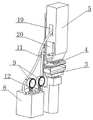
Preferably, the welding of the left side bottom of first manometer has punching press kinetic energy spare one, the one end of punching press kinetic energy spare one extends to the inside and the fixedly connected with executive component of punching press head, the welding of the right side bottom of second manometer has punching press kinetic energy spare two, the one end of punching press kinetic energy spare two and the surperficial bottom welded fastening of executive component, the output shaft and the second punching press subassembly of executive component are connected, the below of second punching press subassembly is passed through the connecting seat and is connected with first punching press subassembly, through setting up the second punching press subassembly, first punching press subassembly and executive component, further refine the flow of punching press, the stable effect of guarantee punching press, utilize the cooperation of executive component and punching press head simultaneously, improve equipment punching press man-hour security, guide mouthful one has been seted up in the left side of punching press head, the surface of punching press kinetic energy spare one and the inner wall fixed connection of guide mouthful one, guide mouthful two has been seted up to the inside of punching press kinetic energy spare two, the one end of punching press kinetic energy spare extends to the inside of punching press head and with the inner wall fixed connection of guide mouthful two, utilize guide mouthful one and guide mouthful two, make the effect of punching press kinetic energy spare and punching press piece two between the two more directly perceived.
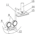
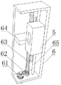
Preferably, drive mechanism is including driving motor, driving belt, threaded rod, lifter plate and location guide arm, driving belt cup joints in driving motor's output shaft surface, the surface of threaded rod is connected through driving belt and driving motor's output shaft surface transmission, the lifter plate screw thread cup joints on the threaded rod on the surface, the one end welded fastening of lifter plate has the punching press head, the both ends of location guide arm and drive mechanism's internal surface welded fastening, just the surface of location guide arm cup joints with lifter plate inner wall activity, utilizes driving motor and driving belt to drive the threaded rod and rotates for stability and punching press intensity when punching press operation are carried out to the punching press head under the cooperation of lifter plate are protected, thereby reach the purpose of stabilizing the safety in production and processing.
Preferably, the bottom surface in shaping groove and the top welded fastening who supports the piece, the below that supports the piece is provided with the change subassembly with the top welded fastening of punching press support, the top of changing the subassembly and the lower surface swing joint who supports the piece, the one end of changing the subassembly is provided with the screw thread post, support the bottom of piece and seted up the mounting groove, the screw thread with the surface looks adaptation of screw thread post is seted up to the inner wall of mounting groove, the top of changing the subassembly and the bottom surface threaded connection who supports the piece, through the change subassembly with support the piece be connected, reach the shaping groove and support quick replacement's effect to it is more convenient to ensure its process of changing.
Preferably, resistance to compression mechanism is including resistance to compression support piece and location platform, the upper surface of location platform and resistance to compression support piece's lower surface welded fastening, and the shape of location platform is for falling trapezoidally, the trapezoidal bottom surface welded fastening of location platform has the location inserted bar, the constant head tank with location platform looks adaptation is seted up to the inner chamber bottom surface in shaping groove, and the surface of location platform and the inner wall joint in shaping groove, through mutually supporting of location platform and location inserted bar, reaches the effect that resistance to compression mechanism is more convenient when installing on the shaping groove, and the production machining efficiency of improve equipment on another angle simultaneously.
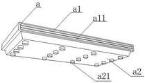
Preferably, resistance to compression support piece's inner chamber welded fastening has soft limiting plate, the upper surface of soft limiting plate evenly is provided with spacing post, the lower surface of soft limiting plate is provided with the resistance to compression rubber ball, the dashpot with resistance to compression rubber ball looks adaptation is seted up to the inside of spacing post, and spacing post and resistance to compression rubber ball one-to-one, utilizes soft limiting plate to accept stamping pressure, coordinates soft limiting plate and resistance to compression support piece's material characteristic, protects the work piece, utilizes the mutual matching between resistance to compression rubber ball and the spacing post simultaneously, the life-span when further ensureing the equipment use and the security when the punching press.
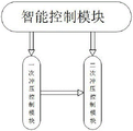
Preferably, the inside of punching press control box is provided with intelligent control module, driving motor intelligent control module and secondary punching press control module, the wiring end electric wire connection of once punching press control module has driving motor intelligent control module, driving motor intelligent control module's wiring end electric connection has the driving motor execution subassembly that sets up in driving motor inside, secondary punching press control module's wiring end electric wire connection has second manometer intelligent control module and second manometer execution subassembly, utilizes intelligent control module to ensure the intelligent effect when equipment uses, utilizes once punching press control module and secondary punching press control module to control the process of punching press respectively simultaneously, further improves the interference killing feature when punching press equipment punching press.
An intelligent stamping device for automobile parts and a using method thereof comprise the following steps:
the method comprises the following steps: placing automobile part materials to be punched on a forming groove, adjusting the positions of the automobile part materials on the forming groove to enable the automobile part materials to be punched to be placed in order and symmetrically, and then controlling the equipment through an intelligent control module in a punch control box;
step two: the intelligent control module in the stamping control box controls a driving motor in the transmission mechanism to start, and an output shaft of the driving motor is matched with a transmission belt to drive a threaded rod to rotate, so that the lifting plate drives a stamping head to move downwards to drive a first stamping assembly to stamp automobile part materials at one time;
step three: the intelligent control module controls the secondary stamping control module and the pressure gauge intelligent control module, the pressure gauge execution assembly is started, stamping work is carried out through the stamping kinetic energy assembly I, the stamping kinetic energy assembly II and the execution assembly, meanwhile, the execution assembly drives the second stamping assembly to extrude the first stamping assembly, and then secondary stamping is carried out on automobile part materials;
step four: make auto parts material shaping in the shaping groove through twice punching press, utilize the ductility cooperation of shaping groove and auto parts material, carry out auto parts punching press suitability production and processing, take off fashioned auto parts after the production is accomplished, rotate the shaping groove and prop the piece, take off it from changing the subassembly, change the adjustment to it.
By adopting the technical scheme, the invention can bring the following beneficial effects:
1. according to the intelligent stamping equipment and stamping method for the automobile parts, the execution part, the second stamping assembly and the first stamping assembly are arranged, the stamping of the automobile parts is operated in a stepping mode, the stamping process is further delicate, the stamping effect is guaranteed, the problem that the height dimension of a formed sheet metal part structure is not uniform due to asymmetric placement between a sheet metal plate and a punch is avoided, and the stability during stamping processing of the equipment is improved by the aid of the cooperation of the execution part and the stamping head.
2. This automobile part intelligence stamping equipment and stamping method, through setting up the shaping groove and propping piece, limit the marginal ductility region of punching press part, the effect of carrying out adaptation production when reaching the punching press, simultaneously through the connection of changing subassembly and propping piece, reach the effect to shaping groove and propping piece quick replacement, the sheet metal component size and the pattern of having avoided punching device formability is comparatively single, the whole degree of utilization of same device is lower and to the lower problem of the degree of satisfaction of different sheet metal component shaping requirements, utilize the function each other between each structure, make the speed of changing accelerate, time saving and labor saving more, adaptation sets up the effect that different shaping required simultaneously.
3. According to the intelligent stamping equipment and the stamping method for the automobile parts, the first pressure gauge, the second pressure gauge and the stamping power box are arranged, and the structures are matched with one another, so that the stamping equipment is more intuitive to control, the convenient observation and use of the stamping equipment are guaranteed, the safety of the equipment is further improved, and the control difficulty of the equipment is reduced.
4. This auto parts intelligence stamping equipment and stamping method, through setting up second punching press subassembly, first punching press subassembly and executive component, further refine the flow of punching press, accomplish the punching press back to the work piece when first punching press subassembly, certain pressure can continue to be exerted to first punching press subassembly to the second punching press subassembly, prevent that the work piece from taking place to kick-back and warpage, the stable effect of guarantee punching press, utilize the cooperation of executive component and punching press head simultaneously, improve the security that the equipment punching press was processed.
5. This auto parts intelligence stamping equipment and stamping method through setting up location platform, location inserted bar and shaping groove, utilizes the mutual matching between the structure for the efficiency of work piece when punching press production is higher, ensures the dismantlement installation rate of resistance to compression mechanism simultaneously, further improves the convenient degree when equipment uses.
6. This automobile part intelligence stamping equipment and stamping method, through setting up resistance to compression support piece, soft limiting plate, spacing post, dashpot and compression-resistant rubber ball, utilize mutually supporting between each structure in the resistance to compression support piece, when making the punching press work piece, resistance to compression support piece can utilize the material characteristic of self to reduce the rigidity power that work piece and shaping groove direct contact produced, prevent the damage of work piece, utilize the mutual correspondence of dashpot on the spacing post and compression-resistant rubber ball simultaneously, the pressure dispersion that produces the punching press, self safety during the punching press of support equipment, further improve the protection to the work piece.
7. According to the intelligent stamping equipment and the stamping method for the automobile parts, the intelligent control module for the driving motor and the secondary stamping control module are arranged, the mutual matching among the modules is utilized, so that the equipment is more intelligent in use, the use cost of the equipment is further saved, the production time is saved, meanwhile, the primary stamping control module and the secondary stamping control module are utilized to respectively control the stamping process, and the anti-interference capability of the stamping equipment in stamping is further improved.
Drawings
FIG. 1 is a schematic view of an overall structure of an intelligent stamping device for automobile parts, according to the present invention;
FIG. 2 is a schematic view of a stamping head structure of an intelligent stamping apparatus for automobile parts according to the present invention;
FIG. 3 is a schematic structural diagram of an actuator of the intelligent stamping device for automobile parts according to the present invention;
FIG. 4 is a schematic structural view of a stamping forming mechanism of the intelligent stamping device for automobile parts, which is provided by the invention;
FIG. 5 is a schematic structural view of a compression-resistant mechanism of the intelligent stamping device for automobile parts, which is provided by the invention;
FIG. 6 is a schematic view of a soft limiting plate of the intelligent stamping apparatus for automobile parts according to the present invention;
FIG. 7 is a schematic structural view of a transmission mechanism of an intelligent stamping device for automobile parts, according to the present invention;
fig. 8 is a flowchart of an intelligent control module of the intelligent stamping device for automobile parts according to the present invention.
In the figure: 1. stamping the base; 2. punching a support; 3. a punch forming mechanism; 4. a stamping mechanism; 5. punching a head; 6. a transmission mechanism; 61. a drive motor; 62. a drive belt; 63. a threaded rod; 64. a lifting plate; 65. positioning the guide rod; 7. a pillar; 8. stamping a power box; 9. a pressure gauge; 10. stamping a kinetic energy piece I; 11. stamping a kinetic energy part II; 12. a regulating valve; 13. an executive component; 14. a second punch assembly; 15. a first punch assembly; 16. forming a groove; 17. a support member; 18. replacing the component; 19. a first guide port; 20. a second guide port; 21. a stamping control box; a. a compression resistance mechanism; a1, a compression-resistant support member; a11, soft limiting plates; a12, limiting columns; a13, compression-resistant rubber balls; a2, a positioning table; a21, positioning the inserted rod.
Detailed Description
The technical solutions in the embodiments of the present invention will be clearly and completely described below with reference to the drawings in the embodiments of the present invention, and it is obvious that the described embodiments are only a part of the embodiments of the present invention, and not all of the embodiments. All other embodiments, which can be derived by a person skilled in the art from the embodiments given herein without making any creative effort, shall fall within the protection scope of the present invention.
An intelligent stamping device and a stamping method for automobile parts are shown in figures 1-8 and comprise a stamping base 1, a stamping support 2 is arranged on the surface center of the stamping base 1 and close to the front of the stamping support 2, a stamping power box 8 is arranged on the surface of the stamping base 1 and close to the left end of the stamping support 2, a stamping control box 21 is arranged on the surface of the stamping base 1 and close to the front of the right end of the stamping support 2, a support 7 is arranged on the surface of the stamping base 1 and far away from the back of the stamping support 2, a transmission mechanism 6 is welded on the front of the support 7, a stamping head 5 is arranged on the front of the transmission mechanism 6, and the stamping head 5 can lift on the front of the transmission mechanism 6.
Punching press mechanism 4 is provided with in punching press support 2's top, punching press mechanism 4 is including second punching press subassembly 14 and first punching press subassembly 15, be located punching press mechanism 4's below and be close to punching press support 2's top and install punching press mechanism 3, punching press mechanism 3 is including shaping groove 16 and support piece 17, the inner chamber in shaping groove 16 is provided with resistance to compression mechanism a, through setting up shaping groove 16 and support piece 17, limit the marginal ductility region of punching press part, reach the effect of carrying out the suitability production when punching press.
Further, the last surface mounting of punching press headstock 8 has manometer 9, manometer 9 is including first manometer and second manometer, be provided with regulation and control valve 12 between first manometer and the second manometer, the bottom of regulation and control valve 12 and the last surface welding of punching press headstock 8, through setting up first manometer, second manometer and punching press headstock 8, utilize mutually supporting between the structure, make controlling of stamping equipment more directly perceived, the convenient observation of stamping equipment is used has been ensured, the security of equipment has also further been improved simultaneously, the degree of difficulty of controlling of equipment has been reduced.
Furthermore, a first stamping kinetic energy part 10 is welded at the bottom end of the left side of the first pressure gauge, one end of the first stamping kinetic energy part 10 extends to the inside of the stamping head 5, an executive part 13 is fixedly connected with the inside of the stamping head 5, a second stamping kinetic energy part 11 is welded at the bottom end of the right side of the second pressure gauge, one end of the second stamping kinetic energy part 11 is fixedly welded with the bottom end of the surface of the executive part 13, an output shaft of the executive part 13 is connected with a second stamping component 14, the lower portion of the second stamping component 14 is connected with a first stamping component 15 through a connecting seat, through the arrangement of the second stamping component 14, the first stamping component 15 and the executive part 13, the stamping process is further refined, the stable effect of stamping is guaranteed, meanwhile, the cooperation of the executive part 13 and the stamping head 5 is utilized, the safety of the stamping device during stamping is improved, a first guide opening 19 is formed in the left side of the stamping head 5, the outer surface of the first stamping kinetic energy part 10 is fixedly connected with the inner wall of the first guide opening 19, a second guide opening 20 is formed in the inside of the stamping head 5, and the guide opening 19 are utilized, and the stamping kinetic energy part 11 and the stamping part are connected with the stamping part in front.
It is worth noting that the transmission mechanism 6 comprises a driving motor 61, a transmission belt 62, a threaded rod 63, a lifting plate 64 and a positioning guide rod 65, the transmission belt 62 is sleeved on the surface of an output shaft of the driving motor 61, the surface of the threaded rod 63 is in transmission connection with the surface of the output shaft of the driving motor 61 through the transmission belt 62, the lifting plate 64 is in threaded sleeve connection with the surface of the threaded rod 63, a stamping head 5 is welded and fixed to one end of the lifting plate 64, two ends of the positioning guide rod 65 are welded and fixed to the inner surface of the transmission mechanism, the surface of the positioning guide rod 65 is movably sleeved with the inner wall of the lifting plate 64, the driving motor 22 and the transmission belt 23 are used for driving the threaded rod 24 to rotate, stamping strength of the stamping head 5 during stamping operation under the cooperation of the lifting plate 25 is guaranteed, and stability of the lifting plate 25 when driving the stamping head 5 to move can be effectively improved through the positioning guide rod 26.
It is worth to explain, the bottom surface of the forming groove 16 is welded and fixed with the top of the supporting piece 17, the replacing component 18 welded and fixed with the top of the stamping support 2 is arranged below the supporting piece 17, the top of the replacing component 18 is movably connected with the lower surface of the supporting piece 17, the forming groove 16 and the supporting piece 17 are arranged, the edge ductility area of the stamping part is limited, the effect of adaptive production during stamping is achieved, meanwhile, through the connection of the replacing component 18 and the supporting piece 17, the effect of quickly replacing the forming groove 16 and the supporting piece 17 is achieved, the problem that the sheet metal part formed by the stamping device is single in size and pattern is low in overall utilization degree, the problem that the satisfaction degree of different sheet metal part forming requirements is low is solved, the mutual operation between structures is utilized, the replacing speed is accelerated, time and labor are saved, meanwhile, the effect of different forming requirements is set in the adaptive manner, a threaded column is arranged at one end of the replacing component 18, a mounting groove is formed at the bottom of the supporting piece 17, a thread matched with the outer surface of the threaded column is formed on the inner wall of the mounting groove, the mounting groove is connected with the replacing thread of the supporting piece 18, and the supporting piece 17, and the quick disassembling process of the stamping forming groove is more convenient and convenient.
In addition, the compression-resistant mechanism a comprises a compression-resistant support member a1 and a positioning table a2, the upper surface of the positioning table a2 is welded and fixed with the lower surface of the compression-resistant support member a1, the positioning table a2 is in an inverted trapezoid shape, a positioning inserted rod a21 is welded and fixed with the trapezoid bottom surface of the positioning table a2, a positioning groove matched with the positioning table a2 is formed in the bottom surface of the inner cavity of the molding groove 16, the surface of the positioning table a2 is clamped with the inner wall of the molding groove 16, the stability of the compression-resistant mechanism a when the compression-resistant mechanism a is connected with the molding groove 16 is enhanced through the mutual matching of the positioning table a2 and the positioning inserted rod a21, meanwhile, the compression-resistant mechanism a is more convenient to install on the molding groove 16, a soft limiting plate a11 is welded and fixed in the inner cavity of the compression-resistant support member a1, the upper surface of soft limiting plate a11 evenly is provided with spacing post an 12, the lower surface of soft limiting plate a11 is provided with resistance to compression rubber ball a13, the dashpot with resistance to compression rubber ball a13 looks adaptation is seted up to spacing post a 12's inside, and spacing post an 12 and resistance to compression rubber ball a13 one-to-one, utilize soft limiting plate a11 to accept stamping pressure, again by soft limiting plate a11 and resistance to compression support piece a 1's material characteristic, protect the work piece, utilize mutual matching between resistance to compression rubber ball a13 and spacing post an 12 simultaneously, the pressure dispersion that produces when will punching press, the too big loss that causes equipment of pressure when preventing the punching press, in the life-span when the guarantee equipment uses, security when improving the punching press.
As shown in fig. 1 to 8, an intelligent control module of a driving motor and a secondary stamping control module are arranged inside the stamping control box 21, a wiring terminal of the primary stamping control module is electrically connected with the intelligent control module of the driving motor, a wiring terminal of the intelligent control module of the driving motor is electrically connected with a driving motor execution assembly arranged inside the driving motor 61, and a wiring terminal of the secondary stamping control module is electrically connected with an intelligent control module of a second pressure gauge and the execution assembly of the second pressure gauge.
In this embodiment, through setting up intelligent control module, a punching press control module and secondary punching press control module, utilize the intermodule to mutually support for it is more intelligent when equipment uses, further saves the cost of equipment use, practices thrift the time of production, utilizes a punching press control module and secondary punching press control module to control the process of punching press respectively simultaneously, interference killing feature when further improving the punching press of stamping equipment.
An intelligent stamping device for automobile parts and a using method thereof comprise the following steps:
the method comprises the following steps: placing the automobile part material to be punched on the forming groove 16, adjusting the position of the automobile part material on the forming groove 16 to ensure that the material to be punched is placed in order and symmetrically, and then controlling the equipment by an intelligent control module in the punch control box 21;
step two: the intelligent control module in the stamping control box 21 controls the driving motor 61 in the transmission mechanism 6 to be started, and the output shaft of the driving motor 61 is matched with the transmission belt 62 to drive the threaded rod 63 to rotate, so that the lifting plate 64 drives the stamping head 5 to move downwards to drive the first stamping assembly 15 to stamp the automobile part material for one time;
step three: the secondary stamping control module and the pressure gauge intelligent control module are controlled by the intelligent control module, the pressure gauge execution assembly is started, stamping work is carried out through the stamping kinetic energy assembly I10, the stamping kinetic energy assembly II 11 and the execution assembly 13, meanwhile, the execution assembly 13 drives the second stamping assembly 14 to extrude the first stamping assembly 15, and then secondary stamping is carried out on automobile part materials; step four: the automobile part material is molded in the molding groove 16 through twice stamping, the molding groove 16 is matched with the ductility of the automobile part material, the automobile part stamping adaptive production processing is carried out, the molded automobile part is taken down after the production is finished, the molding groove 16 and the support piece 17 are rotated, the molded automobile part is taken down from the replacing component 18, and the replacement and adjustment are carried out on the molded automobile part.
The working principle is that before stamping, firstly, automobile part materials to be stamped are placed on a forming groove 16, the positions of the automobile part materials are adjusted on the forming groove 16, the materials to be stamped are placed in order and symmetrically, then, an intelligent control module and an intelligent control module of a driving motor in a stamping control box 21 are used for controlling a driving motor 61 in a transmission mechanism 6 to be started, an output shaft of the driving motor 61 is matched with a transmission belt 62 to drive a threaded rod 63 to rotate, so that a lifting plate 64 drives a stamping head 5 to move downwards to drive a first stamping assembly 15 to stamp the automobile part materials at one time, then, the intelligent control module is used for controlling a secondary stamping control module and an intelligent control module of a second pressure gauge, and a pressure gauge execution assembly is started, carry out stamping work through punching press kinetic energy piece one 10, punching press kinetic energy piece two 11 and executive component 13, drive second punching press subassembly 14 through executive component 13 simultaneously and extrude first punching press subassembly 15, then carry out the secondary punching press to the auto parts material, at the in-process of punching press, utilize resistance to compression support piece a1 and soft limiting plate a11 to protect the work piece, utilize mutual matching between resistance to compression rubber ball a13 and limiting post a12 simultaneously, the pressure dispersion that produces when will punching press, protect work piece and equipment, after the punching press is accomplished, take off fashioned auto parts, if need to change resistance to compression mechanism a, with locating platform a2 from the shaping groove 16 take off can, if need to change into type groove 16, rotate shaping groove 16 and support piece 17, it can from changing subassembly 18 with it.
The invention provides an intelligent stamping device for automobile parts and a using method thereof, and a plurality of methods and ways for implementing the technical scheme are provided, the above description is only a preferred embodiment of the invention, and it should be noted that, for a person skilled in the art, a plurality of improvements and decorations can be made without departing from the principle of the invention, and the improvements and decorations should also be regarded as the protection scope of the invention. All the components not specified in the present embodiment can be realized by the prior art.
Claims (2)
1. The utility model provides an auto parts intelligence stamping equipment, includes punching press base (1), its characterized in that: the stamping device is characterized in that a stamping support (2) is arranged at the center of the surface of the stamping base (1) close to the front, a stamping power box (8) is arranged at the left end of the surface of the stamping base (1) close to the stamping support (2), a stamping control box (21) is arranged at the right end of the surface of the stamping base (1) close to the stamping support (2), a support column (7) is arranged at the back of the surface of the stamping base (1) far away from the stamping support (2), a transmission mechanism (6) is welded on the front of the support column (7), a stamping head (5) is arranged on the front of the transmission mechanism (6), and the stamping head (5) can lift on the front of the transmission mechanism (6);
a stamping mechanism (4) is arranged above the stamping support (2), the stamping mechanism (4) comprises a second stamping component (14) and a first stamping component (15), a stamping forming mechanism (3) is arranged below the stamping mechanism (4) and close to the top of the stamping support (2), the stamping forming mechanism (3) comprises a forming groove (16) and a supporting piece (17), and an inner cavity of the forming groove (16) is provided with a compression resisting mechanism (a);
a pressure gauge (9) is mounted on the upper surface of the stamping power box (8), the pressure gauge (9) comprises a first pressure gauge and a second pressure gauge, a regulating valve (12) is arranged between the first pressure gauge and the second pressure gauge, and the bottom of the regulating valve (12) is welded with the upper surface of the stamping power box (8);
a first stamping kinetic energy part (10) is welded at the bottom end of the left side of the first pressure gauge, one end of the first stamping kinetic energy part (10) extends into the stamping head (5) and is fixedly connected with an executing part (13), and a second stamping kinetic energy part (11) is welded at the bottom end of the right side of the second pressure gauge;
one end of the second stamping kinetic energy piece (11) is fixedly welded with the bottom end of the surface of the executing piece (13), an output shaft of the executing piece (13) is connected with a second stamping assembly (14), the lower part of the second stamping assembly (14) is connected with a first stamping assembly (15) through a connecting seat, a first guide opening (19) is formed in the left side of the stamping head (5), the outer surface of the first stamping kinetic energy piece (10) is fixedly connected with the inner wall of the first guide opening (19), a second guide opening (20) is formed in the stamping head (5), and one end of the second stamping kinetic energy piece (11) extends into the stamping head (5) and is fixedly connected with the inner wall of the second guide opening (20);
the transmission mechanism (6) comprises a driving motor (61), a transmission belt (62), a threaded rod (63), a lifting plate (64) and a positioning guide rod (65), the transmission belt (62) is sleeved on the surface of an output shaft of the driving motor (61), the surface of the threaded rod (63) is in transmission connection with the surface of the output shaft of the driving motor (61) through the transmission belt (62), the lifting plate (64) is in threaded sleeve connection with the surface of the threaded rod (63), one end of the lifting plate (64) is fixedly welded with a stamping head (5), two ends of the positioning guide rod (65) are fixedly welded with the inner surface of the transmission mechanism, and the surface of the positioning guide rod (65) is movably sleeved with the inner wall of the lifting plate (64);
the bottom surface of the forming groove (16) is fixedly welded with the top of the supporting piece (17), a replacing component (18) fixedly welded with the top of the stamping support seat (2) is arranged below the supporting piece (17), the top of the replacing component (18) is movably connected with the lower surface of the supporting piece (17), a threaded column is arranged at one end of the replacing component (18), an installation groove is formed in the bottom of the supporting piece (17), threads matched with the outer surface of the threaded column are formed in the inner wall of the installation groove, and the top of the replacing component (18) is in threaded connection with the bottom surface of the supporting piece (17);
the compression-resistant mechanism (a) comprises a compression-resistant support piece (a 1) and a positioning table (a 2), the upper surface of the positioning table (a 2) is welded and fixed with the lower surface of the compression-resistant support piece (a 1), the positioning table (a 2) is inverted trapezoidal, a positioning insertion rod (a 21) is welded and fixed on the trapezoidal bottom surface of the positioning table (a 2), a positioning groove matched with the positioning table (a 2) is formed in the bottom surface of an inner cavity of the forming groove (16), and the surface of the positioning table (a 2) is clamped with the inner wall of the forming groove (16);
the inner cavity of the pressure-resistant support piece (a 1) is fixedly welded with a soft limiting plate (a 11), the upper surface of the soft limiting plate (a 11) is uniformly provided with limiting columns (a 12), the lower surface of the soft limiting plate (a 11) is provided with pressure-resistant rubber balls (a 13), buffer grooves matched with the pressure-resistant rubber balls (a 13) are formed in the limiting columns (a 12), and the limiting columns (a 12) correspond to the pressure-resistant rubber balls (a 13) one by one;
the punching press control box is characterized in that an intelligent control module, a driving motor intelligent control module, a primary punching press control module and a secondary punching press control module are arranged inside the punching press control box (21), a wiring end electric wire of the primary punching press control module is connected with the driving motor intelligent control module, a wiring end electric wire of the driving motor intelligent control module is connected with a driving motor executing assembly arranged inside the driving motor (61), and a wiring end electric wire of the secondary punching press control module is connected with a second pressure gauge intelligent control module and a second pressure gauge executing assembly.
2. The method for stamping the workpiece by the intelligent stamping equipment for the automobile parts based on the claim 1 is characterized in that: the method comprises the following steps:
the method comprises the following steps: placing automobile part materials to be punched on a forming groove (16), adjusting the positions of the automobile part materials on the forming groove (16) to enable the materials to be punched to be placed in order and symmetrically, and controlling equipment through an intelligent control module in a punch control box (21);
step two: the intelligent control module in the stamping control box (21) controls a driving motor (61) in the transmission mechanism (6) to be started, and an output shaft of the driving motor (61) is matched with a transmission belt (62) to drive a threaded rod (63) to rotate, so that a lifting plate (64) drives a stamping head (5) to move downwards to drive a first stamping assembly (15) to stamp automobile part materials at one time;
step three: the secondary stamping control module and the pressure gauge intelligent control module are controlled by the intelligent control module, the pressure gauge execution assembly is started, stamping work is carried out through the stamping kinetic energy piece I (10), the stamping kinetic energy piece II (11) and the execution piece (13), meanwhile, the execution piece (13) drives the second stamping assembly (14) to extrude the first stamping assembly (15), and then secondary stamping is carried out on automobile part materials;
step four: the automobile part material is molded in the molding groove (16) through twice stamping, the molding groove (16) is matched with the ductility of the automobile part material, the stamping adaptability production and processing of the automobile part are carried out, the molded automobile part is taken down after the production is finished, the molding groove (16) and the supporting piece (17) are rotated, the automobile part is taken down from the replacing component (18), and the replacement and adjustment are carried out on the automobile part.
Priority Applications (1)
| Application Number | Priority Date | Filing Date | Title |
|---|---|---|---|
| CN202110792040.4A CN113333552B (en) | 2021-07-13 | 2021-07-13 | Intelligent stamping equipment and stamping method for automobile parts |
Applications Claiming Priority (1)
| Application Number | Priority Date | Filing Date | Title |
|---|---|---|---|
| CN202110792040.4A CN113333552B (en) | 2021-07-13 | 2021-07-13 | Intelligent stamping equipment and stamping method for automobile parts |
Publications (2)
| Publication Number | Publication Date |
|---|---|
| CN113333552A CN113333552A (en) | 2021-09-03 |
| CN113333552B true CN113333552B (en) | 2022-10-14 |
Family
ID=77479625
Family Applications (1)
| Application Number | Title | Priority Date | Filing Date |
|---|---|---|---|
| CN202110792040.4A Active CN113333552B (en) | 2021-07-13 | 2021-07-13 | Intelligent stamping equipment and stamping method for automobile parts |
Country Status (1)
| Country | Link |
|---|---|
| CN (1) | CN113333552B (en) |
Families Citing this family (1)
| Publication number | Priority date | Publication date | Assignee | Title |
|---|---|---|---|---|
| CN113953366B (en) * | 2021-11-01 | 2023-05-23 | 山西五建集团有限公司 | Stamping device and stamping method for metal plate processing |
Citations (4)
| Publication number | Priority date | Publication date | Assignee | Title |
|---|---|---|---|---|
| JP2015199250A (en) * | 2014-04-08 | 2015-11-12 | ローランドディー.ジー.株式会社 | Engraving device and engraving method |
| CN107442630A (en) * | 2017-06-14 | 2017-12-08 | 无锡贺邦汽车配件有限公司 | A kind of automobile chassis decompressor |
| CN211191577U (en) * | 2019-12-24 | 2020-08-07 | 上华壹特机械科技(苏州)有限公司 | Punch press of terminal for car |
| CN112007990A (en) * | 2020-10-19 | 2020-12-01 | 吴江市液铸液压件铸造有限公司 | Metal plate stamping processing equipment with functions of punching, receiving and collecting |
Family Cites Families (1)
| Publication number | Priority date | Publication date | Assignee | Title |
|---|---|---|---|---|
| CN110508705B (en) * | 2019-07-30 | 2020-10-30 | 安徽纳赫智能科技有限公司 | Plate stamping equipment |
-
2021
- 2021-07-13 CN CN202110792040.4A patent/CN113333552B/en active Active
Patent Citations (4)
| Publication number | Priority date | Publication date | Assignee | Title |
|---|---|---|---|---|
| JP2015199250A (en) * | 2014-04-08 | 2015-11-12 | ローランドディー.ジー.株式会社 | Engraving device and engraving method |
| CN107442630A (en) * | 2017-06-14 | 2017-12-08 | 无锡贺邦汽车配件有限公司 | A kind of automobile chassis decompressor |
| CN211191577U (en) * | 2019-12-24 | 2020-08-07 | 上华壹特机械科技(苏州)有限公司 | Punch press of terminal for car |
| CN112007990A (en) * | 2020-10-19 | 2020-12-01 | 吴江市液铸液压件铸造有限公司 | Metal plate stamping processing equipment with functions of punching, receiving and collecting |
Also Published As
| Publication number | Publication date |
|---|---|
| CN113333552A (en) | 2021-09-03 |
Similar Documents
| Publication | Publication Date | Title |
|---|---|---|
| CN206435674U (en) | A kind of punch press clamper | |
| CN113333552B (en) | Intelligent stamping equipment and stamping method for automobile parts | |
| CN110936338B (en) | Self-adaptive flexible tooling platform | |
| CN114498087B (en) | Copper bar pressure welding device for new energy automobile | |
| CN211388671U (en) | Self-adaptive flexible tool platform | |
| CN210413167U (en) | Multi-station high-efficiency welding device | |
| CN212525715U (en) | Punch press anchor clamps are used in shaping of circuit breaker metal accessories | |
| CN101898220B (en) | Forming method of steel wire in car seat | |
| CN204182966U (en) | A kind of semi-automatic gas seat ring rough bore machine | |
| CN219819449U (en) | But height-adjusting's sunroof frame tool | |
| CN221790654U (en) | Device for one-step forming of the edge section of an electric control box | |
| CN222288383U (en) | Flatness shaping die | |
| CN220901521U (en) | Numerical control bending machine for metal plate processing | |
| CN220073827U (en) | Tool for press fitting of multi-component assembly bracket | |
| CN212146759U (en) | A tool for silica gel is towards limit laminating processing | |
| CN223734179U (en) | A diode welding device | |
| CN116475755B (en) | Wind power tower cylinder door frame stamping device | |
| CN220837513U (en) | Punching equipment for mold parts | |
| CN223476206U (en) | Draw hook crochet riveter | |
| CN222113136U (en) | Panel processing hydraulic forming auxiliary device | |
| CN214442444U (en) | Cover plate forming die | |
| CN221454135U (en) | Punch press manipulator feeding system | |
| CN217045309U (en) | Tool equipment | |
| CN214868348U (en) | Workpiece clamping and positioning device used on steel cabinet welding machine | |
| CN215468396U (en) | Cotter pin production and processing device |
Legal Events
| Date | Code | Title | Description |
|---|---|---|---|
| PB01 | Publication | ||
| PB01 | Publication | ||
| SE01 | Entry into force of request for substantive examination | ||
| SE01 | Entry into force of request for substantive examination | ||
| TA01 | Transfer of patent application right | ||
| TA01 | Transfer of patent application right |
Effective date of registration: 20220916 Address after: 442000 No.28, HeXie Avenue, Maojian District, Shiyan City, Hubei Province Applicant after: Shiyan Dier Technology Co.,Ltd. Address before: 453600 Filter Industrial Park, high tech Zone, Xinxiang City, Henan Province Applicant before: Henan weiruan Intelligent Technology Co.,Ltd. |
|
| GR01 | Patent grant | ||
| GR01 | Patent grant |