CN113328362B - High-efficient radiating 10KV small-size intelligent fixed switch equipment - Google Patents
High-efficient radiating 10KV small-size intelligent fixed switch equipment Download PDFInfo
- Publication number
- CN113328362B CN113328362B CN202110400478.3A CN202110400478A CN113328362B CN 113328362 B CN113328362 B CN 113328362B CN 202110400478 A CN202110400478 A CN 202110400478A CN 113328362 B CN113328362 B CN 113328362B
- Authority
- CN
- China
- Prior art keywords
- switchgear
- infrared
- rainwater
- collection tank
- heat dissipation
- Prior art date
- Legal status (The legal status is an assumption and is not a legal conclusion. Google has not performed a legal analysis and makes no representation as to the accuracy of the status listed.)
- Active
Links
Images


Classifications
-
- H—ELECTRICITY
- H02—GENERATION; CONVERSION OR DISTRIBUTION OF ELECTRIC POWER
- H02B—BOARDS, SUBSTATIONS OR SWITCHING ARRANGEMENTS FOR THE SUPPLY OR DISTRIBUTION OF ELECTRIC POWER
- H02B1/00—Frameworks, boards, panels, desks, casings; Details of substations or switching arrangements
- H02B1/56—Cooling; Ventilation
- H02B1/565—Cooling; Ventilation for cabinets
-
- G—PHYSICS
- G01—MEASURING; TESTING
- G01F—MEASURING VOLUME, VOLUME FLOW, MASS FLOW OR LIQUID LEVEL; METERING BY VOLUME
- G01F23/00—Indicating or measuring liquid level or level of fluent solid material, e.g. indicating in terms of volume or indicating by means of an alarm
- G01F23/30—Indicating or measuring liquid level or level of fluent solid material, e.g. indicating in terms of volume or indicating by means of an alarm by floats
- G01F23/64—Indicating or measuring liquid level or level of fluent solid material, e.g. indicating in terms of volume or indicating by means of an alarm by floats of the free float type without mechanical transmission elements
-
- G—PHYSICS
- G01—MEASURING; TESTING
- G01K—MEASURING TEMPERATURE; MEASURING QUANTITY OF HEAT; THERMALLY-SENSITIVE ELEMENTS NOT OTHERWISE PROVIDED FOR
- G01K1/00—Details of thermometers not specially adapted for particular types of thermometer
- G01K1/02—Means for indicating or recording specially adapted for thermometers
-
- H—ELECTRICITY
- H02—GENERATION; CONVERSION OR DISTRIBUTION OF ELECTRIC POWER
- H02B—BOARDS, SUBSTATIONS OR SWITCHING ARRANGEMENTS FOR THE SUPPLY OR DISTRIBUTION OF ELECTRIC POWER
- H02B1/00—Frameworks, boards, panels, desks, casings; Details of substations or switching arrangements
- H02B1/26—Casings; Parts thereof or accessories therefor
- H02B1/28—Casings; Parts thereof or accessories therefor dustproof, splashproof, drip-proof, waterproof or flameproof
Landscapes
- Engineering & Computer Science (AREA)
- Power Engineering (AREA)
- Physics & Mathematics (AREA)
- General Physics & Mathematics (AREA)
- Fluid Mechanics (AREA)
- Cooling Or The Like Of Electrical Apparatus (AREA)
Abstract
本发明公开一种高效散热的10KV小型智能化固定开关设备,包括外机箱,以及固定安装在外机箱内部的开关设备主体,所述开关设备主体与外机箱之间形成储热腔,所述外机箱的顶部向内凹型形成收集槽,所述收集槽的顶部开设有用于承接雨水的雨水收集口,所述收集槽两侧对称铰接有用于封堵雨水收集口的封板,且左侧封板的下表面固定安装有发射红外光线的红外发射模块,在雨水天气下,通过收集槽收集雨水,在收集槽底部还设有安装了泵的汇集槽,在开关设备主体中装设有用于监测发热温度的温感器,外机箱的右侧外壁上装设有与温感器电连接的控制组件,当温度过高时,控制组件发出警报,同时控制泵将雨水喷向开关设备主体外壁,对开关设备主体进行快速降温。

The invention discloses a 10KV small intelligent fixed switchgear with efficient heat dissipation, which includes an outer case, and a switchgear main body fixedly installed inside the outer case. The top of the collection tank is concave inward to form a collection tank, the top of the collection tank is provided with a rainwater collection port for receiving rainwater, the two sides of the collection tank are symmetrically hinged with sealing plates for blocking the rainwater collection port, and the left side of the sealing plate is An infrared emitting module that emits infrared light is fixedly installed on the lower surface. In rainy weather, rainwater is collected through a collection tank. There is also a collection tank with a pump installed at the bottom of the collection tank, and a main body of the switchgear is installed for monitoring the heating temperature. When the temperature is too high, the control component will issue an alarm, and at the same time control the pump to spray rainwater to the outer wall of the main body of the switchgear. The main body is rapidly cooled.
Description
技术领域technical field
本发明属于电气设备相关技术领域,具体涉及一种高效散热的10KV小型智能化固定开关设备。The invention belongs to the related technical field of electrical equipment, and in particular relates to a 10KV small intelligent fixed switchgear with efficient heat dissipation.
背景技术Background technique
开关设备是电力、工业生产、居民区常用的电力电气设备,广泛意义上包含有高低压开关柜、断路器、隔离开关、负荷开关、组合电器、电气成套等等。开关柜外线先进入柜内主控开关,然后进入分控开关,各分路按其需要设置。如仪表,自控,电动机磁力开关,各种交流接触器等,有的还设高压室与低压室开关柜,设有高压母线,如发电厂等,有的还设有为保主要设备的低周减载。由于开关设备内部电气元件较多,在长时间负载下容易出现过热的情况,进而易损坏电路。Switchgear is a commonly used power and electrical equipment in electric power, industrial production and residential areas. The outside line of the switch cabinet first enters the main control switch in the cabinet, and then enters the sub-control switch, and each branch is set according to its needs. Such as instrumentation, automatic control, motor magnetic switch, various AC contactors, etc., and some also have high-voltage room and low-voltage room switch cabinets, high-voltage busbars, such as power plants, etc. load shedding. Due to the large number of electrical components in the switchgear, it is easy to overheat under a long-term load, and then it is easy to damage the circuit.
现有的小型智能化固定开关设备技术存在以下问题:传统的小型智能化固定开关设备的散热效率较差,使用效果不明显,内部元件极易在高热环境下损坏,从而给用电单位造成重大经济损失。The existing small intelligent fixed switchgear technology has the following problems: the heat dissipation efficiency of the traditional small intelligent fixed switchgear is poor, the use effect is not obvious, and the internal components are easily damaged in a high-heat environment, thus causing serious damage to the electricity consumer. Economic losses.
发明内容SUMMARY OF THE INVENTION
本发明的目的在于提供一种高效散热的10KV小型智能化固定开关设备,以解决上述背景技术中提出的散热效率差的问题。The purpose of the present invention is to provide a 10KV small intelligent fixed switchgear with efficient heat dissipation, so as to solve the problem of poor heat dissipation efficiency proposed in the above-mentioned background art.
为实现上述目的,本发明提供如下技术方案:一种高效散热的10KV小型智能化固定开关设备,包括外机箱,以及固定安装在外机箱内部的开关设备主体,所述开关设备主体与外机箱之间形成储热腔,所述外机箱的顶部向内凹型形成收集槽,所述收集槽的顶部开设有用于承接雨水的雨水收集口;In order to achieve the above purpose, the present invention provides the following technical solutions: a 10KV small intelligent fixed switchgear with high efficiency heat dissipation, including an outer case, and a switchgear main body fixedly installed inside the outer case, and between the switchgear main body and the outer case. A heat storage cavity is formed, the top of the outer case is concave inward to form a collection groove, and the top of the collection groove is provided with a rainwater collection port for receiving rainwater;
所述收集槽两侧对称铰接有用于封堵雨水收集口的封板,且左侧封板的下表面固定安装有发射红外光线的红外发射模块;Two sides of the collection tank are symmetrically hinged with sealing plates for blocking the rainwater collection port, and the lower surface of the left sealing plate is fixedly installed with an infrared emission module that emits infrared rays;
所述收集槽的底部容置有能够浮起在雨水液面的漂浮板,所述漂浮板的左侧上表面固定安装有用于接收红外发射模块发出红外光线的红外接收模块;The bottom of the collecting tank accommodates a floating plate that can float on the rainwater level, and the upper surface of the left side of the floating plate is fixedly installed with an infrared receiving module for receiving infrared light emitted by the infrared transmitting module;
所述收集槽的底部向内凹陷的汇集槽,所述汇集槽内固定安装有抽水装置,所述开关设备主体中装设有用于监测发热温度的温感器;a collection tank with the bottom of the collection tank recessed inward, a water pumping device is fixedly installed in the collection tank, and a temperature sensor for monitoring the heating temperature is installed in the main body of the switchgear;
所述外机箱的右侧外壁上装设有与温感器电连接的控制组件,所述控制组件与红外接收模块信号连接;A control assembly electrically connected with the temperature sensor is installed on the right outer wall of the outer case, and the control assembly is signal-connected with the infrared receiving module;
所述外机箱的两侧对称开设有用于散热的散热槽口,所述散热槽口下方的外机箱上开设有用于排水的排水口。Two sides of the outer case are symmetrically provided with cooling slots for heat dissipation, and a drain port for water drainage is provided on the outer case below the cooling slots.
优选的,所述红外发射模块包括防水壳体一,以及固定安装在防水壳体一中的红外发射器,所述防水壳体一的下表面开设有用于光线穿出的通孔一。Preferably, the infrared emitting module includes a
优选的,所述红外接收模块包括防水壳体二,以及倾斜固定在防水壳体二中的红外接收器,所述防水壳体二的上表面开设有用于光线进入的通孔二。Preferably, the infrared receiving module includes a second waterproof casing, and an infrared receiver obliquely fixed in the second waterproof casing. The upper surface of the second waterproof casing is provided with a second through hole for light to enter.
优选的,所述漂浮板上密布有多个导水孔。Preferably, a plurality of water guiding holes are densely distributed on the floating plate.
优选的,所述抽水装置包括泵,所述泵的输出端连通有三通管的一端,所述三通管的另外两端连通有导水管,两个导水管的另一端固定连接有倾斜朝向开关设备主体的雾化喷头,所述储热腔的腔壁上固定连接有用于固定雾化喷头的固定架板。Preferably, the water pumping device includes a pump, the output end of the pump is connected with one end of a three-way pipe, the other two ends of the three-way pipe are connected with a water conduit, and the other ends of the two water conduits are fixedly connected with a tilt switch. For the atomizing nozzle of the main body of the equipment, a fixing frame plate for fixing the atomizing nozzle is fixedly connected to the cavity wall of the heat storage cavity.
优选的,所述通孔一中固定设置有透光膜一,所述通孔二中固定设置有透光膜二。Preferably, the first transparent film is fixedly arranged in the first through hole, and the second transparent film is fixedly arranged in the second through hole.
优选的,所述控制组件包括外壳体,以及安装在外壳体内部的控制器,所述外壳体的上设置有指示灯,所述指示灯下侧的外壳体上设置有喇叭,所述指示灯、喇叭均与控制器电连接。Preferably, the control assembly includes an outer casing and a controller installed inside the outer casing, an indicator light is arranged on the outer casing, a horn is arranged on the outer casing on the lower side of the indicator light, and the indicator light , and the speakers are all electrically connected to the controller.
优选的,所述雨水收集口处固定安装有过滤网,所述散热槽口处固定安装有散热网,所述外机箱的前端面铰接有箱体门板。Preferably, a filter net is fixedly installed at the rainwater collection port, a heat dissipation net is fixedly installed at the heat dissipation slot, and a box door panel is hinged on the front end surface of the outer case.
与现有小型智能化固定开关设备技术相比,本发明提供了一种高效散热的10KV小型智能化固定开关设备,具备以下有益效果:Compared with the existing small intelligent fixed switchgear technology, the present invention provides a 10KV small intelligent fixed switchgear with efficient heat dissipation, which has the following beneficial effects:
1、本发明通过在开关设备主体外增设外机箱,在外机箱顶部设有收集槽,在雨水天气下,通过收集槽收集雨水,在收集槽底部还设有安装了泵的汇集槽,在开关设备主体中装设有用于监测发热温度的温感器,外机箱的右侧外壁上装设有与温感器电连接的控制组件,当温度过高时,控制组件发出警报,同时控制抽水装置将雨水抽取并喷向开关设备主体外壁,对开关设备主体进行快速降温;1. In the present invention, an outer case is added outside the main body of the switchgear, and a collection tank is arranged on the top of the outer case. In rainy weather, rainwater is collected through the collection tank, and a collection tank with a pump installed at the bottom of the collection tank is also provided. A temperature sensor for monitoring the heating temperature is installed in the main body, and a control component electrically connected to the temperature sensor is installed on the right outer wall of the outer case. Extract and spray to the outer wall of the main body of the switchgear to rapidly cool down the main body of the switchgear;
2、本发明通过在收集槽两侧对称铰接两个封板,左侧封板的下表面固定安装有发射红外光线的红外发射模块,收集槽的底部容置有能够浮起在雨水液面的漂浮板,漂浮板的左侧上表面固定安装有用于接收红外发射模块发出红外光线的红外接收模块,在当漂浮板处于收集槽底部时,说明收集槽内部雨水量已到警戒位置,而此时,左侧封板上的红外发射模块与漂浮板上的红外接收模块正好对齐,从而发出警戒信号,对汇集槽中的泵起到有效保护,同时封板的设置,使得雨水集满到设计量后,雨水不能再进入收集槽中,进而保护收集槽内红外发射模块与红外接收模块;2. In the present invention, two sealing plates are symmetrically hinged on both sides of the collecting tank, the lower surface of the left sealing plate is fixedly installed with an infrared emitting module that emits infrared rays, and the bottom of the collecting tank accommodates a The floating board, the left upper surface of the floating board is fixedly installed with an infrared receiving module for receiving infrared light emitted by the infrared transmitting module. When the floating board is at the bottom of the collection tank, it means that the amount of rainwater inside the collection tank has reached the warning position, and at this time , the infrared emitting module on the left sealing plate is exactly aligned with the infrared receiving module on the floating plate, so as to issue a warning signal and effectively protect the pump in the collection tank, and at the same time, the setting of the sealing plate makes the rainwater collected to the design amount. After that, rainwater can no longer enter the collection tank, thereby protecting the infrared transmitting module and infrared receiving module in the collection tank;
3、本发明通过在外机箱上设置控制组件,通过控制器接受温感器与红外接收模块的信号,进而通过指示灯与喇叭对收集槽雨水存储状态以及设备过热状态进行监测和报警。3. In the present invention, a control assembly is arranged on the outer chassis, and the controller receives the signals of the temperature sensor and the infrared receiving module, and then monitors and alarms the rainwater storage state of the collecting tank and the overheating state of the equipment through the indicator light and the speaker.
附图说明Description of drawings
附图用来提供对本发明的进一步理解,并且构成说明书的一部分,与本发明的实施例一起用于解释本发明,并不构成对本发明的限制,在附图中:The accompanying drawings are used to provide a further understanding of the present invention, and constitute a part of the specification. Together with the embodiments of the present invention, they are used to explain the present invention, but not to limit the present invention. In the accompanying drawings:
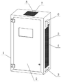
图1为本发明提出的一种高效散热的10KV小型智能化固定开关设备结构示意图;Fig. 1 is a kind of high-efficiency heat dissipation 10KV small intelligent fixed switchgear structure schematic diagram proposed by the present invention;
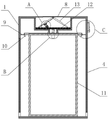
图2为本发明提出的固定开关设备正剖面结构示意图;FIG. 2 is a schematic diagram of the front cross-sectional structure of the fixed switchgear proposed by the present invention;
图3为本发明提出的图2中A处放大结构示意图;Fig. 3 is the enlarged structural schematic diagram of place A in Fig. 2 proposed by the present invention;
图4为本发明提出的图2中B处放大结构示意图;Fig. 4 is the enlarged structural schematic diagram of the place B in Fig. 2 proposed by the present invention;
图5为本发明提出的图2中C处放大结构示意图;Fig. 5 is the enlarged schematic diagram of the structure at C in Fig. 2 proposed by the present invention;
图中:1、外机箱;2、箱体门板;3、排水口;4、散热槽口;5、散热网;6、控制组件;7、过滤网;8、雨水收集口;9、固定架板;10、雾化喷头;11、开关设备主体;12、漂浮板;13、封板;14、红外发射器;15、防水壳体一;16、透光膜一;17、红外接收器;18、防水壳体二;19、透光膜二;20、泵;21、三通管;22、导水管;23、外壳体;24、控制器;25、指示灯;26、喇叭;27、温感器。In the picture: 1. External chassis; 2. Cabinet door; 3. Drainage port; 4. Cooling slot; 5. Cooling net; 6. Control component; 7. Filter net; 8. Rainwater collection port; Board; 10. Atomizing nozzle; 11. Main body of switchgear; 12. Floating plate; 13. Sealing plate; 14. Infrared transmitter; 15. Waterproof shell one; 18. Waterproof shell II; 19. Light-transmitting film II; 20. Pump; 21. Tee pipe; 22. Water conduit; 23. Outer shell; 24. Controller; 25. Indicator light; 26. Horn; 27. temperature sensor.
具体实施方式Detailed ways
下面将结合本发明实施例中的附图,对本发明实施例中的技术方案进行清楚、完整地描述,显然,所描述的实施例仅仅是本发明一部分实施例,而不是全部的实施例。基于本发明中的实施例,本领域普通技术人员在没有做出创造性劳动前提下所获得的所有其他实施例,都属于本发明保护的范围。The technical solutions in the embodiments of the present invention will be clearly and completely described below with reference to the accompanying drawings in the embodiments of the present invention. Obviously, the described embodiments are only a part of the embodiments of the present invention, but not all of the embodiments. Based on the embodiments of the present invention, all other embodiments obtained by those of ordinary skill in the art without creative efforts shall fall within the protection scope of the present invention.
请参阅图1-5,本发明提供一种技术方案:一种高效散热的10KV小型智能化固定开关设备,包括外机箱1,以及固定安装在外机箱1内部的开关设备主体11,开关设备主体11与外机箱1之间形成储热腔,外机箱1的顶部向内凹型形成收集槽,收集槽的顶部开设有用于承接雨水的雨水收集口8,在雨水天气下,雨水通过雨水收集口8进入到收集槽中,进而用于对开关设备主体11降温使用,收集槽两侧对称铰接有用于封堵雨水收集口8的封板13,在雨水集满到设计量后,雨水不能再进入收集槽中,进而保护收集槽内红外发射模块与红外接收模块,左侧封板13的下表面固定安装有发射红外光线的红外发射模块,收集槽的底部容置有能够浮起在雨水液面的漂浮板12,漂浮板12的左侧上表面固定安装有用于接收红外发射模块发出红外光线的红外接收模块,在当漂浮板12处于收集槽底部时,说明收集槽内部雨水量已到警戒位置,而此时,左侧封板13上的红外发射模块与漂浮板12上的红外接收模块正好对齐,从而发出警戒信号,收集槽的底部向内凹陷的汇集槽,汇集槽内固定安装有抽水装置,通过抽水装置抽取汇集槽中的雨水,开关设备主体11中装设有用于监测发热温度的温感器27,外机箱1的右侧外壁上装设有与温感器27电连接的控制组件6,控制组件6与红外接收模块信号连接,通过温感器27实时监测开关设备主体11内温度,当温度过高时,控制组件6发出警报,同时控制抽水装置将雨水抽取并喷向开关设备主体11外壁,对开关设备主体11进行快速降温,而在外机箱1的两侧对称开设有用于散热的散热槽口4,通过散热槽口4散出部分热量,散热槽口4下方的外机箱1上开设有用于排水的排水口3,由排水口3排出污水,带走部分热量。1-5, the present invention provides a technical solution: a 10KV small intelligent fixed switchgear with efficient heat dissipation, including an
为了保护抽水装置不受损坏,在封板13与漂浮板12上装设红外发射模块与红外接收模块,红外发射模块包括防水壳体一15,以及固定安装在防水壳体一15中的红外发射器14,防水壳体一15的下表面开设有用于光线穿出的通孔一,红外接收模块包括防水壳体二18,以及倾斜固定在防水壳体二18中的红外接收器17,防水壳体二18的上表面开设有用于光线进入的通孔二,当收集槽中仍存在雨水时,红外发射模块与红外接收模块尚未对齐,红外接收器17无法接收到红外发射器14发出的红外光线,抽水装置可继续进行抽水降温工作,在当雨水液面低于收集槽底部时,漂浮板12处于收集槽底部,而此时红外发射模块与红外接收模块正好对齐,红外接收器17接收到红外发射器14发出的红外光线后将信号反馈给控制组件6,进而由控制组件6关闭抽水装置。In order to protect the pumping device from damage, an infrared emitting module and an infrared receiving module are installed on the sealing
为了使漂浮板12更易飘起,漂浮板12上密布有多个导水孔,使得雨水能够透过导水孔,进而使漂浮板12始终漂浮在液面上,对红外发射模块与红外接收模块起到有效保护。In order to make the floating
为了对开关设备主体11快速降温,在汇集槽内设置抽水装置,抽水装置包括泵20,泵20的输出端连通有三通管21的一端,三通管21的另外两端连通有导水管22,两个导水管22的另一端固定连接有倾斜朝向开关设备主体11的雾化喷头10,储热腔的腔壁上固定连接有用于固定雾化喷头10的固定架板9,在泵20的抽取下,将雨水沿着导水管22输送至雾化喷头10,在由雾化喷头10雾化后喷向开关设备主体11的外壁,对开关设备主体11进行降温处理。In order to rapidly cool down the
为了防止雨水浸入而损坏红外发射器14与红外接收器17,通孔一中固定设置有透光膜一16,通孔二中固定设置有透光膜二19,防止雨水从通孔中渗入,同时不影响透光性。In order to prevent the intrusion of rainwater from damaging the
为了起到报警效果,在外机箱1上设置控制组件6,控制组件6包括外壳体23,以及安装在外壳体23内部的控制器24,外壳体23的上设置有指示灯25,指示灯25下侧的外壳体23上设置有喇叭26,指示灯25、喇叭26均与控制器24电连接,通过控制器24接受温感器27与红外接收模块的信号,进而通过指示灯25与喇叭26对收集槽雨水存储状态以及设备过热状态进行监测和报警。In order to play an alarming effect, a
为了起到防尘效果,雨水收集口8处固定安装有过滤网7,防止灰尘进入造成管路堵塞,散热槽口4处固定安装有散热网5,避免灰尘进入,保持散热性,外机箱1的前端面铰接有箱体门板2,可通过打开箱体门板2对开关设备主体11进行维修检查。In order to play a dustproof effect, a
本发明的工作原理及使用流程如下:雨水天气时,雨水通过雨水收集口8进入到收集槽中,进而用于对开关设备主体11降温使用,由于收集槽中仍存在雨水,红外发射模块与红外接收模块尚未对齐,红外接收器17无法接收到红外发射器14发出的红外光线,抽水装置能够正常工作;The working principle and use process of the present invention are as follows: in rainy weather, the rainwater enters the collection tank through the
在当开关设备主体11温度过高时,开关设备主体11上的温感器27反馈信号给控制组件6,由控制组件6通过指示灯25与喇叭26发出警报,同时控制泵20将汇集槽中的雨水抽取,使雨水沿着导水管22输送至雾化喷头10,在由雾化喷头10雾化后喷向开关设备主体11的外壁,对开关设备主体11进行降温处理,通过散热槽口4散出部分热量,滴落的污水由排水口3排出,带走部分热量,达到快速降温的目的;When the temperature of the switchgear
当泵20在抽取一段时间后雨水液面逐渐低于收集槽底部时,漂浮板12随着液面的降低而到达收集槽底,而此时封板13上的红外发射模块与漂浮板12上的红外接收模块正好对齐,红外接收器17接收到红外发射器14发出的红外光线后将信号反馈给控制组件6,进而由控制组件6关闭泵20,对泵20进行保护,同时通过指示灯25与喇叭26发出警报,提示需要加水降温。When the water level of the rainwater is gradually lower than the bottom of the collection tank after the
尽管已经示出和描述了本发明的实施例,对于本领域的普通技术人员而言,可以理解在不脱离本发明的原理和精神的情况下可以对这些实施例进行多种变化、修改、替换和变型,本发明的范围由所附权利要求及其等同物限定。Although embodiments of the present invention have been shown and described, it will be understood by those skilled in the art that various changes, modifications, and substitutions can be made in these embodiments without departing from the principle and spirit of the invention and modifications, the scope of the invention is defined by the appended claims and their equivalents.
Claims (7)
Priority Applications (1)
| Application Number | Priority Date | Filing Date | Title |
|---|---|---|---|
| CN202110400478.3A CN113328362B (en) | 2021-04-14 | 2021-04-14 | High-efficient radiating 10KV small-size intelligent fixed switch equipment |
Applications Claiming Priority (1)
| Application Number | Priority Date | Filing Date | Title |
|---|---|---|---|
| CN202110400478.3A CN113328362B (en) | 2021-04-14 | 2021-04-14 | High-efficient radiating 10KV small-size intelligent fixed switch equipment |
Publications (2)
| Publication Number | Publication Date |
|---|---|
| CN113328362A CN113328362A (en) | 2021-08-31 |
| CN113328362B true CN113328362B (en) | 2022-07-01 |
Family
ID=77414953
Family Applications (1)
| Application Number | Title | Priority Date | Filing Date |
|---|---|---|---|
| CN202110400478.3A Active CN113328362B (en) | 2021-04-14 | 2021-04-14 | High-efficient radiating 10KV small-size intelligent fixed switch equipment |
Country Status (1)
| Country | Link |
|---|---|
| CN (1) | CN113328362B (en) |
Families Citing this family (1)
| Publication number | Priority date | Publication date | Assignee | Title |
|---|---|---|---|---|
| CN116247544B (en) * | 2023-03-16 | 2023-10-31 | 无锡市冠云换热器有限公司 | Energy-saving type power equipment cooler |
Citations (6)
| Publication number | Priority date | Publication date | Assignee | Title |
|---|---|---|---|---|
| US6553723B1 (en) * | 1999-09-29 | 2003-04-29 | Gary Alcorn | Rainwater collection and storage system |
| CN103389144A (en) * | 2013-07-26 | 2013-11-13 | 北京建筑大学 | Under-bridge accumulated water depth detection device and intelligent early warning method |
| CN211047736U (en) * | 2019-12-31 | 2020-07-17 | 台州职业技术学院 | Heat radiator for electronic and electrical equipment |
| CN211151197U (en) * | 2019-10-14 | 2020-07-31 | 上海安昂自动化设备有限公司 | Stainless steel distribution box |
| CN212566353U (en) * | 2020-06-17 | 2021-02-19 | 浙江中新电力工程建设有限公司 | Distributed energy management and control equipment based on internet |
| CN212968677U (en) * | 2020-08-13 | 2021-04-13 | 海口佳源泰电气设备有限公司 | Distribution box capable of automatically radiating heat |
-
2021
- 2021-04-14 CN CN202110400478.3A patent/CN113328362B/en active Active
Patent Citations (6)
| Publication number | Priority date | Publication date | Assignee | Title |
|---|---|---|---|---|
| US6553723B1 (en) * | 1999-09-29 | 2003-04-29 | Gary Alcorn | Rainwater collection and storage system |
| CN103389144A (en) * | 2013-07-26 | 2013-11-13 | 北京建筑大学 | Under-bridge accumulated water depth detection device and intelligent early warning method |
| CN211151197U (en) * | 2019-10-14 | 2020-07-31 | 上海安昂自动化设备有限公司 | Stainless steel distribution box |
| CN211047736U (en) * | 2019-12-31 | 2020-07-17 | 台州职业技术学院 | Heat radiator for electronic and electrical equipment |
| CN212566353U (en) * | 2020-06-17 | 2021-02-19 | 浙江中新电力工程建设有限公司 | Distributed energy management and control equipment based on internet |
| CN212968677U (en) * | 2020-08-13 | 2021-04-13 | 海口佳源泰电气设备有限公司 | Distribution box capable of automatically radiating heat |
Also Published As
| Publication number | Publication date |
|---|---|
| CN113328362A (en) | 2021-08-31 |
Similar Documents
| Publication | Publication Date | Title |
|---|---|---|
| CN110661195B (en) | Dampproofing cubical switchboard of heat dissipation | |
| CN207149909U (en) | A kind of anti-condensation anti-theft type ring main unit | |
| CN112638139A (en) | Internet big data server rack | |
| CN108649444A (en) | A kind of multi-chamber metal armouring central switch equipment | |
| CN113328362B (en) | High-efficient radiating 10KV small-size intelligent fixed switch equipment | |
| CN215379683U (en) | Automatic monitoring devices of electronic engineering cabinet | |
| CN210273075U (en) | Outdoor control cabinet for solar power generation | |
| CN215989879U (en) | High-voltage power distribution cabinet with intelligent constant-temperature adjusting and heat dissipation structure | |
| CN205105472U (en) | Synthesize outdoor rack of access type | |
| CN209461881U (en) | A kind of power distribution cabinet of dustproof and waterproof | |
| CN109038281A (en) | A kind of anticreep outdoor intelligent power distribution low-tension switch cabinet with protective effect | |
| CN208674670U (en) | A kind of distribution box that security performance for building is high | |
| CN212210041U (en) | High temperature resistance intelligence cubical switchboard | |
| CN105044415A (en) | Power metering box multiple-protection device | |
| CN210926634U (en) | Safe type high-low voltage power distribution cabinet | |
| CN209709510U (en) | A kind of factory's power distribution cabinet water circulation cooling system | |
| CN112924730A (en) | Intelligent electric meter | |
| CN218374186U (en) | A motor-pumped well type integration intelligent pump station for agricultural irrigation | |
| CN207625168U (en) | A kind of outdoor electricity distribution net low pressure end electric energy compensation device | |
| CN110488883A (en) | Dehumidification Monitoring System Applied to Substation Cable Trench | |
| CN214100576U (en) | Energy-saving box-type fixed alternating-current metal closed ring network switch equipment | |
| CN211879899U (en) | Rain-proof electric distribution box | |
| CN207604069U (en) | A kind of group of switches | |
| CN208522278U (en) | A kind of multi-chamber metal armouring central switch equipment | |
| CN207232220U (en) | A kind of ammeter box with ventilation waterproof structure |
Legal Events
| Date | Code | Title | Description |
|---|---|---|---|
| PB01 | Publication | ||
| PB01 | Publication | ||
| SE01 | Entry into force of request for substantive examination | ||
| SE01 | Entry into force of request for substantive examination | ||
| GR01 | Patent grant | ||
| GR01 | Patent grant | ||
| PE01 | Entry into force of the registration of the contract for pledge of patent right | ||
| PE01 | Entry into force of the registration of the contract for pledge of patent right |
Denomination of invention: A 10KV small intelligent fixed switchgear with efficient heat dissipation Granted publication date: 20220701 Pledgee: Tonglu Zhejiang rural commercial bank Limited by Share Ltd. Pledgor: HANGHZOU SHENGLI ELECTRIC Co.,Ltd. Registration number: Y2025330000634 |