CN113320018A - Cleaning device for concrete mixing structure - Google Patents
Cleaning device for concrete mixing structure Download PDFInfo
- Publication number
- CN113320018A CN113320018A CN202110718935.3A CN202110718935A CN113320018A CN 113320018 A CN113320018 A CN 113320018A CN 202110718935 A CN202110718935 A CN 202110718935A CN 113320018 A CN113320018 A CN 113320018A
- Authority
- CN
- China
- Prior art keywords
- fixedly connected
- box
- concrete mixing
- water
- cleaning device
- Prior art date
- Legal status (The legal status is an assumption and is not a legal conclusion. Google has not performed a legal analysis and makes no representation as to the accuracy of the status listed.)
- Withdrawn
Links
- 238000004140 cleaning Methods 0.000 title claims abstract description 26
- XLYOFNOQVPJJNP-UHFFFAOYSA-N water Substances O XLYOFNOQVPJJNP-UHFFFAOYSA-N 0.000 claims abstract description 53
- 239000007921 spray Substances 0.000 claims abstract description 19
- 238000007790 scraping Methods 0.000 claims description 23
- 239000000463 material Substances 0.000 claims description 16
- 238000007789 sealing Methods 0.000 claims description 11
- 229910001220 stainless steel Inorganic materials 0.000 claims description 3
- 239000010935 stainless steel Substances 0.000 claims description 3
- 238000005406 washing Methods 0.000 claims description 2
- 238000005507 spraying Methods 0.000 abstract description 3
- 238000004519 manufacturing process Methods 0.000 abstract description 2
- 239000002351 wastewater Substances 0.000 description 11
- 230000000694 effects Effects 0.000 description 4
- 239000004575 stone Substances 0.000 description 3
- 238000005299 abrasion Methods 0.000 description 2
- 239000000654 additive Substances 0.000 description 2
- 230000000996 additive effect Effects 0.000 description 2
- 239000002131 composite material Substances 0.000 description 2
- 239000012535 impurity Substances 0.000 description 2
- 229910052500 inorganic mineral Inorganic materials 0.000 description 2
- 239000011707 mineral Substances 0.000 description 2
- 238000011045 prefiltration Methods 0.000 description 2
- 238000011084 recovery Methods 0.000 description 2
- 238000003756 stirring Methods 0.000 description 2
- 230000003044 adaptive effect Effects 0.000 description 1
- 230000004075 alteration Effects 0.000 description 1
- 230000009286 beneficial effect Effects 0.000 description 1
- 238000007599 discharging Methods 0.000 description 1
- 238000001914 filtration Methods 0.000 description 1
- 238000000034 method Methods 0.000 description 1
- 239000000203 mixture Substances 0.000 description 1
- 238000012986 modification Methods 0.000 description 1
- 230000004048 modification Effects 0.000 description 1
- 239000002994 raw material Substances 0.000 description 1
- 239000000126 substance Substances 0.000 description 1
- 238000006467 substitution reaction Methods 0.000 description 1
- 239000002699 waste material Substances 0.000 description 1
Images


Classifications
-
- B—PERFORMING OPERATIONS; TRANSPORTING
- B28—WORKING CEMENT, CLAY, OR STONE
- B28C—PREPARING CLAY; PRODUCING MIXTURES CONTAINING CLAY OR CEMENTITIOUS MATERIAL, e.g. PLASTER
- B28C7/00—Controlling the operation of apparatus for producing mixtures of clay or cement with other substances; Supplying or proportioning the ingredients for mixing clay or cement with other substances; Discharging the mixture
- B28C7/16—Discharge means, e.g. with intermediate storage of fresh concrete
-
- B—PERFORMING OPERATIONS; TRANSPORTING
- B01—PHYSICAL OR CHEMICAL PROCESSES OR APPARATUS IN GENERAL
- B01D—SEPARATION
- B01D29/00—Filters with filtering elements stationary during filtration, e.g. pressure or suction filters, not covered by groups B01D24/00 - B01D27/00; Filtering elements therefor
- B01D29/01—Filters with filtering elements stationary during filtration, e.g. pressure or suction filters, not covered by groups B01D24/00 - B01D27/00; Filtering elements therefor with flat filtering elements
- B01D29/03—Filters with filtering elements stationary during filtration, e.g. pressure or suction filters, not covered by groups B01D24/00 - B01D27/00; Filtering elements therefor with flat filtering elements self-supporting
-
- B—PERFORMING OPERATIONS; TRANSPORTING
- B08—CLEANING
- B08B—CLEANING IN GENERAL; PREVENTION OF FOULING IN GENERAL
- B08B9/00—Cleaning hollow articles by methods or apparatus specially adapted thereto
- B08B9/08—Cleaning containers, e.g. tanks
- B08B9/087—Cleaning containers, e.g. tanks by methods involving the use of tools, e.g. brushes, scrapers
-
- B—PERFORMING OPERATIONS; TRANSPORTING
- B08—CLEANING
- B08B—CLEANING IN GENERAL; PREVENTION OF FOULING IN GENERAL
- B08B9/00—Cleaning hollow articles by methods or apparatus specially adapted thereto
- B08B9/08—Cleaning containers, e.g. tanks
- B08B9/093—Cleaning containers, e.g. tanks by the force of jets or sprays
Landscapes
- Engineering & Computer Science (AREA)
- Mechanical Engineering (AREA)
- Chemical & Material Sciences (AREA)
- Chemical Kinetics & Catalysis (AREA)
- Dispersion Chemistry (AREA)
- Preparation Of Clay, And Manufacture Of Mixtures Containing Clay Or Cement (AREA)
Abstract
The invention belongs to the field of concrete production, and particularly relates to a cleaning device for a concrete mixing structure, which comprises a box body, wherein the bottom of the box body is provided with a discharge hole, the upper end of the box body is connected with a box cover through threads, a water adding pipe is fixedly connected in the box cover, a valve is arranged on the water adding pipe, the lower end of the water adding pipe is fixedly connected with a ring box, and the outer side of the ring box is fixedly connected with a spray head; the upper end of the box cover is fixedly provided with a cylinder, the lower end of a cylinder rod of the cylinder is fixedly connected with a connecting column, the lower end of the connecting column is fixedly connected with a connecting rod, and the lower end of the connecting rod is fixedly connected with a chassis. The invention designs the structures of the water feeding pipe, the water delivery hose, the valve, the ring box, the spray head and the like to form the water spraying device, can spray water to clean the interior of the box body, and the spray heads are distributed annularly, can spray in all directions of the interior of the box body, can be cleaned only by opening the valve, and is convenient and rapid to use, thereby improving the cleaning efficiency.
Description
Technical Field
The invention relates to the technical field of concrete production, in particular to a cleaning device for a concrete mixing structure.
Background
The concrete is a mixture prepared by mixing a cementing material (organic, inorganic or organic-inorganic composite), granular aggregate, water, a chemical additive and a mineral admixture which need to be added according to a proper proportion, or a composite material (generally a cementing material, water, fine aggregate and coarse aggregate which need to be added with the additive and the mineral admixture according to a proper proportion) with an aggregate structure after hardening.
When producing concrete, a stirring device is mainly adopted for stirring. But current agitating unit is very inconvenient when wasing, and agitating unit is difficult to carry out perpendicular unloading moreover, leads to arranging the material inconvenient, and the cleaning performance is relatively poor when wasing its inside, is difficult to obtain good washing, and when wasing, waste water direct discharge has also led to the waste of water resource, is difficult to retrieve and recycles.
Disclosure of Invention
The invention aims to provide a cleaning device for a concrete mixing structure, which solves the problems of inconvenient cleaning, inconvenient discharge, poor cleaning effect, difficult recovery of waste water and the like of the existing concrete mixing device.
In order to achieve the purpose, the invention provides the following technical scheme: the cleaning device for the concrete mixing structure comprises a box body, wherein a discharge hole is formed in the bottom of the box body, the upper end of the box body is connected with a box cover through threads, a water feeding pipe is fixedly connected into the box cover, a valve is installed on the water feeding pipe, the lower end of the water feeding pipe is fixedly connected with a ring box, and a spray head is fixedly connected to the outer side of the ring box;
the upper end of the box cover is fixedly provided with an air cylinder, the lower end of an air cylinder rod of the air cylinder is fixedly connected with a connecting column, the lower end of the connecting column is fixedly connected with a connecting rod, the lower end of the connecting rod is fixedly connected with a chassis, the lower end of the chassis is bonded with a sealing gasket, and the lower end of the sealing gasket is in contact with the bottom of the inner side of the box body;
a rotating sleeve is fixedly connected to the outer side of the connecting column, a driven gear is fixedly connected to the outer side of the rotating sleeve, a driving gear is meshed with the right side of the driven gear, a motor is fixedly mounted at the upper end of the box cover, and a driving gear is fixedly mounted at the lower end of a rotating shaft of the motor;
the outer side of the rotating sleeve is fixedly connected with a supporting rod, the outer side of the supporting rod is connected with a connecting sleeve in a sliding mode, a spring is arranged in the connecting sleeve, the tail end of the connecting sleeve is fixedly connected with a supporting strip, and a scraping strip is bonded on the surface of the supporting strip;
the water tank is characterized in that a supporting seat is fixedly connected to the bottom of the outer side of the tank body, a supporting frame is fixedly connected to the lower end of the supporting seat, a base is fixedly connected to the lower end of the supporting frame, a water collecting tank and a flow channel are formed in the inner side of the base, a connector is connected to the flow channel through threads, and a drainage hose is sleeved on the outer side of the connector.
Preferably, the upper end of the box cover is provided with a feed inlet, and the upper end of the box cover is fixedly connected with a feed hopper.
Preferably, the middle part of the box cover is provided with a through groove, and an air cylinder rod is connected in the through groove in a sliding manner.
Preferably, the box cover is provided with a through hole, and a rotating shaft is rotatably connected in the through hole.
Preferably, the number of the spray heads is multiple, and the multiple spray heads are arranged in a ring-shaped array in the ring box.
Preferably, the upper end of the water adding pipe is sleeved with a water delivery hose, and a first clamp is fixedly mounted on the outer side of the water delivery hose.
Preferably, one end of the spring is in contact with the supporting rod, and the other end of the supporting rod is in contact with the supporting strip.
Preferably, the scraping strip is in contact with the inner wall of the box body and is made of a rubber material, a connecting block is arranged on the surface of the scraping strip, and the connecting block is embedded into the supporting bar.
Preferably, the mesh plate is of a porous hollow structure, convex ribs are arranged at the upper end of the mesh plate, and the mesh plate is made of stainless steel materials.
Preferably, the outside fixed mounting of drainage hose has the second clamp, the upper end embedding of base has the mesh board.
Compared with the prior art, the invention has the following beneficial effects:
1. the invention designs the structures of the water feeding pipe, the water delivery hose, the valve, the ring box, the spray head and the like to form the water spraying device, can spray water to clean the interior of the box body, and the spray heads are distributed annularly, can spray in all directions of the interior of the box body, can be cleaned only by opening the valve, and is convenient and rapid to use, thereby improving the cleaning efficiency.
2. According to the invention, the cylinder is arranged on the box cover, the connecting column, the connecting rod, the chassis and the sealing gasket are sequentially designed at the lower end of the cylinder rod of the cylinder, when material discharge is required, the cylinder rod of the cylinder can drive the sealing gasket at the bottom to move upwards only by starting the cylinder, the material discharge port at the bottom is opened for vertical material discharge, and the material discharge is convenient and rapid.
3. The invention designs the driven gear, the rotating sleeve, the supporting rod, the connecting sleeve, the spring, the supporting strip, the scraping strip and other parts to form the rotating mechanism, and the rotating mechanism is driven by the motor, the rotating shaft and the driving gear, so that the scraping strip can be driven to rotate during cleaning, the impurities can be scraped from the inner wall of the box body, the cleaning effect is better, and the residual concrete is eliminated.
4. According to the invention, the connecting sleeve is connected with the supporting rod in a sliding manner, and the design of the spring is adopted, so that the scraping strip can be adapted to eliminate the fit error between the scraping strip and the box body, the poor scraping effect caused by poor contact can be avoided, and the scraping strip is made of rubber materials and has small abrasion to the box body.
5. According to the invention, through designing the structures of the base, the water collecting tank, the flow channel, the joint, the drainage hose, the filter screen plate and the like, the filtering and water collecting device can be formed to collect and filter the wastewater, so that the wastewater is recovered, the wastewater can be recycled, and the water resource is saved.
Drawings
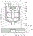
FIG. 1 is a schematic structural view of the present invention;
FIG. 2 is an enlarged view of the portion A of FIG. 1 according to the present invention;
FIG. 3 is an enlarged view of the portion B of FIG. 1 according to the present invention;
FIG. 4 is a top view of the driven gear of FIG. 1 in accordance with the present invention;
FIG. 5 is a top plan view of the ring box of FIG. 1 in accordance with the present invention;
fig. 6 is a top view of the base of fig. 1 in accordance with the present invention.
In the figure: 1. a box body; 2. a discharge outlet; 3. a box cover; 4. a feed inlet; 5. a hopper; 6. a through groove; 7. a through hole; 8. a water feeding pipe; 9. a valve; 10. a water delivery hose; 11. a first clamp; 12. a ring box; 13. a spray head; 14. a cylinder; 15. a cylinder rod; 16. connecting columns; 17. a connecting rod; 18. a chassis; 19. a gasket; 20. rotating the sleeve; 21. a driven gear; 22. an electric motor; 23. a rotating shaft; 24. a drive gear; 25. a support bar; 26. connecting sleeves; 27. a spring; 28. a supporting strip; 29. scraping the strips; 30. connecting blocks; 31. a supporting seat; 32. a support frame; 33. a base; 34. a water collection tank; 35. a flow channel; 36. a joint; 37. a drain hose; 38. a second clamp; 39. a mesh plate; 40. and (5) convex ribs.
Detailed Description
The technical solutions in the embodiments of the present invention will be clearly and completely described below with reference to the drawings in the embodiments of the present invention, and it is obvious that the described embodiments are only a part of the embodiments of the present invention, and not all of the embodiments. All other embodiments, which can be derived by a person skilled in the art from the embodiments given herein without making any creative effort, shall fall within the protection scope of the present invention.
Examples
Referring to fig. 1-6, the cleaning device for the concrete mixing structure comprises a box body 1, wherein a discharge port 2 is arranged at the bottom of the box body 1, a box cover 3 is connected to the upper end of the box body 1 through threads, a water feeding pipe 8 is fixedly connected to the inside of the box cover 3, a valve 9 is arranged on the water feeding pipe 8, a ring box 12 is fixedly connected to the lower end of the water feeding pipe 8, and a spray head 13 is fixedly connected to the outer side of the ring box 12;
the upper end of the box cover 3 is fixedly provided with a cylinder 14, the model of the cylinder is SC series standard cylinders, and belongs to the prior art, the lower end of a cylinder rod 15 of the cylinder 14 is fixedly connected with a connecting column 16, the lower end of the connecting column 16 is fixedly connected with a connecting rod 17, the lower end of the connecting rod 17 is fixedly connected with a chassis 18, the lower end of the chassis 18 is bonded with a sealing gasket 19, the lower end of the sealing gasket 19 is contacted with the inner side bottom of the box body 1, the sealing gasket 19 is made of rubber materials, and the bottom of the box body 1 can be sealed through the design of the sealing gasket 19;
the outer side of the connecting column 16 is fixedly connected with a rotating sleeve 20, the outer side of the rotating sleeve 20 is fixedly connected with a driven gear 21, the right side of the driven gear 21 is meshed with a driving gear 24, the upper end of the box cover 3 is fixedly provided with a motor 22 with the model number of YE2, and the lower end of a rotating shaft 23 of the motor 22 is fixedly provided with the driving gear 24;
the outer side of the rotating sleeve 20 is fixedly connected with a supporting rod 25, the outer side of the supporting rod 25 is connected with a connecting sleeve 26 in a sliding manner, a spring 27 is arranged in the connecting sleeve 26, the tail end of the connecting sleeve 26 is fixedly connected with a supporting strip 28, and the surface of the supporting strip 28 is bonded with a scraping strip 29;
the outer side bottom fixedly connected with supporting seat 31 of box 1, the lower extreme fixedly connected with support frame 32 of supporting seat 31, the lower extreme fixedly connected with base 33 of support frame 32, water catch bowl 34 and runner 35 have been seted up to the inboard of base 33, have joint 36 through threaded connection in the runner 35, and drainage hose 37 has been cup jointed in the outside of joint 36.
Referring to fig. 1, a feed inlet 4 is formed at the upper end of the box cover 3, and a hopper 5 is fixedly connected to the upper end of the box cover 3. Through the design of the feed inlet 4 and the feed hopper 5, raw materials can be added into the box body 1.
Referring to fig. 2, a through groove 6 is formed in the middle of the box cover 3, and an air cylinder rod 15 is slidably connected in the through groove 6. Through the design of through slot 6, a moving space is provided for cylinder rod 15.
Referring to fig. 2, a through hole 7 is formed in the case cover 3, and a rotating shaft 23 is rotatably connected to the through hole 7. Through the design of the through hole 7, a rotation space is provided for the rotation shaft 23.
Referring to fig. 5, the number of the nozzles 13 is plural, and the plural nozzles 13 are arranged in a ring-shaped array in the ring box 12. By annularly distributing the plurality of nozzles 13, water can be sprayed in various directions inside the tank 1.
Referring to fig. 1, a water hose 10 is sleeved on an upper end of the water feeding pipe 8, and a first clamp 11 is fixedly installed on an outer side of the water hose 10. The water hose 10 is connected with a high-pressure water pipe of a workshop and can provide high-pressure water.
Referring to fig. 3, one end of the spring 27 contacts the support bar 25, and the other end of the support bar 25 contacts the support bar 28. The spring 27 has an elastic force and can support the support strip 28.
Referring to fig. 3, the scraping bar 29 is in contact with the inner wall of the casing 1, the scraping bar 29 is made of rubber material, the surface of the scraping bar 29 is provided with a connecting block 30, and the connecting block 30 is embedded in the supporting bar 28. By making the wiper strip 29 of a rubber material, less wear is experienced by the housing 1.
Referring to fig. 1 and 6, the mesh plate 39 is a porous and hollow structure, the upper end of the mesh plate 39 is provided with a rib 40, and the mesh plate 39 is made of stainless steel. Through the design of mesh plate 39, can carry out prefilter to the concrete, avoid the stone to get into in base 33.
Referring to fig. 1, a second clamp 38 is fixedly installed at an outer side of the drain hose 37, and a mesh plate 39 is embedded in an upper end of the base 33. The drain hose 37 is fixedly attached to the joint 36 by the attachment of the second clip 38.
The specific implementation process of the invention is as follows: when the interior of the box body 1 needs to be cleaned, the valve 9 is opened, the water delivery hose 10 delivers water to the water feeding pipe 8, then water flows enter the ring box 12 and is sprayed out through the spray heads 13, and as the spray heads 13 are arranged in a plurality and are arranged in an annular array, water spraying cleaning work can be carried out in all directions;
during cleaning, the motor 22 is started, the rotating shaft 23 of the motor 22 drives the driving gear 24 to rotate, the driving gear 24 drives the driven gear 21 to rotate, the driven gear 21 drives the rotating sleeve 20 to rotate, the rotating sleeve 20 drives the supporting rod 25 to rotate, the supporting rod 25 drives the supporting bar 28 to rotate, the supporting bar 28 drives the scraping bar 29 to rotate, and the scraping bar 29 can carry out impurity scraping work on the inner wall of the box body 1 to remove attached concrete residues;
through the design that the connecting sleeve 26 is connected with the supporting rod 25 in a sliding mode and the spring 27 is installed, the scraping strip 29 can be adaptive to eliminate the matching error between the scraping strip and the box body 1, poor scraping effect caused by poor contact can be avoided, and the scraping strip 29 is made of rubber materials and has small abrasion to the box body 1;
during cleaning, the air cylinder 14 is started, the air cylinder rod 15 of the air cylinder 14 moves upwards, the air cylinder rod 15 drives the connecting column 16 to move upwards, the connecting column 16 drives the connecting rod 17 to move upwards, the connecting rod 17 drives the base plate 18 to move upwards, the base plate 18 drives the sealing gasket 19 to move upwards, the discharge opening 2 at the bottom is opened, waste water can be discharged through the discharge opening 2, and discharging is convenient and rapid;
waste water discharges the back, can get into the water catch bowl 34 through mesh plate 39 on the base 33 in, waste water passes through mesh plate 39 prefilter, can filter out the stone, and the stone is recoverable recycles, and waste water gets into the water catch bowl 34 after, then flows into joint 36 through runner 35, then discharges through drainage hose 37, discharges waste water to appointed collecting region, carries out the recovery of waste water.
Although embodiments of the present invention have been shown and described, it will be appreciated by those skilled in the art that changes, modifications, substitutions and alterations can be made in these embodiments without departing from the principles and spirit of the invention, the scope of which is defined in the appended claims and their equivalents.
Claims (10)
1. Washing unit for concrete mixing structure, including box (1), its characterized in that: a discharge outlet (2) is formed in the bottom of the box body (1), the upper end of the box body (1) is connected with a box cover (3) through threads, a water feeding pipe (8) is fixedly connected in the box cover (3), a valve (9) is installed on the water feeding pipe (8), the lower end of the water feeding pipe (8) is fixedly connected with a ring box (12), and a spray head (13) is fixedly connected to the outer side of the ring box (12);
an air cylinder (14) is fixedly mounted at the upper end of the box cover (3), a connecting column (16) is fixedly connected to the lower end of an air cylinder rod (15) of the air cylinder (14), a connecting rod (17) is fixedly connected to the lower end of the connecting column (16), a chassis (18) is fixedly connected to the lower end of the connecting rod (17), a sealing gasket (19) is bonded to the lower end of the chassis (18), and the lower end of the sealing gasket (19) is in contact with the bottom of the inner side of the box body (1);
a rotating sleeve (20) is fixedly connected to the outer side of the connecting column (16), a driven gear (21) is fixedly connected to the outer side of the rotating sleeve (20), a driving gear (24) is meshed with the right side of the driven gear (21), a motor (22) is fixedly mounted at the upper end of the box cover (3), and a driving gear (24) is fixedly mounted at the lower end of a rotating shaft (23) of the motor (22);
the outer side of the rotating sleeve (20) is fixedly connected with a supporting rod (25), the outer side of the supporting rod (25) is connected with a connecting sleeve (26) in a sliding mode, a spring (27) is installed inside the connecting sleeve (26), the tail end of the connecting sleeve (26) is fixedly connected with a supporting strip (28), and a scraping strip (29) is bonded to the surface of the supporting strip (28);
the outer side bottom fixedly connected with supporting seat (31) of box (1), the lower extreme fixedly connected with support frame (32) of supporting seat (31), lower extreme fixedly connected with base (33) of support frame (32), water catch bowl (34) and runner (35) have been seted up to the inboard of base (33), there are joint (36) through threaded connection in runner (35), drainage hose (37) have been cup jointed in the outside of joint (36).
2. The concrete mixing structure cleaning device according to claim 1, wherein: a feeding hole (4) is formed in the upper end of the box cover (3), and a feeding hopper (5) is fixedly connected to the upper end of the box cover (3).
3. The concrete mixing structure cleaning device according to claim 1, wherein: a through groove (6) is formed in the middle of the box cover (3), and a cylinder rod (15) is connected in the through groove (6) in a sliding mode.
4. The concrete mixing structure cleaning device according to claim 1, wherein: a through hole (7) is formed in the box cover (3), and a rotating shaft (23) is rotatably connected in the through hole (7).
5. The concrete mixing structure cleaning device according to claim 1, wherein: the number of the spray heads (13) is multiple, and the spray heads (13) are arranged in an annular array in the annular box (12).
6. The concrete mixing structure cleaning device according to claim 1, wherein: the upper end of the water adding pipe (8) is sleeved with a water delivery hose (10), and a first clamp (11) is fixedly mounted on the outer side of the water delivery hose (10).
7. The concrete mixing structure cleaning device according to claim 1, wherein: one end of the spring (27) is in contact with the supporting rod (25), and the other end of the supporting rod (25) is in contact connection with a supporting strip (28).
8. The concrete mixing structure cleaning device according to claim 1, wherein: scrape the inner wall contact of strip (29) and box (1), scrape strip (29) and make by rubber materials, the surface of scraping strip (29) is provided with connecting block (30), in connecting block (30) embedding support bar (28).
9. The concrete mixing structure cleaning device according to claim 1, wherein: the mesh plate (39) is of a porous hollow structure, convex ribs (40) are arranged at the upper end of the mesh plate (39), and the mesh plate (39) is made of stainless steel materials.
10. The concrete mixing structure cleaning device according to claim 1, wherein: the outside fixed mounting of drainage hose (37) has second clamp (38), the upper end embedding of base (33) has mesh board (39).
Priority Applications (1)
| Application Number | Priority Date | Filing Date | Title |
|---|---|---|---|
| CN202110718935.3A CN113320018A (en) | 2021-06-28 | 2021-06-28 | Cleaning device for concrete mixing structure |
Applications Claiming Priority (1)
| Application Number | Priority Date | Filing Date | Title |
|---|---|---|---|
| CN202110718935.3A CN113320018A (en) | 2021-06-28 | 2021-06-28 | Cleaning device for concrete mixing structure |
Publications (1)
| Publication Number | Publication Date |
|---|---|
| CN113320018A true CN113320018A (en) | 2021-08-31 |
Family
ID=77425015
Family Applications (1)
| Application Number | Title | Priority Date | Filing Date |
|---|---|---|---|
| CN202110718935.3A Withdrawn CN113320018A (en) | 2021-06-28 | 2021-06-28 | Cleaning device for concrete mixing structure |
Country Status (1)
| Country | Link |
|---|---|
| CN (1) | CN113320018A (en) |
Cited By (2)
| Publication number | Priority date | Publication date | Assignee | Title |
|---|---|---|---|---|
| CN113997422A (en) * | 2021-11-22 | 2022-02-01 | 开封市千坊混凝土制品有限公司 | Premixing equipment for concrete production and processing |
| CN114620361A (en) * | 2022-03-17 | 2022-06-14 | 杰维工业设备(长沙)有限公司 | Storage device capable of preventing slurry from solidifying |
-
2021
- 2021-06-28 CN CN202110718935.3A patent/CN113320018A/en not_active Withdrawn
Cited By (3)
| Publication number | Priority date | Publication date | Assignee | Title |
|---|---|---|---|---|
| CN113997422A (en) * | 2021-11-22 | 2022-02-01 | 开封市千坊混凝土制品有限公司 | Premixing equipment for concrete production and processing |
| CN114620361A (en) * | 2022-03-17 | 2022-06-14 | 杰维工业设备(长沙)有限公司 | Storage device capable of preventing slurry from solidifying |
| CN114620361B (en) * | 2022-03-17 | 2023-08-25 | 杰维工业设备(长沙)有限公司 | Storage device capable of preventing slurry from solidifying |
Similar Documents
| Publication | Publication Date | Title |
|---|---|---|
| CN113320018A (en) | Cleaning device for concrete mixing structure | |
| CN114160480B (en) | Sand-powder separation equipment for concrete and method thereof | |
| CN214940901U (en) | Drainage device for construction | |
| CN210336376U (en) | Concrete curing box | |
| CN112246007A (en) | Desanding and purifying equipment for constructional engineering | |
| CN110918436A (en) | Separating system of concrete cleaning roller separator | |
| CN217092283U (en) | Solid-liquid separator with automatic cleaning function | |
| CN214924805U (en) | Recyclable polyurethane screen cutting device with clean table top | |
| CN218309563U (en) | Energy-saving vibration grit belt cleaning device | |
| CN211917267U (en) | Concrete mixer convenient to clearance | |
| CN210278380U (en) | Sand washer and continuous active sand filter | |
| CN217043762U (en) | Concrete waste recycling equipment of make full use of resource | |
| CN219185987U (en) | Wet process production mechanism sand water resource cyclic utilization device | |
| CN219043512U (en) | Diesel engine cylinder fuel injector cleaning device capable of preventing filter screen from being blocked | |
| CN216857009U (en) | Spiral sand washer with water circulation | |
| CN215656669U (en) | Melon seed piece cleaning equipment that paves that cleaning performance is good | |
| CN213527909U (en) | Glass fiber reinforced plastic desulfurization dust collector | |
| CN220072726U (en) | Diamond miropowder beaker belt cleaning device | |
| CN218223745U (en) | Oil tank high pressure spray rinsing equipment capable of recycling water resources | |
| CN217487576U (en) | Bean cleaning equipment | |
| CN219541051U (en) | Pyrophyllite raw material ash removal device | |
| CN216986938U (en) | Raw material spraying dust removal equipment for preparing asphalt pavement material | |
| CN217829645U (en) | Production environmental protection is stirring dispersion equipment for water based paint | |
| CN214523721U (en) | Construction vehicle belt cleaning device | |
| CN216068575U (en) | Extrusion device is used in aerogel production |
Legal Events
| Date | Code | Title | Description |
|---|---|---|---|
| PB01 | Publication | ||
| PB01 | Publication | ||
| SE01 | Entry into force of request for substantive examination | ||
| SE01 | Entry into force of request for substantive examination | ||
| WW01 | Invention patent application withdrawn after publication | ||
| WW01 | Invention patent application withdrawn after publication |
Application publication date: 20210831 |