CN113304831B - Production device of honey powder cake - Google Patents
Production device of honey powder cake Download PDFInfo
- Publication number
- CN113304831B CN113304831B CN202110557454.9A CN202110557454A CN113304831B CN 113304831 B CN113304831 B CN 113304831B CN 202110557454 A CN202110557454 A CN 202110557454A CN 113304831 B CN113304831 B CN 113304831B
- Authority
- CN
- China
- Prior art keywords
- plate
- motor
- fixedly arranged
- bin
- array
- Prior art date
- Legal status (The legal status is an assumption and is not a legal conclusion. Google has not performed a legal analysis and makes no representation as to the accuracy of the status listed.)
- Active
Links
Images


Classifications
-
- B—PERFORMING OPERATIONS; TRANSPORTING
- B02—CRUSHING, PULVERISING, OR DISINTEGRATING; PREPARATORY TREATMENT OF GRAIN FOR MILLING
- B02C—CRUSHING, PULVERISING, OR DISINTEGRATING IN GENERAL; MILLING GRAIN
- B02C17/00—Disintegrating by tumbling mills, i.e. mills having a container charged with the material to be disintegrated with or without special disintegrating members such as pebbles or balls
- B02C17/16—Mills in which a fixed container houses stirring means tumbling the charge
- B02C17/163—Stirring means
-
- B—PERFORMING OPERATIONS; TRANSPORTING
- B01—PHYSICAL OR CHEMICAL PROCESSES OR APPARATUS IN GENERAL
- B01D—SEPARATION
- B01D1/00—Evaporating
- B01D1/0011—Heating features
- B01D1/0017—Use of electrical or wave energy
-
- B—PERFORMING OPERATIONS; TRANSPORTING
- B01—PHYSICAL OR CHEMICAL PROCESSES OR APPARATUS IN GENERAL
- B01F—MIXING, e.g. DISSOLVING, EMULSIFYING OR DISPERSING
- B01F21/00—Dissolving
- B01F21/10—Dissolving using driven stirrers
-
- B—PERFORMING OPERATIONS; TRANSPORTING
- B01—PHYSICAL OR CHEMICAL PROCESSES OR APPARATUS IN GENERAL
- B01F—MIXING, e.g. DISSOLVING, EMULSIFYING OR DISPERSING
- B01F27/00—Mixers with rotary stirring devices in fixed receptacles; Kneaders
- B01F27/60—Mixers with rotary stirring devices in fixed receptacles; Kneaders with stirrers rotating about a horizontal or inclined axis
- B01F27/70—Mixers with rotary stirring devices in fixed receptacles; Kneaders with stirrers rotating about a horizontal or inclined axis with paddles, blades or arms
-
- B—PERFORMING OPERATIONS; TRANSPORTING
- B01—PHYSICAL OR CHEMICAL PROCESSES OR APPARATUS IN GENERAL
- B01F—MIXING, e.g. DISSOLVING, EMULSIFYING OR DISPERSING
- B01F33/00—Other mixers; Mixing plants; Combinations of mixers
- B01F33/80—Mixing plants; Combinations of mixers
- B01F33/83—Mixing plants specially adapted for mixing in combination with disintegrating operations
- B01F33/831—Devices with consecutive working receptacles, e.g. with two intermeshing tools in one of the receptacles
-
- B—PERFORMING OPERATIONS; TRANSPORTING
- B01—PHYSICAL OR CHEMICAL PROCESSES OR APPARATUS IN GENERAL
- B01F—MIXING, e.g. DISSOLVING, EMULSIFYING OR DISPERSING
- B01F35/00—Accessories for mixers; Auxiliary operations or auxiliary devices; Parts or details of general application
- B01F35/90—Heating or cooling systems
- B01F35/93—Heating or cooling systems arranged inside the receptacle
-
- B—PERFORMING OPERATIONS; TRANSPORTING
- B02—CRUSHING, PULVERISING, OR DISINTEGRATING; PREPARATORY TREATMENT OF GRAIN FOR MILLING
- B02C—CRUSHING, PULVERISING, OR DISINTEGRATING IN GENERAL; MILLING GRAIN
- B02C17/00—Disintegrating by tumbling mills, i.e. mills having a container charged with the material to be disintegrated with or without special disintegrating members such as pebbles or balls
- B02C17/18—Details
- B02C17/183—Feeding or discharging devices
-
- B—PERFORMING OPERATIONS; TRANSPORTING
- B02—CRUSHING, PULVERISING, OR DISINTEGRATING; PREPARATORY TREATMENT OF GRAIN FOR MILLING
- B02C—CRUSHING, PULVERISING, OR DISINTEGRATING IN GENERAL; MILLING GRAIN
- B02C17/00—Disintegrating by tumbling mills, i.e. mills having a container charged with the material to be disintegrated with or without special disintegrating members such as pebbles or balls
- B02C17/18—Details
- B02C17/24—Driving mechanisms
-
- B—PERFORMING OPERATIONS; TRANSPORTING
- B01—PHYSICAL OR CHEMICAL PROCESSES OR APPARATUS IN GENERAL
- B01F—MIXING, e.g. DISSOLVING, EMULSIFYING OR DISPERSING
- B01F35/00—Accessories for mixers; Auxiliary operations or auxiliary devices; Parts or details of general application
- B01F35/90—Heating or cooling systems
- B01F2035/99—Heating
-
- B—PERFORMING OPERATIONS; TRANSPORTING
- B01—PHYSICAL OR CHEMICAL PROCESSES OR APPARATUS IN GENERAL
- B01F—MIXING, e.g. DISSOLVING, EMULSIFYING OR DISPERSING
- B01F2101/00—Mixing characterised by the nature of the mixed materials or by the application field
- B01F2101/21—Mixing of ingredients for cosmetic or perfume compositions
-
- Y—GENERAL TAGGING OF NEW TECHNOLOGICAL DEVELOPMENTS; GENERAL TAGGING OF CROSS-SECTIONAL TECHNOLOGIES SPANNING OVER SEVERAL SECTIONS OF THE IPC; TECHNICAL SUBJECTS COVERED BY FORMER USPC CROSS-REFERENCE ART COLLECTIONS [XRACs] AND DIGESTS
- Y02—TECHNOLOGIES OR APPLICATIONS FOR MITIGATION OR ADAPTATION AGAINST CLIMATE CHANGE
- Y02A—TECHNOLOGIES FOR ADAPTATION TO CLIMATE CHANGE
- Y02A40/00—Adaptation technologies in agriculture, forestry, livestock or agroalimentary production
- Y02A40/90—Adaptation technologies in agriculture, forestry, livestock or agroalimentary production in food processing or handling, e.g. food conservation
Landscapes
- Chemical & Material Sciences (AREA)
- Chemical Kinetics & Catalysis (AREA)
- Engineering & Computer Science (AREA)
- Food Science & Technology (AREA)
- Crushing And Pulverization Processes (AREA)
Abstract
The invention discloses a production device of honey and flour cakes. The raw material crushing module comprises a supporting table, a mounting plate, a crushing tank, a first connecting frame, a second connecting frame, a guide rod, a first screw rod, a first cylinder, a first rotating blade, a second motor and a third motor. The invention can fully crush and process various raw materials at the same time, can ensure that the raw materials can be crushed into fine particles without influencing subsequent processing, improves the production efficiency, and has stronger practicability and economical efficiency. The problem of among the prior art honey powder cake production and processing process complicated, because the raw materials is various, need mix processing to its raw materials in proper order usually, need carry out the transportation of a lot of production lines to the raw materials of distribution processing by the manual work after the substep processing usually is solved for holistic machining efficiency is slow, and process time is long, very consumes producers physical power moreover is solved.
Description
Technical Field
The invention belongs to the field of cosmetic processing, and particularly relates to a production device of a honey powder cake.
Background
With the continuous progress of the times, people are pursuing higher quality substance life, wherein more and more people are pursuing beauty, so that the daily chemical industry is rapidly developed in the current times.
The loose powder is one of face beautifying cosmetics, and is named as ' fixed make-up powder ', honey powder ' and ' loose white powder ' in the technical name. The loose powder is a powder product which does not contain oil and is prepared from powder raw materials. Is mainly used for applying after foundation emulsion or foundation cream, mostly for cosmetic after-finishing and make-up, adjusting skin tone, preventing greasy skin from being excessively smooth or excessively sticky, showing dull but transparent skin color, reducing sweat and sebum, enhancing persistence of cosmetics, and producing soft, fluffy skin feel.
The honey powder cake is a cake-shaped solid cosmetic product formed by mixing and pressing various powder raw materials (including pigment) such as honey powder and the like and an adhesive (grease component), the traditional honey powder cake is complex in production and processing procedures, the raw materials are generally required to be sequentially mixed and processed due to the diversity of the raw materials, and the raw materials which are distributed and processed are generally required to be manually transported for multiple production lines after being processed step by step, so that the overall processing efficiency is low, the processing time is long, the physical strength of production personnel is greatly consumed, therefore, the honey powder cake production and processing device is designed to have high overall uniformity without manual participation, and the device for automatically finishing the honey powder cake production and processing is in accordance with the actual needs.
Aiming at the problems, a production device of the honey powder cake is designed.
Disclosure of Invention
Aiming at the defects of the prior art, the invention aims to provide a honey powder cake production device, which solves the problems that in the prior art, honey powder cakes are complex in production and processing procedures, raw materials are required to be sequentially mixed and processed due to the diversity of the raw materials, and the raw materials which are distributed and processed are required to be manually transported by multiple production lines after being processed step by step, so that the overall processing efficiency is low, the processing time is long, and the physical strength of production personnel is very high.
The purpose of the invention can be realized by the following technical scheme:
the utility model provides a production device of sweet powder cake, includes the backup pad, the fixed support column that is equipped with array distribution of lower extreme of backup pad, be equipped with the conveyer belt under the backup pad, the side of conveyer belt is equipped with the first motor that the drive conveyer belt conveyed.
The fixed spout that is equipped with the symmetry and sets up in the upper end of backup pad, be equipped with the connecting plate directly over the backup pad, the fixed raw materials crushing module that is equipped with the array distribution in upper end of connecting plate, the fixed evaporation storehouse that dissolves that is equipped with in upper end of backup pad, be equipped with the fixed plate directly over the evaporation storehouse that dissolves, the fixed telescoping cylinder that is equipped with in upper end of fixed plate.
The raw materials crushing module includes a supporting table, the fixed connecting leg that is equipped with array distribution of lower extreme of supporting table, the lower extreme of connecting leg and the upper end fixed connection of connecting plate, the fixed spliced pole that is equipped with of lower extreme of supporting table, the fixed mounting panel that is equipped with of lower extreme of spliced pole, the fixed broken jar that is equipped with in upper end of mounting panel, broken jar run through the supporting table to with supporting table fixed connection.
Further, the fixed first link and the second link that are equipped with the symmetry and set up in the upper end of brace table, be equipped with the first lead screw that rotates the connection in the first link, be equipped with fixed connection's guide arm in the second link, first lead screw and guide arm run through the elevating platform, first lead screw and elevating platform screw-thread fit, guide arm and elevating platform sliding connection, the fixed second motor that is equipped with in upper end of first link, the output intercommunication first link of second motor to with first lead screw fixed connection.
Furthermore, the upper end of elevating platform is fixed and is equipped with the third motor, the lower extreme of elevating platform is equipped with the first gear of rotation connection, the output intercommunication elevating platform of third motor to with first gear fixed connection. Be equipped with the ring gear on the inner wall of elevating platform, the lower extreme of elevating platform is equipped with ring rail, be equipped with the second gear of circumference array between first gear and the ring gear, the axis of rotation of second gear is arranged in ring rail to with ring rail sliding connection, second gear and first gear and ring gear meshing, the fixed first cylinder that is equipped with of lower extreme of second gear, the fixed first rotatory leaf that is equipped with the array distribution of first cylindrical side.
Further, the fixed connecting rod that is equipped with of lower extreme of mounting panel, the fixed flitch that is equipped with down of lower extreme of connecting rod, the fixed discharge tube that is equipped with of lower extreme of mounting panel, discharge tube intercommunication mounting panel to communicate with broken jar, the flitch is equipped with logical groove down, it arranges the discharge tube in under to lead to the groove, the fixed symmetry that is equipped with in upper end of flitch is equipped with the deflector down, be equipped with first closing plate between the deflector, first closing plate is arranged in down between flitch and the discharge tube to with flitch and discharge tube sliding connection down.
Furthermore, a second screw rod is arranged in each sliding groove in a rotating connection mode, the second screw rods are double-ended screw rods, bevel gears are arranged at two ends of each sliding groove in a rotating connection mode, the bevel gears on the adjacent two sliding grooves are meshed, and the second screw rods are communicated with the sliding grooves and are fixedly connected with the bevel gears.
One the fixed fourth motor that is equipped with of one end of spout, the output intercommunication spout of fourth motor to with second lead screw fixed connection, the symmetry is equipped with sliding connection's slider in the spout, the second lead screw runs through the slider to with slider screw-thread fit, the slider rotates with the one end of bull stick to be connected, the other end of bull stick rotates with the lower extreme of connecting plate to be connected, the fixed baffle box that is equipped with array distribution in the upper end of connecting plate, the below of flitch is arranged in to the baffle box.
Furthermore, the fixed fastening post that is equipped with the array and distributes of lower extreme of fixed plate, the lower extreme and the backup pad fixed connection of fastening post, be equipped with the lifter plate under the fixed plate, the fastening post runs through the lifter plate to with lifter plate sliding connection, the output of telescoping cylinder runs through the fixed plate, and with lifter plate fixed connection, the fixed catch basin that is equipped with in upper end of lifter plate, the fixed outlet pipe that is equipped with the array and distributes of side of catch basin, be equipped with the valve on the outlet pipe, the delivery port of outlet pipe is just to the baffle box.
Further, dissolve the evaporation storehouse and arrange the lifter in under, the fixed fifth motor that is equipped with in one end of dissolving the evaporation storehouse, the inner wall of dissolving the evaporation storehouse is equipped with the first revolving stage of rotating the connection, the one end of dissolving the evaporation storehouse is rotated and is equipped with the second revolving stage that runs through dissolving the evaporation storehouse, the output intercommunication of fifth motor dissolves the evaporation storehouse to with first revolving stage fixed connection, the fixed evaporating plate that is equipped with of inner wall of dissolving the evaporation storehouse.
The rotary table is characterized in that a second cylinder with a circumferential array is rotatably arranged between the first rotary table and the second rotary table, second rotary blades distributed in an array are fixedly arranged at the side end of the second cylinder, a sixth motor is fixedly arranged at one end of the second rotary table, and the output end of the sixth motor is communicated with the second rotary table and is fixedly connected with the second cylinder.
Further, a discharge chute is fixedly arranged at the lower end of the supporting plate, the discharge chute is arranged right above the conveying belt 3 and communicated with the dissolution evaporation bin, connecting blocks are fixedly arranged at two ends of the discharge chute, a third cylinder connected in a rotating mode is arranged in the discharge chute, third rotating blades distributed in an array mode are fixedly arranged at the side end of the third cylinder, a seventh motor is fixedly arranged at one end of each connecting block, the output end of the seventh motor is communicated with the connecting blocks and the discharge chute and fixedly connected with the third cylinder, and a second sealing plate in sliding connection is arranged at the opening of the discharge chute.
The invention has the beneficial effects that:
1. the production device of the honey powder cake provided by the invention can be used for fully crushing and processing various raw materials at the same time, not only can ensure that the raw materials can be crushed into fine particles without influencing subsequent processing, but also improves the production efficiency and has stronger practicability and economical efficiency;
2. the production device of the honey powder cake provided by the invention can realize autonomous transfer processing of raw materials, and can autonomously realize material transfer in the step-by-step production process of the honey powder cake, so that the labor intensity of production personnel is reduced, and the automation degree is high;
3. the honey powder cake production device provided by the invention is wide in application range, strong in practicability and capable of being widely applied to various production and processing fields.
Drawings
In order to more clearly illustrate the embodiments or technical solutions in the prior art of the present invention, the drawings used in the description of the embodiments or prior art will be briefly described below, and it is obvious for those skilled in the art that other drawings can be obtained based on these drawings without creative efforts.
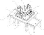
FIG. 1 is a schematic diagram of the overall structure of an embodiment of the present invention;
FIG. 2 is a schematic structural view of a material crushing module according to an embodiment of the present invention;
FIG. 3 is a schematic bottom view of a material crushing module according to an embodiment of the present invention;
FIG. 4 is an enlarged schematic view of FIG. 3 at A;
FIG. 5 is a schematic view of another perspective of a material reduction module according to an embodiment of the present invention;
FIG. 6 is a schematic diagram of a portion of an embodiment of the present invention;
FIG. 7 is a schematic diagram of a portion of an embodiment of the present invention;
fig. 8 is a partial structural schematic diagram of an embodiment of the present invention.
Detailed Description
The technical solutions in the embodiments of the present invention will be clearly and completely described below with reference to the drawings in the embodiments of the present invention, and it is obvious that the described embodiments are only a part of the embodiments of the present invention, and not all of the embodiments. All other embodiments, which can be derived by a person skilled in the art from the embodiments given herein without making any creative effort, shall fall within the protection scope of the present invention.
In the description of the present invention, it is to be understood that the terms "opening," "upper," "lower," "thickness," "top," "middle," "length," "inner," "peripheral," and the like are used in an orientation or positional relationship merely to facilitate description of the invention and to simplify the description, and are not intended to indicate or imply that the referenced components or elements must be in a particular orientation, constructed and operative in a particular orientation, and are not to be construed as limiting the invention.
As shown in fig. 1, the production device of the honey-flour cakes comprises a supporting plate 1, wherein supporting columns 2 distributed in an array mode are fixedly arranged at the lower end of the supporting plate 1, a conveying belt 3 is arranged under the supporting plate 1, and a first motor 31 for driving the conveying belt 3 to convey is arranged at the side end of the conveying belt 3. The fixed spout 4 that is equipped with the symmetry and sets up in the upper end of backup pad 1, be equipped with connecting plate 5 directly over backup pad 1, the fixed raw material crushing module 6 that is equipped with array distribution in the upper end of connecting plate 5, the fixed evaporation storehouse 7 that dissolves that is equipped with in the upper end of backup pad 1, be equipped with fixed plate 8 directly over evaporation storehouse 7, the fixed telescoping cylinder 9 that is equipped with in upper end of fixed plate 8.
As shown in fig. 2, 3, 4 and 5, the raw material crushing module 6 includes a support table 61, the lower end of the support table 61 is fixedly provided with connecting legs 62 distributed in an array, and the lower ends of the connecting legs 62 are fixedly connected with the upper end of the connecting plate 5. The fixed spliced pole 64 that is equipped with of lower extreme of brace table 61, the fixed mounting panel 63 that is equipped with of lower extreme of spliced pole 64, the fixed broken jar 65 that is equipped with in upper end of mounting panel 63, broken jar 65 runs through brace table 61 to with brace table 61 fixed connection.
The upper end of the supporting table 61 is fixedly provided with a first connecting frame 66 and a second connecting frame 67 which are symmetrically arranged, a first screw rod 68 which is rotatably connected is arranged in the first connecting frame 66, a guide rod 69 which is fixedly connected is arranged in the second connecting frame 67, the first screw rod 68 and the guide rod 69 penetrate through the lifting table 610, the first screw rod 68 is in threaded fit with the lifting table 610, and the guide rod 69 is in sliding connection with the lifting table 610. The upper end of the first connecting frame 66 is fixedly provided with a second motor 611, and the output end of the second motor 611 is communicated with the first connecting frame 66 and is fixedly connected with the first screw rod 68.
The upper end of the lifting platform 610 is fixedly provided with a third motor 612, the lower end of the lifting platform 610 is provided with a first gear 617 which is connected in a rotating mode, and the output end of the third motor 612 is communicated with the lifting platform and is fixedly connected with the first gear 617. The inner wall of the lifting platform 610 is provided with a gear ring, the lower end of the lifting platform 610 is provided with an annular guide rail, a second gear 618 in a circumferential array is arranged between the first gear 617 and the gear ring, the rotating shaft of the second gear 618 is arranged in the annular guide rail and is in sliding connection with the annular guide rail, and the second gear 618 is meshed with the first gear 617 and the gear ring. The lower extreme of second gear 618 is fixed and is equipped with first cylinder 619, the fixed first rotatory leaf 620 that is equipped with the array distribution of the side of first cylinder 619.
The lower end of the mounting plate 63 is fixedly provided with a connecting rod 613, the lower end of the connecting rod 613 is fixedly provided with a blanking plate 614, the lower end of the mounting plate 63 is fixedly provided with a discharge pipe 615, the discharge pipe 615 is communicated with the mounting plate 63 and is communicated with the crushing tank 65, the blanking plate 614 is provided with a through groove 616, and the through groove 616 is arranged right below the discharge pipe 615. The upper end of the blanking plate 614 is fixedly provided with guide plates 621 which are symmetrically arranged, a first sealing plate 622 is arranged between the guide plates 621, and the first sealing plate 622 is arranged between the blanking plate 614 and the discharge pipe 615 and is in sliding connection with the blanking plate 614 and the discharge pipe 615.
As shown in fig. 6, a second screw rod 41 is rotatably connected in the chute 4, and the second screw rod 41 is a double-head screw rod. Two ends of each sliding chute 4 are provided with bevel gears 42 which are rotatably connected, the bevel gears 42 on two adjacent sliding chutes 4 are meshed, and the second screw rod 41 is communicated with the sliding chutes 4 and fixedly connected with the bevel gears 42. One end of one of the sliding grooves 4 is fixedly provided with a fourth motor 45, and the output end of the fourth motor 45 is communicated with the sliding groove 4 and is fixedly connected with the second screw rod 41. The sliding blocks 43 in sliding connection are symmetrically arranged in the sliding groove 4, and the second screw rod 41 penetrates through the sliding blocks 43 and is in threaded fit with the sliding blocks 43. The slide block 43 is rotatably connected with one end of a rotating rod 44, and the other end of the rotating rod 44 is rotatably connected with the lower end of the connecting plate 5. The upper end of the connecting plate 5 is fixedly provided with material guiding grooves 51 distributed in an array, and the material guiding grooves 51 are arranged below the blanking plate 614.
As shown in fig. 7 and 8, fastening columns 81 distributed in an array are fixedly arranged at the lower end of the fixing plate 8, and the lower ends of the fastening columns 81 are fixedly connected with the support plate 1. A lifting plate 82 is arranged right below the fixing plate 8, and the fastening column 81 penetrates through the lifting plate 82 and is connected with the lifting plate 82 in a sliding manner. The output end of the telescopic cylinder 9 penetrates through the fixing plate 8 and is fixedly connected with the lifting plate 82. The upper end of the lifting plate 82 is fixedly provided with a water storage tank 83, the side end of the water storage tank 83 is fixedly provided with water outlet pipes 84 distributed in an array manner, the water outlet pipes 84 are provided with valves 85, and the water outlets of the water outlet pipes 84 are opposite to the material guide groove 51.
Dissolving evaporation bin 7 and arranging lifter 82 in under, dissolving evaporation bin 7's one end is fixed and is equipped with fifth motor 71, dissolving evaporation bin 7's inner wall is equipped with the first revolving stage 72 of rotation connection, dissolving evaporation bin 7's one end is rotated and is equipped with the second revolving stage 75 that runs through dissolving evaporation bin 7, fifth motor 71's output intercommunication dissolving evaporation bin 7 to with first revolving stage 72 fixed connection. An evaporation plate 86 is fixedly arranged on the inner wall of the dissolving evaporation bin 7. A second cylinder 73 with a circumferential array is rotatably arranged between the first rotary table 72 and the second rotary table 75, second rotating blades 74 distributed in an array are fixedly arranged at the side end of the second cylinder 73, a sixth motor 76 is fixedly arranged at one end of the second rotary table 75, and the output end of the sixth motor 76 is communicated with the second rotary table 75 and is fixedly connected with the second cylinder 73.
The fixed blown down tank 77 that is equipped with of lower extreme of backup pad 1, blown down tank 77 is arranged in directly over conveyer belt 3. The discharge chute 77 is communicated with the dissolution evaporation bin 7. The fixed connecting block 78 that is equipped with in both ends of blown down tank 77, be equipped with the third cylinder 710 of rotation connection in the blown down tank 77, the fixed third rotating vane 711 that is equipped with the array distribution of side of third cylinder 710, one the fixed seventh motor 79 that is equipped with of one end of connecting block 78, the output intercommunication connecting block 78 and blown down tank 77 of seventh motor 79 to with third cylinder 710 fixed connection. The opening of the discharging chute 77 is provided with a second sealing plate 712 which is connected in a sliding manner.
During the use, pour various raw materialss into crushing jar 65 by the staff earlier, then start third motor 612 control first gear 617 and second gear 618 and rotate to make first cylinder 619 and first rotatory leaf 620 smash the stirring to the raw materials in the crushing jar 65, can control second motor 611 simultaneously according to actual production needs and rotate, and then control the height of elevating platform 610, thereby control broken degree.
After the crushing is completed, the first sealing plate 622 is pulled by a manufacturer, so that the discharge pipe 615 is communicated with the through groove 616, the crushed material falls onto the material guide groove 51 from the crushing tank 65 through the discharge pipe 615, then falls into the dissolution evaporation bin 7 and the discharge groove 77 from the material guide groove 51, and then the valve 85 is opened, so that the water in the water storage tank 83 flows onto the material guide groove 51 from the water outlet pipe 84, and finally flows into the dissolution evaporation bin 7 and the discharge groove 77 from the material guide groove 51. When shifting material and water to dissolving evaporation storehouse 7 and blown down tank 77 in, the output that the generation personnel can start fourth motor 45 or control telescoping cylinder 9 according to actual need is flexible for material and hydroenergy can steadily get into dissolving evaporation storehouse 7 and blown down tank 77 in, the condition that can not appear splashing.
After the transfer of the materials and the water is finished, starting the fifth motor 71, the sixth motor 76 and the seventh motor 79 to uniformly mix the materials and the water, simultaneously switching on the evaporation plate 86, heating and evaporating the mixed solution while stirring, turning off the fifth motor 71, the sixth motor 76 and the seventh motor 79 after the water is completely evaporated, and switching off the power supply of the evaporation plate 86, thereby finishing the primary production of the honey cake. And then, the first motor 31 is started to enable the conveying belt 3 to rotate, and the second sealing plate 712 is pulled by the worker, so that the semi-finished honey powder cake falls onto the conveying belt 3 to be transported away, and the semi-finished honey powder cake can be obtained by pressing the semi-finished honey powder cake subsequently.
In the description herein, references to the description of "one embodiment," "an example," "a specific example," etc., mean that a particular feature, structure, material, or characteristic described in connection with the embodiment or example is included in at least one embodiment or example of the invention. In this specification, the schematic representations of the terms used above do not necessarily refer to the same embodiment or example. Furthermore, the particular features, structures, materials, or characteristics described may be combined in any suitable manner in any one or more embodiments or examples.
The foregoing shows and describes the general principles, essential features, and advantages of the invention. It will be understood by those skilled in the art that the present invention is not limited to the embodiments described above, which are described in the specification and illustrated only to illustrate the principle of the present invention, but that various changes and modifications may be made therein without departing from the spirit and scope of the present invention, which fall within the scope of the invention as claimed.
Claims (4)
1. A production device of honey-flour cakes comprises a supporting plate (1) and is characterized in that supporting columns (2) distributed in an array mode are fixedly arranged at the lower end of the supporting plate (1), a conveying belt (3) is arranged under the supporting plate (1), and a first motor (31) for driving the conveying belt (3) to convey is arranged at the side end of the conveying belt (3);
symmetrically arranged sliding chutes (4) are fixedly arranged at the upper end of the supporting plate (1), a connecting plate (5) is arranged right above the supporting plate (1), raw material crushing modules (6) distributed in an array manner are fixedly arranged at the upper end of the connecting plate (5), a dissolving and evaporating bin (7) is fixedly arranged at the upper end of the supporting plate (1), a fixing plate (8) is arranged right above the dissolving and evaporating bin (7), and a telescopic cylinder (9) is fixedly arranged at the upper end of the fixing plate (8);
the raw material crushing module (6) comprises a supporting table (61), connecting legs (62) distributed in an array mode are fixedly arranged at the lower end of the supporting table (61), the lower ends of the connecting legs (62) are fixedly connected with the upper end of a connecting plate (5), a connecting column (64) is fixedly arranged at the lower end of the supporting table (61), a mounting plate (63) is fixedly arranged at the lower end of the connecting column (64), a crushing tank (65) is fixedly arranged at the upper end of the mounting plate (63), and the crushing tank (65) penetrates through the supporting table (61) and is fixedly connected with the supporting table (61);
the upper end of the supporting table (61) is fixedly provided with a first connecting frame (66) and a second connecting frame (67) which are symmetrically arranged, a first screw rod (68) which is rotatably connected is arranged in the first connecting frame (66), a guide rod (69) which is fixedly connected is arranged in the second connecting frame (67), the first screw rod (68) and the guide rod (69) penetrate through the lifting table (610), the first screw rod (68) is in threaded fit with the lifting table (610), the guide rod (69) is in sliding connection with the lifting table (610), the upper end of the first connecting frame (66) is fixedly provided with a second motor (611), and the output end of the second motor (611) is communicated with the first connecting frame (66) and is fixedly connected with the first screw rod (68);
a third motor (612) is fixedly arranged at the upper end of the lifting platform (610), a first gear (617) in rotary connection is arranged at the lower end of the lifting platform (610), the output end of the third motor (612) is communicated with the lifting platform and is fixedly connected with the first gear (617), a gear ring is arranged on the inner wall of the lifting platform (610), an annular guide rail is arranged at the lower end of the lifting platform (610), second gears (618) in a circumferential array are arranged between the first gear (617) and the gear ring, the rotating shaft of each second gear (618) is arranged in the annular guide rail and is in sliding connection with the annular guide rail, the second gears (618) are meshed with the first gear (617) and the gear ring, a first cylinder (619) is fixedly arranged at the lower end of each second gear (618), and first rotating blades (620) distributed in an array are fixedly arranged at the side ends of the first cylinders (619);
a connecting rod (613) is fixedly arranged at the lower end of the mounting plate (63), a blanking plate (614) is fixedly arranged at the lower end of the connecting rod (613), a discharge pipe (615) is fixedly arranged at the lower end of the mounting plate (63), the discharge pipe (615) is communicated with the mounting plate (63) and is communicated with the crushing tank (65), a through groove (616) is formed in the blanking plate (614), the through groove (616) is arranged right below the discharge pipe (615), guide plates (621) are symmetrically arranged at the upper end of the blanking plate (614), a first sealing plate (622) is arranged between the guide plates (621), and the first sealing plate (622) is arranged between the blanking plate (614) and the discharge pipe (615) and is in sliding connection with the blanking plate (614) and the discharge pipe (615);
a second screw rod (41) which is connected in a rotating mode is arranged in each sliding groove (4), the second screw rods (41) are double-ended screw rods, bevel gears (42) which are connected in a rotating mode are arranged at two ends of each sliding groove (4), the bevel gears (42) on two adjacent sliding grooves (4) are meshed, and the second screw rods (41) are communicated with the sliding grooves (4) and are fixedly connected with the bevel gears (42);
one the fixed fourth motor (45) that is equipped with of one end of spout (4), the output intercommunication spout (4) of fourth motor (45) to with second lead screw (41) fixed connection, spout (4) interior symmetry is equipped with sliding connection's slider (43), second lead screw (41) run through slider (43) to with slider (43) screw-thread fit, slider (43) rotate with the one end of bull stick (44) and are connected, the other end of bull stick (44) rotates with the lower extreme of connecting plate (5) to be connected, the fixed baffle box (51) that are equipped with the array distribution in upper end of connecting plate (5), the below of flitch (614) is arranged in baffle box (51).
2. The honey cake production device according to claim 1, wherein the lower end of the fixing plate (8) is fixedly provided with fastening columns (81) distributed in an array manner, the lower end of the fastening columns (81) is fixedly connected with the support plate (1), a lifting plate (82) is arranged under the fixing plate (8), the fastening columns (81) penetrate through the lifting plate (82) and are slidably connected with the lifting plate (82), the output end of the telescopic cylinder (9) penetrates through the fixing plate (8) and is fixedly connected with the lifting plate (82), the upper end of the lifting plate (82) is fixedly provided with a water storage tank (83), the side end of the water storage tank (83) is fixedly provided with water outlet pipes (84) distributed in an array manner, the water outlet pipes (84) are provided with valves (85), and the water outlets of the water outlet pipes (84) are opposite to the guide grooves (51).
3. The honey cake production device according to claim 2, wherein the dissolving and evaporating bin (7) is arranged right below the lifting plate (82), a fifth motor (71) is fixedly arranged at one end of the dissolving and evaporating bin (7), a first rotary table (72) in rotary connection is arranged on the inner wall of the dissolving and evaporating bin (7), a second rotary table (75) penetrating through the dissolving and evaporating bin (7) is rotatably arranged at one end of the dissolving and evaporating bin (7), the output end of the fifth motor (71) is communicated with the dissolving and evaporating bin (7) and is fixedly connected with the first rotary table (72), and an evaporating plate (86) is fixedly arranged on the inner wall of the dissolving and evaporating bin (7);
the rotary type rotary table is characterized in that a second cylinder (73) with a circumferential array is rotatably arranged between the first rotary table (72) and the second rotary table (75), second rotary blades (74) distributed in an array are fixedly arranged at the side end of the second cylinder (73), a sixth motor (76) is fixedly arranged at one end of the second rotary table (75), and the output end of the sixth motor (76) is communicated with the second rotary table (75) and is fixedly connected with the second cylinder (73).
4. A honey cake production device according to claim 3, characterized in that the lower end of the supporting plate (1) is fixedly provided with a discharging groove (77), the discharge chute (77) is arranged right above the conveyor belt (3), the discharge chute (77) is communicated with the dissolution evaporation bin (7), the two ends of the discharge chute (77) are fixedly provided with connecting blocks (78), a third cylinder (710) which is connected in a rotating way is arranged in the discharge chute (77), third rotating blades (711) distributed in an array are fixedly arranged at the side end of the third cylinder (710), a seventh motor (79) is fixedly arranged at one end of one connecting block (78), the output end of the seventh motor (79) is communicated with the connecting block (78) and the discharge chute (77), and is fixedly connected with a third cylinder (710), and a second sealing plate (712) which is in sliding connection is arranged at the opening of the discharge chute (77).
Priority Applications (1)
| Application Number | Priority Date | Filing Date | Title |
|---|---|---|---|
| CN202110557454.9A CN113304831B (en) | 2021-05-21 | 2021-05-21 | Production device of honey powder cake |
Applications Claiming Priority (1)
| Application Number | Priority Date | Filing Date | Title |
|---|---|---|---|
| CN202110557454.9A CN113304831B (en) | 2021-05-21 | 2021-05-21 | Production device of honey powder cake |
Publications (2)
| Publication Number | Publication Date |
|---|---|
| CN113304831A CN113304831A (en) | 2021-08-27 |
| CN113304831B true CN113304831B (en) | 2022-07-12 |
Family
ID=77374025
Family Applications (1)
| Application Number | Title | Priority Date | Filing Date |
|---|---|---|---|
| CN202110557454.9A Active CN113304831B (en) | 2021-05-21 | 2021-05-21 | Production device of honey powder cake |
Country Status (1)
| Country | Link |
|---|---|
| CN (1) | CN113304831B (en) |
Family Cites Families (12)
| Publication number | Priority date | Publication date | Assignee | Title |
|---|---|---|---|---|
| EP3170541B1 (en) * | 2015-11-18 | 2018-09-26 | Bosal Emission Control Systems NV | Combined evaporator and mixer |
| CN108607432A (en) * | 2018-05-22 | 2018-10-02 | 景晓冬 | A kind of mass preparation facilities for pet cub feeding |
| CN108854626A (en) * | 2018-06-12 | 2018-11-23 | 合肥丰洁生物科技有限公司 | A kind of Cosmetic Manufacture crushing, stirring equipment |
| CN109012847A (en) * | 2018-07-18 | 2018-12-18 | 张琴 | One kind being crushed agitating device for material |
| CN109865473A (en) * | 2019-03-08 | 2019-06-11 | 黄伟玲 | A kind of eye cream system of processing and eye cream processing method |
| CN209810343U (en) * | 2019-04-16 | 2019-12-20 | 山西双林富农林开发有限公司 | Oil tree peony washs drying device |
| CN110116034B (en) * | 2019-05-22 | 2020-12-18 | 绩溪县老胡家生态农业科技有限公司 | Device for regenerating building material by using crop straws |
| CN210845999U (en) * | 2019-07-29 | 2020-06-26 | 马鞍山宝信电子科技有限公司 | High raw material mixing mechanism of security for chemical products |
| CN111905607A (en) * | 2020-08-20 | 2020-11-10 | 陈晓明 | Cosmetics mixing stirring equipment |
| CN112371298A (en) * | 2020-10-15 | 2021-02-19 | 袁继秀 | Ore crushing and screening device |
| CN112264160A (en) * | 2020-10-30 | 2021-01-26 | 宁红 | Medical leafy medicinal material grinding device |
| CN214514520U (en) * | 2020-11-20 | 2021-10-29 | 贵州新天鑫化工有限公司 | Concentrated cauldron convenient to ejection of compact |
-
2021
- 2021-05-21 CN CN202110557454.9A patent/CN113304831B/en active Active
Also Published As
| Publication number | Publication date |
|---|---|
| CN113304831A (en) | 2021-08-27 |
Similar Documents
| Publication | Publication Date | Title |
|---|---|---|
| CN209425826U (en) | Concrete central mix plant | |
| CN212283778U (en) | Compound fertilizer homogenizing machine | |
| CN113304831B (en) | Production device of honey powder cake | |
| CN211189951U (en) | Vertical powder mixing mixer | |
| CN212068452U (en) | Multiple dye homogeneous mixing device for printing and dyeing | |
| CN210814812U (en) | High-speed blendor is used in production of nutrition powder | |
| CN210473748U (en) | Mixing arrangement is used in syrup production | |
| CN116651300A (en) | Preparation device and process of epoxy/BMI composite adhesive silver conductive adhesive | |
| CN215877099U (en) | Chinese herbal medicine mixing arrangement of misce bene | |
| CN216171598U (en) | Planetary mixer that security coefficient is high and have dual stirring function | |
| CN209155692U (en) | A kind of medication chemistry mixing machine | |
| CN213556605U (en) | Automatic control ratio coating mixing apparatus | |
| CN211562788U (en) | Pigment homogenizing device | |
| CN210994018U (en) | Multi-color paint mixing planetary stirrer | |
| CN207628289U (en) | A kind of agitator | |
| CN220326762U (en) | Premixed feed proportioning device | |
| CN208898880U (en) | A kind of blueberry beverage ingredient fermentation emulsifying systems | |
| CN110479176A (en) | Mixing device is used in a kind of production of water-repellent paint | |
| CN216760412U (en) | Raw material mixing device for cable material production | |
| CN205760887U (en) | Star lays many ribbons homogenizer | |
| CN106669480A (en) | Multi-layer feed stirrer | |
| CN214438620U (en) | Cosmetics raw materials agitated vessel | |
| CN213254101U (en) | Rolling type finish paint preparation device | |
| CN110354726A (en) | A kind of multicolor finish mixing planetary mixer | |
| CN214681416U (en) | Compound fertilizer production is with mixing blending device |
Legal Events
| Date | Code | Title | Description |
|---|---|---|---|
| PB01 | Publication | ||
| PB01 | Publication | ||
| SE01 | Entry into force of request for substantive examination | ||
| SE01 | Entry into force of request for substantive examination | ||
| GR01 | Patent grant | ||
| GR01 | Patent grant |