CN113290436A - Automatic grinding equipment for guide vane end face - Google Patents
Automatic grinding equipment for guide vane end face Download PDFInfo
- Publication number
- CN113290436A CN113290436A CN202110644785.6A CN202110644785A CN113290436A CN 113290436 A CN113290436 A CN 113290436A CN 202110644785 A CN202110644785 A CN 202110644785A CN 113290436 A CN113290436 A CN 113290436A
- Authority
- CN
- China
- Prior art keywords
- frame
- rack
- guide vane
- grinding
- fixedly installed
- Prior art date
- Legal status (The legal status is an assumption and is not a legal conclusion. Google has not performed a legal analysis and makes no representation as to the accuracy of the status listed.)
- Pending
Links
- 230000005540 biological transmission Effects 0.000 claims abstract description 21
- 238000012937 correction Methods 0.000 claims description 5
- 238000000034 method Methods 0.000 claims description 4
- 238000009826 distribution Methods 0.000 claims description 3
- 238000004519 manufacturing process Methods 0.000 abstract description 5
- 238000003754 machining Methods 0.000 abstract description 2
- 238000005266 casting Methods 0.000 description 3
- 239000007788 liquid Substances 0.000 description 3
- XLYOFNOQVPJJNP-UHFFFAOYSA-N water Substances O XLYOFNOQVPJJNP-UHFFFAOYSA-N 0.000 description 3
- 230000008602 contraction Effects 0.000 description 2
- 238000009792 diffusion process Methods 0.000 description 2
- 238000012546 transfer Methods 0.000 description 2
- 238000013459 approach Methods 0.000 description 1
- 230000009286 beneficial effect Effects 0.000 description 1
- 230000008859 change Effects 0.000 description 1
- 230000007423 decrease Effects 0.000 description 1
- 230000007547 defect Effects 0.000 description 1
- 230000003028 elevating effect Effects 0.000 description 1
- 238000005242 forging Methods 0.000 description 1
- 239000012535 impurity Substances 0.000 description 1
- 238000009434 installation Methods 0.000 description 1
- 230000007246 mechanism Effects 0.000 description 1
- 238000012986 modification Methods 0.000 description 1
- 230000004048 modification Effects 0.000 description 1
- 230000001915 proofreading effect Effects 0.000 description 1
- 238000007528 sand casting Methods 0.000 description 1
Images


Classifications
-
- B—PERFORMING OPERATIONS; TRANSPORTING
- B24—GRINDING; POLISHING
- B24B—MACHINES, DEVICES, OR PROCESSES FOR GRINDING OR POLISHING; DRESSING OR CONDITIONING OF ABRADING SURFACES; FEEDING OF GRINDING, POLISHING, OR LAPPING AGENTS
- B24B7/00—Machines or devices designed for grinding plane surfaces on work, including polishing plane glass surfaces; Accessories therefor
- B24B7/10—Single-purpose machines or devices
- B24B7/16—Single-purpose machines or devices for grinding end-faces, e.g. of gauges, rollers, nuts, piston rings
-
- B—PERFORMING OPERATIONS; TRANSPORTING
- B24—GRINDING; POLISHING
- B24B—MACHINES, DEVICES, OR PROCESSES FOR GRINDING OR POLISHING; DRESSING OR CONDITIONING OF ABRADING SURFACES; FEEDING OF GRINDING, POLISHING, OR LAPPING AGENTS
- B24B27/00—Other grinding machines or devices
- B24B27/0069—Other grinding machines or devices with means for feeding the work-pieces to the grinding tool, e.g. turntables, transfer means
-
- B—PERFORMING OPERATIONS; TRANSPORTING
- B24—GRINDING; POLISHING
- B24B—MACHINES, DEVICES, OR PROCESSES FOR GRINDING OR POLISHING; DRESSING OR CONDITIONING OF ABRADING SURFACES; FEEDING OF GRINDING, POLISHING, OR LAPPING AGENTS
- B24B41/00—Component parts such as frames, beds, carriages, headstocks
- B24B41/005—Feeding or manipulating devices specially adapted to grinding machines
-
- B—PERFORMING OPERATIONS; TRANSPORTING
- B24—GRINDING; POLISHING
- B24B—MACHINES, DEVICES, OR PROCESSES FOR GRINDING OR POLISHING; DRESSING OR CONDITIONING OF ABRADING SURFACES; FEEDING OF GRINDING, POLISHING, OR LAPPING AGENTS
- B24B41/00—Component parts such as frames, beds, carriages, headstocks
- B24B41/06—Work supports, e.g. adjustable steadies
- B24B41/067—Work supports, e.g. adjustable steadies radially supporting workpieces
-
- B—PERFORMING OPERATIONS; TRANSPORTING
- B24—GRINDING; POLISHING
- B24B—MACHINES, DEVICES, OR PROCESSES FOR GRINDING OR POLISHING; DRESSING OR CONDITIONING OF ABRADING SURFACES; FEEDING OF GRINDING, POLISHING, OR LAPPING AGENTS
- B24B47/00—Drives or gearings; Equipment therefor
- B24B47/22—Equipment for exact control of the position of the grinding tool or work at the start of the grinding operation
Landscapes
- Engineering & Computer Science (AREA)
- Mechanical Engineering (AREA)
- Constituent Portions Of Griding Lathes, Driving, Sensing And Control (AREA)
Abstract
The invention relates to the field of machining, in particular to automatic grinding equipment for guide vane end faces, which comprises: a frame; the transmission device is fixedly arranged above the rack and is arranged along the long edge direction of the rack; the rotary clamping device is fixedly arranged at one end of the transmission device in a vertical state, and the output end of the rotary clamping device faces to the position right above the transmission device; the grinding device is arranged along the long side direction of the rack, the grinding device is erected and mounted at one end of the rack, and the output end of the grinding device faces the end part of the rack; the collecting device is arranged in the middle of the frame and the grinding device and used for storing guide vanes after grinding is completed, the equipment can automatically complete the end face grinding work of the guide vanes, manual work is not needed, operation is simple, and the production work of the guide vanes can be greatly increased.
Description
Technical Field
The invention relates to the field of machining, in particular to automatic grinding equipment for guide vane end faces.
Background
The guide vane is a rotary energy device of the centrifugal pump, and is used for collecting liquid thrown out by the impeller, so that the flow speed of the liquid is reduced, part of speed energy head is converted into pressure energy head, and then the pressure energy head is uniformly introduced into the next stage or is discharged through the diffusion pipe, and the guide vane can be divided into a radial guide vane and a flow channel type guide vane according to the structural form of the guide vane. The forward guide vane and the reverse guide vane of the flow channel type guide vane are cast together, and a continuous flow channel is arranged in the middle, so that liquid flows in the continuous flow channel, dead corners and sudden diffusion are not easy to form, the speed change is uniform, the hydraulic performance is good, but the structure is complex, and the manufacturing manufacturability is poor. The guide vane is one of the most important casting and forging pieces in the water guide mechanism of the water turbine generator set, and the manufacturing of the guide vane is a great problem in manufacturing large-scale water turbine generator sets. The guide vane is produced by sand casting in the past, the internal quality of a casting is unstable, and the common casting defects such as shrinkage porosity, shrinkage cavity, air holes, impurities, cracks and the like are easily generated, so that multiple steps are particularly important in the production process.
Disclosure of Invention
In order to solve the technical problems, the technical scheme adopted by the invention is as follows:
preferably, an automatic grinding device for the end face of the guide vane comprises:
a frame;
the transmission device is fixedly arranged above the rack and is arranged along the long edge direction of the rack;
the rotary clamping device is fixedly arranged at one end of the transmission device in a vertical state, and the output end of the rotary clamping device faces to the position right above the transmission device;
the grinding device is arranged along the long side direction of the rack, the grinding device is erected and mounted at one end of the rack, and the output end of the grinding device faces the end part of the rack;
and the collecting device is arranged in the middle of the rack and the grinding device and is used for storing guide vanes after grinding is finished.
Preferably, the transmission means comprises:
chain slat type conveyer, with frame fixed mounting, chain slat type conveyer fixed mounting in the top of frame, chain slat type conveyer sets up along the long limit direction level of frame, and the top of chain slat type conveyer still is provided with a plurality of correction framves along the long limit direction equidistance distribution of chain slat type conveyer, corrects the frame and is used for proofreading and correct the stator, makes its stator remain state placed in the middle all the time at the in-process of transmission.
Preferably, the rotary clamping device includes:
the first mounting rack is arranged at the side of the rack;
the lifting device is arranged in a vertical state, and the rotating device is fixedly arranged at the top end of the first mounting frame;
the rotating device is arranged at 90 degrees by taking the long side direction of the lifting device as a reference;
and the two clamping devices are respectively and fixedly arranged at the output end of the rotating device.
Preferably, the lifting device includes:
the second mounting frame is fixedly arranged above the first mounting frame;
the sliding sleeve column is arranged in a vertical state, the lower end of the sliding sleeve column is fixedly installed with the second installation frame, a rectangular cavity is further formed in the top end of the sliding sleeve column, and sliding grooves are further formed in two sides of the cavity;
the first electric push rod is arranged in a vertical state and is arranged in a rectangular cavity formed in the top end of the sliding sleeve column;
the sliding column is arranged inside the sliding sleeve column in a sliding mode, the lower end of the sliding column is further provided with a rectangular cavity, the output end of the first electric push rod is abutted to the top end of the cavity, sliding rails are further arranged on two sides of the sliding column and are used for being connected with sliding grooves formed in the sliding sleeve column in a sliding mode.
Preferably, the rotating means comprises:
the third mounting rack is fixedly mounted with the sliding upright post, and the third mounting rack is fixedly mounted beside the top end of the sliding upright post;
the output shaft of the first servo motor penetrates through the third mounting frame, and a first gear is further fixedly mounted at the output end of the first servo motor;
the first rotating shaft is rotatably arranged at the top end of the sliding upright post, the first rotating shaft and the sliding upright post are arranged in a right-angle state, a second gear is fixedly arranged at the end part of the first rotating shaft close to the third mounting frame, and the second gear is in meshed rotary connection with the first gear;
and the rotating frame is fixedly arranged at one end of the first rotating shaft, and the rotating frame is far away from the second gear and is fixedly arranged at the other end of the first rotating shaft.
Preferably, the clamping device comprises:
the pneumatic clamping jaws are fixedly installed with the rotating frame and are provided with a plurality of pneumatic clamping jaws, and the pneumatic clamping jaws are fixedly installed at two ends of the rotating frame respectively;
the clamping blocks are provided with a plurality of clamping blocks, and the clamping blocks are fixedly arranged on each contraction block at the output end of the pneumatic clamping jaw respectively.
Preferably, the grinding device includes:
the first support frame is arranged at one end of the rack in a vertical state;
the first linear driver is fixedly installed on the first support frame, and the first linear driver is fixedly installed above the first linear driver;
the grinding assembly is fixedly installed on the output end of the first linear driver.
Preferably, the first line driver includes:
the screw rod sliding table is arranged above the first support frame and arranged along the long edge direction of the top end of the first support frame.
Preferably, the grinding assembly comprises:
the fourth mounting frame is fixedly mounted with the screw rod sliding table, the fourth mounting frame is fixedly mounted at the output end of the screw rod sliding table, and the top end of the fourth mounting frame is also fixedly provided with a connecting frame;
the second servo motor is fixedly arranged with the connecting frame, the second servo motor is fixedly arranged at one end of the connecting frame, and an output shaft of the second servo motor penetrates through the connecting frame and is arranged towards the direction of the rotary clamping device;
the second pivot, the rotatable setting in the middle part of link of second pivot, the axis of second pivot and the long limit direction of lead screw slip table are parallel state setting, the one end of second pivot and second servo motor's output fixed connection, and the other end of keeping away from second servo motor still fixed mounting has the grinding head.
Preferably, the collecting means comprises:
the collecting box is a rectangular box body and is arranged in the middle of the rack and the grinding device in a vertical state;
the guide groove is fixedly installed on the collecting box, and the guide groove is fixedly installed on the top end of the collecting box.
Compared with the prior art, the invention has the beneficial effects that:
the invention completes the automatic transmission work of the guide vane through the transmission device, and the concrete steps are as follows: the transmission device transmits the guide vane placed above towards the direction of the rotary clamping device in a working state, and stops when the guide vane is transmitted to the position right below the output end of the rotary clamping device;
the invention finishes the clamping and rotating work of the guide vane by rotating the clamping device, and comprises the following specific steps: the rotary clamping device is used for clamping the guide vane transmitted above the transmission device and then driving the guide vane to rotate clockwise by 90 degrees so that the lower part of the guide vane is arranged towards the output end of the grinding device;
the invention finishes the grinding work of the guide vane and the collection work after grinding through the grinding device and the collection device, and comprises the following specific steps: and then, the grinding device is driven to grind the guide vane, the ground guide vane is returned by 45 degrees in a counterclockwise way at the driving guide vane, and then the guide vane clamped by the output end is released to enable the guide vane to freely fall into the collecting device.
Drawings
FIG. 1 is a perspective view of the present invention;
FIG. 2 is a perspective view of the transfer device and rotary clamping device of the present invention;
FIG. 3 is a perspective view of the transfer device of the present invention;
FIG. 4 is a perspective view of the rotary clamping device of the present invention;
FIG. 5 is a perspective view of the rotary device of the present invention;
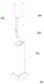
FIG. 6 is a perspective view of the lift device of the present invention;
FIG. 7 is a side view of the lift of the present invention;
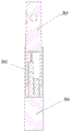
FIG. 8 is a cross-sectional view taken at B-B of FIG. 7;
FIG. 9 is a perspective view of the grinding apparatus of the present invention;
fig. 10 is a perspective view showing a partial structure of the grinding apparatus of the present invention.
The reference numbers in the figures are:
1-a frame;
2-a transmission device; 2 a-a flight conveyor; 2 b-a calibration stand;
3-rotating the clamping device; 3 a-a first mounting frame; 3 b-a lifting device; 3b 1-second mount; 3b 2-sliding sleeve post; 3b 3-first electric putter; 3b 4-sliding posts; 3b 5-slide rail; 3 c-a rotating device; 3c 1-third mount; 3c 2-first servomotor; 3c3 — first gear; 3c4 — second gear; 3c5 — first shaft; 3c 6-turret; 3 d-a clamping device; 3d 1-pneumatic jaws; 3d 2-clamping block; 3d 3-contact block;
4-grinding device; 4 a-a first linear driver; 4a 1-screw rod sliding table; 4 b-a grinding assembly; 4b 1-fourth mount; 4b 2-connecting frame; 4b 3-second servomotor; 4b4 — second shaft; 4b 5-grinding head; 4 c-a first support frame;
5-a collecting device; 5 a-a collection box; 5 b-guide groove.
Detailed Description
The following description is presented to disclose the invention so as to enable any person skilled in the art to practice the invention. The preferred embodiments in the following description are given by way of example only, and other obvious variations will occur to those skilled in the art.
Referring to fig. 1 and 10, an automatic grinding apparatus for an end surface of a guide vane includes:
a frame 1;
the conveying device 2 is fixedly installed with the rack 1, the conveying device 2 is fixedly installed above the rack 1, and the conveying device 2 is arranged along the long edge direction of the rack 1;
the rotary clamping device 3 is fixedly arranged at one end of the conveying device 2 in a vertical state, and the output end of the rotary clamping device 3 faces to the position right above the conveying device 2;
the grinding device 4 is arranged along the long side direction of the frame 1, the grinding device 4 is erected and installed at one end of the frame 1, and the output end of the grinding device 4 is arranged towards the end part of the frame 1;
and the collecting device 5 is arranged in the middle of the frame 1 and the grinding device 4, and the collecting device 5 is used for storing the guide vanes after grinding is finished.
Under the operating condition, the guide vane that transmission device 2 placed the top is transmitted towards rotary clamping device 3 direction, stop when the guide vane transmits to 3 output under rotary clamping device, rotary clamping device 3 works and carries out the centre gripping to the guide vane of transmission device 2 top transmission, then drive the guide vane clockwise rotation 90 degrees and make the below of its guide vane towards the output setting of grinding device 4, then drive grinding device 4 and grind the guide vane, the guide vane after the grinding is at drive guide vane passback 45 degrees, then the guide vane of releasing the output centre gripping makes its guide vane free fall to the inside of collection device 5.
Referring to fig. 3, the transmission device 2 includes:
chain slat type conveyer 2a, with frame 1 fixed mounting, chain slat type conveyer 2a fixed mounting in the top of frame 1, chain slat type conveyer 2a sets up along the long limit direction level of frame 1, and chain slat type conveyer 2 a's top still is provided with a plurality of along the correction frame 2b of chain slat type conveyer 2a long limit direction equidistance distribution, and correction frame 2b is used for proofreaying and correct the stator, makes its stator remain state placed in the middle all the time at the in-process of transmission.
The chain conveyor 2a is used for conveying the guide vanes towards the rotating and clamping device 3.
Referring to fig. 4, the rotary clamping device 3 includes:
the first mounting frame 3a is arranged at the side of the rack 1;
the lifting device 3b is arranged in a vertical state, and the rotating device 3c is fixedly arranged at the top end of the first mounting frame 3 a;
a rotating device 3c, the rotating device 3c is arranged at 90 degrees by taking the long side direction of the lifting device 3b as a reference;
and two clamping devices 3d are arranged, and the clamping devices 3d are respectively and fixedly arranged at the output end of the rotating device 3 c.
When the stator is got rotatoryly when needs are got to the clamp under operating condition, drive rotary device 3c rotates, make its rotary device 3 c's output towards the stator directly over, rotary device 3c is close to towards the stator in vertical decline under elevating gear 3 b's drive, then accomplish the centre gripping to the stator through rotary device 3c tip fixed mounting's 3d, drive rotary device 3c at last and drive clamping device 3d and carry out clockwise 90 degrees rotations, make the bottom of its stator towards the output setting of grinding device 4.
Referring to fig. 6, 7, and 8, the lifting device 3b includes:
the second mounting rack 3b1, the second mounting rack 3b1 is fixedly arranged above the first mounting rack 3 a;
the sliding sleeve column 3b2 and the sliding sleeve column 3b2 are arranged in a vertical state, the lower end of the sliding sleeve column 3b2 is fixedly mounted with the second mounting rack 3b1, a rectangular cavity is further arranged inside the top end of the sliding sleeve column 3b2, and sliding grooves are further formed in two sides of the cavity;
the first electric push rod 3b3 and the first electric push rod 3b3 are arranged in a vertical state, and the first electric push rod 3b3 is arranged in a rectangular cavity formed in the top end of the sliding sleeve column 3b 2;
the sliding upright post 3b4, the sliding upright post 3b4 is slidably arranged in the sliding sleeve post 3b2, the lower end of the sliding upright post 3b4 is further provided with a rectangular cavity, the output end of the first electric push rod 3b3 is abutted to the top end of the cavity, the two sides of the sliding upright post 3b4 are further provided with sliding rails 3b5, and the sliding rails 3b5 are used for being slidably connected with sliding grooves formed in the sliding sleeve post 3b 2.
Under the working state, the first electric push rod 3b3 is driven to work, so that the output end of the first electric push rod 3b3 extends to vertically push the sliding upright post 3b4 upwards from the inside of the sliding upright post 3b4 to lift, the sliding upright post 3b4 is pushed by the first electric push rod 3b3 to be matched with the sliding groove and the sliding rail 3b5, so that the sliding upright post 3b4 can complete vertical lifting and descending work inside the sliding sleeve post 3b2, and the rotating device 3c fixedly mounted at the top end of the sliding upright post 3b4 is driven to perform vertical lifting work.
Referring to fig. 5, the rotating device 3c includes:
the third mounting rack 3c1, the third mounting rack 3c1 and the sliding upright post 3b4 are fixedly mounted, and the third mounting rack 3c1 is fixedly mounted at the side of the top end of the sliding upright post 3b 4;
the first servo motor 3c2, the first servo motor 3c2 and the third mounting rack 3c1 are fixedly mounted, an output shaft of the first servo motor 3c2 penetrates through the third mounting rack 3c1, and a first gear 3c3 is further fixedly mounted at the output end of the first servo motor 3c 2;
the first rotating shaft 3c5, the first rotating shaft 3c5 is rotatably mounted at the top end of the sliding upright post 3b4, the first rotating shaft 3c5 and the sliding upright post 3b4 are arranged in a right-angle state, the end part of the first rotating shaft 3c5 close to the third mounting rack 3c1 is also fixedly mounted with a second gear 3c4, and the second gear 3c4 is meshed with the first gear 3c3 and is in rotating connection;
the rotating frame 3c6, the rotating frame 3c6 are fixedly mounted at one end of the first rotating shaft 3c5, and the rotating frame 3c6 is far away from the second gear 3c4 and fixedly mounted at the other end of the first rotating shaft 3c 5.
Under the working state, an external power supply is connected to drive the first servo motor 3c2 to rotate to drive the first gear 3c3 fixedly installed at the output end to rotate, the first gear 3c3 rotates to drive the second gear 3c4 connected with the first gear in a meshed and rotating mode to rotate, so that the first rotating shaft 3c5 is driven to rotate at the top end of the sliding upright post 3b4, the first rotating shaft 3c5 rotates to drive the rotating frame 3c6 fixedly installed at the rotating end to rotate, and therefore the clamping devices 3d fixedly installed at the two ends of the rotating frame 3c6 are driven to rotate.
Referring to fig. 4, the holding device 3d includes:
the pneumatic clamping jaws 3d1, the pneumatic clamping jaws 3d1 and the rotating frame 3c6 are fixedly installed, the number of the pneumatic clamping jaws 3d1 is multiple, and the pneumatic clamping jaws 3d1 are respectively and fixedly installed at two ends of the rotating frame 3c 6;
the clamping block 3d2, the clamping block 3d2 have a plurality, the clamping block 3d2 is fixedly arranged on each contraction block at the output end of the pneumatic clamping jaw 3d1 respectively.
Drive a plurality of tight piece 3d2 of clamp of output end fixed mounting under pneumatic clamping jaw 3d 1's drive under operating condition and contract to the completion is to the centre gripping work of stator top, press from both sides tight piece 3d2 and be the arc, the arc can be better contradict the chucking with the outer wall of stator, and the middle part of arc still is provided with and supports touch multitouch 3d3, support touch multitouch 3d3 and be used for preventing the stator when grinding device 4 grinds the stator because the thrust of grinding device 4 output leads to the stator to shrink back.
Referring to fig. 9 and 10, the grinding apparatus 4 includes:
the first support frame 4c is arranged at one end of the rack 1 in a vertical state;
the first linear driver 4a is fixedly installed with the first support frame 4c, and the first linear driver 4a is fixedly installed above the first linear driver 4 a;
and the grinding assembly 4b is fixedly arranged with the first linear driver 4a, and the grinding assembly 4b is fixedly arranged at the output end of the first linear driver 4 a.
When the guide vane needs to be ground in the advancing direction, the first linear driver 4a is driven to work to drive the output end fixedly-mounted grinding assembly 4b to move towards the guide vane, and then the output end of the grinding assembly 4b is driven to rotate to grind the guide vane.
Referring to fig. 9, the first line driver 4a includes:
the screw rod sliding table 4a1 and the screw rod sliding table 4a1 are arranged above the first support frame 4c, and the screw rod sliding table 4a1 is arranged along the long side direction of the top end of the first support frame 4 c.
The screw sliding table 4a1 is used for driving the grinding assembly 4b to reciprocate back and forth along the long side direction of the screw sliding table 4a 1.
Referring to fig. 10, the grinding assembly 4b includes:
the fourth mounting frame 4b1, the fourth mounting frame 4b1 and the screw rod sliding table 4a1 are fixedly mounted, the fourth mounting frame 4b1 is fixedly mounted at the output end of the screw rod sliding table 4a1, and the top end of the fourth mounting frame 4b1 is also fixedly mounted with a connecting frame 4b 2;
the second servo motor 4b3, the second servo motor 4b3 and the connecting frame 4b2 are fixedly installed, the second servo motor 4b3 is fixedly installed at one end of the connecting frame 4b2, and the output shaft of the second servo motor 4b3 passes through the connecting frame 4b2 and is arranged towards the direction of the rotary clamping device 3;
the second rotating shaft 4b4 and the second rotating shaft 4b4 are rotatably arranged in the middle of the connecting frame 4b2, the axis of the second rotating shaft 4b4 is parallel to the long side direction of the screw rod sliding table 4a1, one end of the second rotating shaft 4b4 is fixedly connected with the output end of the second servo motor 4b3, and the other end far away from the second servo motor 4b3 is also fixedly provided with a grinding head 4b 5.
When the guide vane needs to be ground in a working state, an external power supply is connected to drive the second servo motor 4b3 to rotate to drive the second rotating shaft 4b4 fixedly mounted at the output end to rotate, the second rotating shaft 4b4 drives the grinding head 4b5 fixedly mounted at the other end to rotate at a high speed, and finally the guide vane is driven by the screw rod sliding table 4a1 to approach the guide vane, so that the grinding work of the guide vane is completed.
Referring to fig. 1, the collecting device 5 includes:
the collecting box 5a is a rectangular box body, and the collecting box 5a is vertically arranged in the middle of the rack 1 and the grinding device 4;
the guide groove 5b, guide groove 5b and collecting box 5a fixed mounting, guide groove 5b fixed mounting is in the top of collecting box 5 a.
The collecting box 5a is used for collecting the guide vane after grinding is finished, the guide groove 5b is used for guiding work, and guide vanes are dredged to enter the collecting box 5a, so that the collection work of the guide vane is completed.
The working principle of the invention is as follows:
the method comprises the following steps: the transmission device 2 transmits the guide vane placed above towards the direction of the rotary clamping device 3 in a working state, and stops when the guide vane is transmitted to the position right below the output end of the rotary clamping device 3;
step two: the rotary clamping device 3 works to clamp the guide vane transmitted above the transmission device 2, and then drives the guide vane to rotate clockwise by 90 degrees so that the lower part of the guide vane faces the output end of the grinding device 4;
step three: then the grinding device 4 is driven to grind the guide vane, the ground guide vane returns 45 degrees in a counterclockwise way at the driving guide vane, and then the guide vane clamped by the output end is released to enable the guide vane to freely fall into the collecting device 5.
The foregoing has described the general principles, principal features, and advantages of the invention. It will be understood by those skilled in the art that the present invention is not limited to the embodiments described above, which are merely illustrative of the principles of the invention, but that various changes and modifications may be made without departing from the spirit and scope of the invention, which fall within the scope of the invention as claimed. The scope of the invention is defined by the appended claims and equivalents thereof.
Claims (10)
1. An automatic grinding equipment of stator terminal surface characterized in that includes:
a frame (1);
the conveying device (2) is fixedly installed with the rack (1), the conveying device (2) is fixedly installed above the rack (1), and the conveying device (2) is arranged along the long side direction of the rack (1);
the rotary clamping device (3) is fixedly arranged at one end of the conveying device (2) in a vertical state, and the output end of the rotary clamping device (3) faces to the position right above the conveying device (2);
the grinding device (4) is arranged along the long side direction of the rack (1), the grinding device (4) is erected and installed at one end of the rack (1), and the output end of the grinding device (4) faces the end of the rack (1);
the collecting device (5) is arranged in the middle of the rack (1) and the grinding device (4), and the collecting device (5) is used for storing guide vanes after grinding is finished.
2. An automatic grinding device of guide vane end faces according to claim 1, characterized in that the conveying device (2) comprises:
chain slat type conveyer (2 a), and frame (1) fixed mounting, chain slat type conveyer (2 a) fixed mounting in the top of frame (1), chain slat type conveyer (2 a) set up along the long edge direction level of frame (1), the top of chain slat type conveyer (2 a) still is provided with a plurality of correction framves (2 b) along chain slat type conveyer (2 a) long edge direction equidistance distribution, correction frame (2 b) are used for correcting the stator, make its stator remain the state of centering all the time at the in-process of transmission.
3. An automatic grinding device of guide vane end faces according to claim 2, characterized in that the rotary clamping device (3) comprises:
the first mounting rack (3 a), the first mounting rack (3 a) is arranged at the side of the rack (1);
the lifting device (3 b) is arranged in a vertical state, and the rotating device (3 c) is fixedly arranged at the top end of the first mounting frame (3 a);
a rotating device (3 c), wherein the rotating device (3 c) is arranged at 90 degrees by taking the long side direction of the lifting device (3 b) as a reference;
and two clamping devices (3 d) are arranged, and the two clamping devices (3 d) are respectively and fixedly arranged at the output end of the rotating device (3 c).
4. An automatic grinding apparatus of guide vane end faces according to claim 3, characterized in that the lifting device (3 b) comprises:
the second mounting rack (3 b 1), the second mounting rack (3 b 1) is fixedly arranged above the first mounting rack (3 a);
the sliding sleeve column (3 b 2), the sliding sleeve column (3 b 2) is arranged in a vertical state, the lower end of the sliding sleeve column (3 b 2) is fixedly installed with the second mounting rack (3 b 1), a rectangular cavity is further arranged inside the top end of the sliding sleeve column (3 b 2), and sliding grooves are further formed in two sides of the cavity;
the first electric push rod (3 b 3), the first electric push rod (3 b 3) is arranged in a vertical state, and the first electric push rod (3 b 3) is arranged in a rectangular cavity formed in the top end of the sliding sleeve column (3 b 2);
slide column (3 b 4), slide column (3 b 4) slidable sets up in the inside of sliding sleeve post (3 b 2), and the rectangle cavity has still been seted up to the lower extreme of slide column (3 b 4), the output of first electric putter (3 b 3) with the inside top of cavity is contradicted, and the both sides of slide column (3 b 4) still are provided with slide rail (3 b 5), slide rail (3 b 5) be used for with the inside spout sliding connection who sets up of sliding sleeve post (3 b 2).
5. An automatic grinding device of guide vane end faces according to claim 4, characterized in that the rotating means (3 c) comprises:
the third mounting rack (3 c 1), the third mounting rack (3 c 1) and the sliding upright post (3 b 4) are fixedly mounted, and the third mounting rack (3 c 1) is fixedly mounted at the side of the top end of the sliding upright post (3 b 4);
the first servo motor (3 c 2), the first servo motor (3 c 2) and the third mounting rack (3 c 1) are fixedly mounted, an output shaft of the first servo motor (3 c 2) penetrates through the third mounting rack (3 c 1) to be arranged, and the output end of the first servo motor (3 c 2) is further fixedly mounted with a first gear (3 c 3);
the first rotating shaft (3 c 5), the first rotating shaft (3 c 5) is rotatably mounted at the top end of the sliding upright post (3 b 4), the first rotating shaft (3 c 5) and the sliding upright post (3 b 4) are arranged in a right-angle state, a second gear (3 c 4) is fixedly mounted at the end part of the first rotating shaft (3 c 5) close to the third mounting rack (3 c 1), and the second gear (3 c 4) is in meshing rotation connection with the first gear (3 c 3);
and the rotating frame (3 c 6), the rotating frame (3 c 6) is fixedly arranged at one end of the first rotating shaft (3 c 5), and the rotating frame (3 c 6) is far away from the second gear (3 c 4) and is fixedly arranged at the other end of the first rotating shaft (3 c 5).
6. An automatic grinding device of guide vane end faces according to claim 5, characterized in that the clamping device (3 d) comprises:
the pneumatic clamping jaws (3 d 1), the pneumatic clamping jaws (3 d 1) and the rotating frame (3 c 6) are fixedly installed, the number of the pneumatic clamping jaws (3 d 1) is multiple, and the pneumatic clamping jaws (3 d 1) are respectively and fixedly installed at two ends of the rotating frame (3 c 6);
the clamping block (3 d 2), the clamping block (3 d 2) has a plurality of, and the clamping block (3 d 2) is respectively fixed and installed on each shrink block of the output end of the pneumatic clamping jaw (3 d 1).
7. An automatic grinding device of guide vane end faces according to claim 1, characterized in that the grinding device (4) comprises:
the first support frame (4 c), the first support frame (4 c) is arranged at one end of the rack (1) in a vertical state;
the first linear driver (4 a), the first linear driver (4 a) and the first support frame (4 c) are fixedly installed, and the first linear driver (4 a) is fixedly installed above the first linear driver (4 a);
the grinding assembly (4 b) is fixedly installed with the first linear driver (4 a), and the grinding assembly (4 b) is fixedly installed at the output end of the first linear driver (4 a).
8. An automatic grinding device of guide vane end faces according to claim 7, characterized in that the first linear drive (4 a) comprises:
the lead screw sliding table (4 a 1), the lead screw sliding table (4 a 1) is arranged above the first support frame (4 c), and the lead screw sliding table (4 a 1) is arranged along the long side direction of the top end of the first support frame (4 c).
9. An automatic grinding device of guide vane end faces according to claim 8, characterized in that the grinding assembly (4 b) comprises:
the fourth mounting frame (4 b 1), the fourth mounting frame (4 b 1) and the screw rod sliding table (4 a 1) are fixedly mounted, the fourth mounting frame (4 b 1) is fixedly mounted at the output end of the screw rod sliding table (4 a 1), and the top end of the fourth mounting frame (4 b 1) is also fixedly mounted with a connecting frame (4 b 2);
the second servo motor (4 b 3), the second servo motor (4 b 3) and the connecting frame (4 b 2) are fixedly installed, the second servo motor (4 b 3) is fixedly installed at one end of the connecting frame (4 b 2), and an output shaft of the second servo motor (4 b 3) penetrates through the connecting frame (4 b 2) and is arranged towards the direction of the rotary clamping device (3);
second pivot (4 b 4), the rotatable setting in the middle part of link (4 b 2) of second pivot (4 b 4), the axis of second pivot (4 b 4) is parallel state with the long limit direction of lead screw slip table (4 a 1) and sets up, the one end of second pivot (4 b 4) and the output fixed connection of second servo motor (4 b 3), the other end of keeping away from second servo motor (4 b 3) still fixed mounting has grinding head (4 b 5).
10. An automatic grinding device of guide vane end faces according to claim 9, characterized in that the collecting device (5) comprises:
the collecting box (5 a) is a rectangular box body, and the collecting box (5 a) is vertically arranged in the middle of the rack (1) and the grinding device (4);
the guide groove (5 b) is fixedly installed with the collecting box (5 a), and the guide groove (5 b) is fixedly installed at the top end of the collecting box (5 a).
Priority Applications (1)
| Application Number | Priority Date | Filing Date | Title |
|---|---|---|---|
| CN202110644785.6A CN113290436A (en) | 2021-06-09 | 2021-06-09 | Automatic grinding equipment for guide vane end face |
Applications Claiming Priority (1)
| Application Number | Priority Date | Filing Date | Title |
|---|---|---|---|
| CN202110644785.6A CN113290436A (en) | 2021-06-09 | 2021-06-09 | Automatic grinding equipment for guide vane end face |
Publications (1)
| Publication Number | Publication Date |
|---|---|
| CN113290436A true CN113290436A (en) | 2021-08-24 |
Family
ID=77327845
Family Applications (1)
| Application Number | Title | Priority Date | Filing Date |
|---|---|---|---|
| CN202110644785.6A Pending CN113290436A (en) | 2021-06-09 | 2021-06-09 | Automatic grinding equipment for guide vane end face |
Country Status (1)
| Country | Link |
|---|---|
| CN (1) | CN113290436A (en) |
Cited By (3)
| Publication number | Priority date | Publication date | Assignee | Title |
|---|---|---|---|---|
| CN114346789A (en) * | 2021-12-27 | 2022-04-15 | 李合江 | Continuous production precision grinder |
| CN114800162A (en) * | 2022-06-29 | 2022-07-29 | 上鼓透平风机启东有限公司 | Cutting and grinding device for fan impeller |
| CN115319612A (en) * | 2022-10-13 | 2022-11-11 | 徐州欧润泵业有限公司 | Water pump impeller equipment of polishing |
Citations (9)
| Publication number | Priority date | Publication date | Assignee | Title |
|---|---|---|---|---|
| JPH11320395A (en) * | 1998-05-18 | 1999-11-24 | Nippei Toyama Corp | Grinding system |
| CN102909623A (en) * | 2012-09-12 | 2013-02-06 | 杭州兴发弹簧有限公司 | Pendulum type end surface grinding machine for spring |
| CN202726919U (en) * | 2012-05-30 | 2013-02-13 | 深圳大宇精雕科技有限公司 | Double-head manipulator |
| CN204893421U (en) * | 2015-08-31 | 2015-12-23 | 重庆理工大学 | A fully automatic grinder that is used for oblique facing (operation) of piston ring |
| CN207480592U (en) * | 2017-11-15 | 2018-06-12 | 天津市博盈科技发展股份有限公司 | Grabbing device and manipulator assembly |
| CN109397076A (en) * | 2018-11-09 | 2019-03-01 | 宁波奉化飞天人精密模具设计有限公司 | A kind of grinding attachment for insulating pot shell |
| CN110977752A (en) * | 2019-12-31 | 2020-04-10 | 朱慧 | Full-automatic grinding equipment for outer ring of integral bearing bush workpiece |
| CN210633344U (en) * | 2019-07-29 | 2020-05-29 | 技善自动化科技(上海)有限公司 | Be used for automatic unloading robot apparatus for producing of going up of lathe |
| CN210939261U (en) * | 2019-10-28 | 2020-07-07 | 吉林省计算中心 | Automatic grabbing device of manipulator shifts and overturns |
-
2021
- 2021-06-09 CN CN202110644785.6A patent/CN113290436A/en active Pending
Patent Citations (9)
| Publication number | Priority date | Publication date | Assignee | Title |
|---|---|---|---|---|
| JPH11320395A (en) * | 1998-05-18 | 1999-11-24 | Nippei Toyama Corp | Grinding system |
| CN202726919U (en) * | 2012-05-30 | 2013-02-13 | 深圳大宇精雕科技有限公司 | Double-head manipulator |
| CN102909623A (en) * | 2012-09-12 | 2013-02-06 | 杭州兴发弹簧有限公司 | Pendulum type end surface grinding machine for spring |
| CN204893421U (en) * | 2015-08-31 | 2015-12-23 | 重庆理工大学 | A fully automatic grinder that is used for oblique facing (operation) of piston ring |
| CN207480592U (en) * | 2017-11-15 | 2018-06-12 | 天津市博盈科技发展股份有限公司 | Grabbing device and manipulator assembly |
| CN109397076A (en) * | 2018-11-09 | 2019-03-01 | 宁波奉化飞天人精密模具设计有限公司 | A kind of grinding attachment for insulating pot shell |
| CN210633344U (en) * | 2019-07-29 | 2020-05-29 | 技善自动化科技(上海)有限公司 | Be used for automatic unloading robot apparatus for producing of going up of lathe |
| CN210939261U (en) * | 2019-10-28 | 2020-07-07 | 吉林省计算中心 | Automatic grabbing device of manipulator shifts and overturns |
| CN110977752A (en) * | 2019-12-31 | 2020-04-10 | 朱慧 | Full-automatic grinding equipment for outer ring of integral bearing bush workpiece |
Cited By (3)
| Publication number | Priority date | Publication date | Assignee | Title |
|---|---|---|---|---|
| CN114346789A (en) * | 2021-12-27 | 2022-04-15 | 李合江 | Continuous production precision grinder |
| CN114800162A (en) * | 2022-06-29 | 2022-07-29 | 上鼓透平风机启东有限公司 | Cutting and grinding device for fan impeller |
| CN115319612A (en) * | 2022-10-13 | 2022-11-11 | 徐州欧润泵业有限公司 | Water pump impeller equipment of polishing |
Similar Documents
| Publication | Publication Date | Title |
|---|---|---|
| CN113290436A (en) | Automatic grinding equipment for guide vane end face | |
| US20160354891A1 (en) | Wheel Deburring Device | |
| CN113118696B (en) | Intelligent welding device and method for pipe fitting end flange | |
| CN211193338U (en) | Precision curved surface abrasive belt grinding machine | |
| CN111496750B (en) | Quick positioning device suitable for processing multiple types of flanges and use method | |
| CN211489928U (en) | Machining equipment for pipe fitting connection movable joint | |
| CN111745409B (en) | Multifunctional processing device for aluminum profile processing | |
| CN113118260A (en) | Multifunctional production machine tool for pipe machining and use method | |
| CN112222537A (en) | Preparation method of key component for hydraulic generator impeller | |
| CN114833001A (en) | Building workpiece spraying equipment with automatic cyclic movement function and compression function | |
| CN113909788A (en) | Clamp device convenient to weld for mechanical assembly | |
| CN111230561B (en) | Processing technology for manufacturing steel pipe by galvanized steel pipe truss | |
| CN216506388U (en) | Limiting device for processing injection mold | |
| CN111590319B (en) | Full-automatic assembling machine for drill shaft of crane drill bit | |
| CN114406561A (en) | Equipment for industrial welding and using method | |
| CN209830448U (en) | Plate cutting device | |
| CN217571147U (en) | Chamfering device of sliding bearing | |
| CN220783296U (en) | Petroleum machinery gear accessory abrasive machining machinery | |
| CN212977400U (en) | Cutting device for hub manufacturing | |
| CN212599084U (en) | Numerical control high-speed drilling machine for double-spindle circular tube drill | |
| CN219309205U (en) | Edge sealing device for aluminum ceiling | |
| CN219212656U (en) | Die cutting and changing device for die automatic calibration | |
| CN220613089U (en) | Surface machining device for KK module | |
| CN112338781B (en) | Polishing device for processing semi-automatic nozzle three-way valve cover and confluence core | |
| CN111806956B (en) | Flange processing equipment with centralized conveying and positioning functions |
Legal Events
| Date | Code | Title | Description |
|---|---|---|---|
| PB01 | Publication | ||
| PB01 | Publication | ||
| SE01 | Entry into force of request for substantive examination | ||
| SE01 | Entry into force of request for substantive examination | ||
| RJ01 | Rejection of invention patent application after publication | ||
| RJ01 | Rejection of invention patent application after publication |
Application publication date: 20210824 |